Exit on LAN of PXI
Hello
I use the following materials:
SMU-1062 q
SMU-8108
OR PXI-5600 (02 card for 40 MHz of bandwidth)
SMU-5641R (two entries are used; one for each NI PXI-5600)
PMA-1115
LabVIEW 2009
I use the mode of the instrument to detect the signal to jump and write in a spreadsheet in real time.
My question is that how can I take out from the SMU-1062 q on LAN so that I can re - generate the detected signal? I enclose my VI. Kindly guide me that how I can get my detected signal output on a PXI LAN?
Thank you and best regards,
Rashid
Looks like you want to use published network variable brightness. You can find this information here http://zone.ni.com/devzone/cda/tut/p/id/4679 , but basically, you need to do a LabVIEW on each computer you want to Exchange data between and linking the shared variable between them. At this point you can transfer data from one machine to the other via the LAN to write to a file and view in the User Interface.
Tags: NI Hardware
Similar Questions
-
My old desktop with windows xp pre-impasse manufacturer has just failed the test of authenticity
My old compaq with windows xp pre-impasse manufacturer office just fail the test of authenticity, and I lose the internet connection (even after rebooting). How can I get this problem?
I checked that my wireless router works fine so that cable exit/ethernet LAN to my office are also working.
Help, please! Is there a toll free number to call? I'm not too tech-savvy. Thank you!
I think that all your problems are caused by infections "hijackware.
If doing the clean install, etc., is outside your comfort zone - and there is no shame in admitting this isn't your cup of tea - take the computer to a local, reputable and independent (no BigBoxStoreUSA or Geek Squad) computer repair shop... If you think that a 8 + year old computer worth the expense that would be.
-
Satellite L655D-s5050: PXE - MOF: exit Intel PXE ROM. No boot device
Hello
I have a laptop Satellite L655D-s5050 running windows.
When I put the power, instead of get a toshiba logo, I get a black screen with the command prompt and a few seconds later the following messages:Intel UNDI, PXE - 2.0 (build 083)
Copyright (C) 1997-2000 Intel CorporationFor Atheros PCIE Ethernet Controller v2.0.1.9 (15/12/09)
Check the connection of the cable!
PXE - MOF: Exit Intel PXE ROM.
No boot device - insert boot disk and press any key.When I insert a bootable Windows 7 DVD, the installation process runs very slowly and never ends...
How can I fixed this problem, if you have an idea, please share it with me.
Thank you
Hello
Message PXE is a typical sign of a malfunction of the HARD drive.
Why? Because the laptop is trying to boot from LAN.
Why LAN?
Because other bootable devices have not been found.I would recommend so check the first page of the BIOS. If the HARD drive is not listed, this means that the HARD drive is faulty and should be replaced.
-
EliteBook 8460p: at the same time LAN & WLAN using problem
Hello
I can't use my elitebook 8460p network (LAN), Wireless Network (WLAN) and local at the same time. Both are well configured. The sequence is that when I connect the official LAN in the laptop cable, existing wireless network automatically becomes invalid. If I unplug the LAN, WIFI will automatically connect to the network. Why this is happening, I don't know. Please, help me.
Info:
* windows 7 Professional 64-bit.
* If I press the key again wlan connection both LAN and WLAN, it does not work and will automatically reconnect if the network cable is unplugged.
I know this isn't OS related issue. I know well on the network configuration. It is the first case and applies only to this model (here 8460p). If there is any related issue of BIOS, please help me. I developed, but not found.
Help me, please.
Hello:
There is a setting in the BIOS called LAN/WLAN switching.
The setting is enabled by default.
If you want to have the wireless and ethernet, working at the same time, go into BIOS, find and disable the LAN/WLAN, commissioning, save the changes and exit the BIOS.
-
Can I connect a PXI-8513/XS to a GM LAN using the pin 3 to GND, pin 9 to 12 VDC and PIN 7 CAN_H to the GM LAN?
Need to connect pin 5 COM to GND? I use an unfinished Conect my interface cable for my camera
Hello
It is not necessary to connect pin 5 because this PIN match a shield in option. Here's the manual CAN where you can check the information (Single Wire CAN)
http://www.NI.com/PDF/manuals/370289j.PDF
According to the baud rate you use, you might have problems if not using a complete cable (low speed may operate, but at higher speeds, you may experience some problems).
I hope it's useful!
Concerning
-
How can I send a trig to my PXI system
I have a 4072 Flexdmm and PXI-2532 switch box and 2640 terminal block. The switch is configured as a 4 * 128 matrix and is connected to an external pacemaker current. The pacemaker requires an input trigger and synchronize precisely the system that I would use a generated trigger the NI PXI system and carefully insert it in the Stimulator. How can I do this?
I tried to use the IO to THE but I can't seem to get no pulse the trigger output.
Hello Sam,.
Regarding working with triggers with a multimeter and a switch, two of these modules use triggers to perform handshaking scan-basically using triggers to synchronize the connecting channels 2532 in the commune for DMM measurement. The procedure is the following:
1. the switch establishes a new connection: ch 1 to COM.
2. the switch installs and sends a trigger "Advanced switch" to a TTL line on fht PXI backplane: PXI_Trig0
3. the DMM watches this TTL and when he sees the trigger, he knows that the connection of the switch is good and he can now take a specified action.
4. the DMM is the action and sends a trigger to "Measure" at the bottom of basket: PXI_Trig1
5. the switch looked at this second line and uses the MC trigger to move to the next item in the scan list.
Some things to note: Switch Executive is not able to scan using triggers.
In addition, these places of relaxation (PXI_Trig0 and PXI_Trig1 in the above example) is configured by the user. Take a look at the example program niSwitch DMM switch Handshaking to see how triggers OR DMM and OR-Switch are configured. It is possible to exit the trigger DMM full measure to the socket at the front of the DMM. The connector to THE is intended to be used when a DMM is to control a switch in a chassis SCXI, as on the SCXI-1130. The SCXI-1357 module can be used with and without cable to THE leave the DMM, control the SCXI chassis, and send the trigger to the SCXI.
I guess the question for you is this trigger exactly do you want to export to your Simulator? I told you earlier about triggers using DMM and switch. However, if you want to use some kind of initial startup trigger to synchronize things, you might be out of luck. The DMM and the switch have no way to generate such a release, and even if they did, does not have one of these to access the trigonometric lines of PXI chassis. You would need another module in the chassis that you could take advantage of, for example a PXI-6651 allowing access to the trigonometric lines, if you use the advanced trigger or a switch card DAQ with a counter to generate a pulse that you can use as a trigger.
Kind regards
Frederic M.
-
Hello
I want to use PXI-5105 on SMU 1071 chassis for strain measurment by conneting the strain gauge by the to 5105 wheatstone bridge circuit using BNC cables. I'm using Labview for the same thing.
(i) I get the variable noise (0,008 to 0.010 V) with no connection to the input channel.
(ii) I'm unable to balance / minimise the noise to zero by subtracting signal from one channel to another (differential input).
Data acquisition parameters:
Input voltage: 5V by DC power supply
All cables used are sheathed in copper cables
Sampling rate: 5ms / s
Number of samples to read: 2000
We worked on the reduction of noise for a long time. Any help will be much appreciated.
Thank you
Vinod
Hi Vinod,
Keep in mind the accuracy of the unit 5105 is specified to +/-2mV.
Also, you can check that your device has been calibrated on the outside and in his external calibration cycle.
When I watched a 5105 digital signal in a similar setup to yours, I saw the same kind of (about) + / 2mV noise. I don't think this is unexpected. Especially if you let the front end of your digitizer not completed, it could recover the additional ambient noise.
Why you choose to use this scanner for a measurement of the strain gauge? There are several other products OR Lane County and specifically designed for measures of constraint. Here are a few resources:
Strain with gauges
http://zone.NI.com/DevZone/CDA/tut/p/ID/3642
SMU-43xx Bridge Module Product Pages
http://sine.NI.com/NIPs/CDs/view/p/lang/en/NID/208288
Dynamic signal acquisition board
http://forums.NI.com/T5/dynamic-signal-acquisition/BD-p/100
-Andrew
-
replacing existing ATE traditional PXI based ATE
Hi all
We use a traditional ATE equipped with traditional instruments for example transmissions
 cope, Agilent: switches; Mux; Matrix; DMM; Generating function, Chroma
 ower supply, etc...
I contacted OR to obtain praposal to replace these instruments OR instruments. The price of the products OR is higher than the traditional instruments of compratively. Now it's hard for me to propose this to my managemnt.
Which in general; You people do to replace the traditional ATE with this new S/o, PXI?
Can I use same digitizer for high channel count to replace measuremnt instrument such as scope, DMM?
- DMM: PXI-4072 (I LOVE this DMM)
- Switches/MUX: NOR has a good range of PXI switches that work well. I wanted to play with of Pickering PXI switches, especially their BRIC.
- Function generator: the PXI-5421 is a very good generator of arbitrary signals.
- Power supplies: Agilent has a good series of modular power supplies (N6700 series). You can put up to 4 power supply is a single 1U chassis and communicate with them via LAN.
- I use Chroma electronic loads, but I don't really like them for situations that I was forced to use them. They are really good for loads of constant currents, but I hate them for the constant resistance loads, unless you are less than 100 Ohms. Always looking for alternatives. Also glued using GPIB or serial communication. I'm trying to push to the local network for cost reasons.
- Oscilloscope: I found that the transmissions expanded are the best way to go. It is really hard to replace a real screen on a scope that you can play with during troubleshooting. And the means of integrated measures, I don't have to deal with the wave form myself. Yet once, talk to her on local network.
- Counter source (power supply with a multimeter accurate built in): been using the Keithley 2425. Tempted to look at the NOR meters source especially because Keithley seems just refuse to go to the local network. But it's a counter very good source.
In my honest opinion, PXI has its place and have their own traditional instruments. PXI is very good for the right instruments (switches, multiplexers, DMM, AWG, low current power supplies to). But I find the traditional instruments are necessary for feeds that need to come out of the current charges and decent electronic (again, due to current needs). I used scanning cards of EITHER before, but I always come back when I have to debug and how it is nice to have a real screen showing my waveforms and then be able to play with the sliders on the fly.
-
Pxi different 2-5421 or-tclk synchronization help and reversing a signal
I have 2 PXI-5421 function generators. Screened through my vi I load a .hws file and output the same signal makers 2 all in phase and triggering the same point. I need basically to do, it is reverse one signal of 180 degrees and keep them always trigger the same starting point.
im not sure how is invert the signal on a 5421 or how to separate code so that each signal generator is separated.
Hi Liam,
I did a quick search on your issue and I think it is interesting to try to 'configure exit Mode.vi niFgen' (red border on the screenshot) and the value
output mode of entry to the "arbitrary signals" (right click on the parameter "Output Mode"-> create constant-> select 'arbitrary signals' in the drop-down list).
You could include a code of the error you found in your next reply. Thank you!
All the best,
-
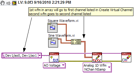
Using Labview and PXI-4461, how can I AO0 output Signal Square and AO1 output waveform
I am using PXI-4461 and Labview, boredom, generating 2 signals simultaneously.
How can I get AO0 out square and exit AO1 SignWave?
Help, please. (The example Code would be nice)
Thank you.
Create two signals and make a table with them. Use DAQmx Create Virtual Channel to create two channels. First waveform will be sent to the first string, second waveform on the second channel.
I understand not all as calendar, clock frequency, amplitude, trigger and other parameters. You can add these things. This is just a basic example.
-
Hello
I try to communicate with the PXI-4072 using VISA drivers. I m using Fluke MetCal / MetTrack to calibrate the 4072 and want to
do this automatically, without use of th niDMM FrontPanel.
But MetTrack Fluke will scan only the RS232, LAN, GPIB and USB Bus for a device, not the PXI chassis.
Anyone know a solution to calibrate or adjust the PXI - 4072 FlexDMM (or any device PXI)?
Thank you
Robert
You must use the API OR-DMM to calibrate the 4072. The generic driver of VISA will not cut, because you will not be able to log of calibration, take action, make adjustments, or really do much else than reading/writing specific registers, which is not supported or recommended. In addition, you cannot use the Soft Front Panel for calibration, as this must be done in a very specific order at a meeting of calibration.
I do not personally know with MetCal/MetTrack, but it seems that Fluke has provided certain procedures for the PXI-4065 and USB-4065. Since they don't seem to have a procedure published for the PXI-4072, if you want to use MetCal, you will need to code your own version of NOR published the calibration process, which is installed with NOR-DMM and is also available via this link (I searched ni.com for "4072 calibration").
In general, for any device PXI, you don't want to use VISA to communicate, but rather use the appropriate API, calling in DLLs of the API (nidmm_32.dll or nidmm_64.dll in the case of NOR-DMM).
Your other alternative is to use NI Calibration Executive, who has the procedure of calibration for all the NOR-DMM ready to go.
Please let us know if we can be of further assistance.
Tobias
Software engineer
Modular instruments
National Instruments
-
I need help to change a VI of the NI PXI-1042 q to USB-6210
Hi all. This is my first post, and I apologize in advance if it is in the wrong place or is not suitable... I was instructed to come here to help.
I'm working on the evolution of a VI that works perfectly with an NI PXI-1042 q on a much smaller unit, the USB-6210. Supposedly the USB-6210 can handle input/output same I need (a read analog at 30 kHz, 2 outputs digital input, written at 10 kHz), however I am having a little trouble to make it work properly. The exits seem to go where they are supposed to, but the new system is orders of magnitude slower than the original, and for the system, I use this is unacceptable.
I'm sure I'm doing something wrong, but I'm about as new to the LabView you can get, so I have no idea where to start. Any help would be appreciated.
More info you might need:
LabVIEW 2010
The VI is attached.
Respectfully,.
Emrys Maier
University of Texas at Arlington Research Institute
Research Assistant
The device is unable to produce the frequency required by the output digital, but the outings of the counter do it perfectly.
Emrys-
-
I have a failure on Port 6 of my caused PXI-6515, I believe, by pins 49 & 50 on my SBC-100 cable being offline. They made so not with the PXI card themselves short-circuit correctly and the connection with one of the pins on the PXI card. From my tests to the MAX the other ports of exit, (4, 5 & 7), agree but port 6 now looks like it is floating and does not not as output. Anyone know if we can fix the card? Or is the card off right now? There seems to be two fuses who agree.
From the material point of view can someone explain what happened.
Any comment is appreciated.
Steve
Hi Steve,.
It seems that a fault has been committed. If you are going to call to try and have the details of the card (or preferably the card itself) at hand because we will ask for certain details, including:
Part number (usually 7 alphanumeric values followed by a dash and 2 digits, for example 186343C-01)
Serial number (usually of 6 alphanumeric values, for example CEDB0C)
and
Details of the computer (the device can be seen in the Manager devices of measurement and Automation Explorer and Windows?)
If you can get your hands on an another PXI-6515 to try the same tests that will still provide proof of fault.
Best regards
Paul
-
IVI Configuration with the PXI-4110 in TestStand
Hi all
Implementation:
PXI-1033 connected through MXI to a PC running Windows 7. LabVIEW 2014. TestStand 2014 (32 bit). DMM PXI-4110 food and PXI-4070.
In MAX, I can open two soft signs and two control units and they work great. In LabVIEW, I can control the two cards as well.
MAX I put in place a pilot and a logical name for my DMM. This unit works very well within TestStand using one-step IVI DMM.
I then configure the 4110 to the MAX with a pilot of the IVI and logical name. Here are my settings:
Name: ni4410_PS
Material: Immobilization of additional hardware and select the PS. This is checked, any other assets are checked.
Software module: NOR-DCPower, 4110 is listed as a device supported.
Virtual names: It is where I am confused, under the name of physics there are four options that arise (0, 1, 2 and 3). This power has only 3 exits, so I'm not sure why four rise. I've done 4 virtual names, one for each of the options. I named the ch0, ch1, ch2 and ch3 respectively.
When I put a power of IVI step TestStand, everything seems to work. I open the configuration window and set my values for each channel. If I try to validate the configuration by deselecting simulate and click init I do not receive an error. As soon as I click on 'Set up' or 'Show Soft Front Panel', I get the following error:
"IVI operation failed set to the name of lgical"OR PS 1'. Details: Possibility of Extention not taken care of by instrument driver. (Base) (- 30717) »
Any information would be appreciated. I tried to play with it for a few hours yesterday and a few colleagues trying to help. We are all under the assumption that it should work.
Thank you!!
Jesse
Hi jesserzamora,
Did you see this link: http://digital.ni.com/public.nsf/allkb/331F2717DBCD1F858625758200745773?OpenDocument
It addresses a failure similar to the step of IVI Power Supply of TestStand.
-
Installtion of Labview RT on the PXI controller
We have a 8106 controller PXI that runs on the Windows operating system. We want to make it work on real-time OS of NOR. What are the steps I need to do to install this. Vascular when I boot in the BIOS of fron LabView RT, it displays "control transfer to the user program. System not configured, restart... ». I am able to connect it to MAX by the host PC and able to install Veristand 2011. But it does not reflect while the boot controller.
Converting Windows a RT, there are some very important things that you must do to handle the conversion. big is your hard drive. Your hard drive needs to be formatted with a FAT32 partition - probably formatted Windows NTFS, RT cannot read or use. Convert your drive will be a manual step for you; If you follow these steps, you can use a disk RT PC Desktop Utility to perform the Exchange against (these instructions with a PXI-8106 module):
First of all, must be a FAT32 partition on it and the format.
- Acquire a drive Flash USB 256 MB or more. Plug it into your host computer.
- Image/Format the USB Flash drive via MAX
- Under tools of-> creating USB utility MAX desktop PC
- Plug the USB key into 8106
- Enter the BIOS of 8106 using the "Delete" key
- Go to the menu "LabVIEW RT" and "Priming" the value "" Windows / other OS '. "
- Press F10 to save and exit, restart the controller.
- Enter the BIOS of 8106 using the "DELETE" key (we had to put the controller for Windows / Other and restart the computer to enable USB be detected/used)
- In the 'Boot' menu, make sure that "USB HDD" (probably also has your mfg of the inserted USB) option is #1 in the startup list (using keys + /)
- In 'Advanced-> Integrated Peripherals' ensure 'Legacy USB Support' is [ENABLED].
- Press F10 to save and exit, restart the controller.
- The startup controller using the USB flash drive.
- In the USB Flash Drive Options, choose the 6 'Options of Format' option (according to the image of the flash player, can say another thing, but option # is the same).
- Choose to format the drive, use the Option #2 in the format "Erase all Partitions on the disk and create a new single Partition" - This clears the disk partition information and creates a single FAT32 partition on the drive.
- FAT32 format (DO NOT use the use of a 8106 - BIOS does not include the system of dependency files).
- Once completed, restart the controller (to do this, you can use Option 9).
Now, we must get the controller to think that it is a PXI and not a desktop RT PC controller
- Enter the BIOS of 8106 using the "Delete" key
- Go into the menu "LabVIEW RT" and "Boot" "LabVIEW RT safe mode" value
- Press F10 to save and exit, restart the controller.
- In MAX, find the device to remote systems. Right click on the device and choose "format disk".
- Once you format the disk, the controller will think it is a PXI controller.
- (You may need to remove the MAX controller and press F5 to detect again for updated images)
Now we are going to put the controller in RT mode so we can use it.
- Enter the BIOS of 8106 using the "Delete" key
- Go to the menu 'LabVIEW RT' and 'Start Configuration' value 'LabVIEW RT'
- Press F10 to save and exit, restart the controller.
There you go. Now you are ready to rule the world in a deterministic way.
-Danny

Maybe you are looking for
-
Links in my gmail does not work, but they work with the chrome browser.
All of a sudden a few days before, the links in my gmail wouldn't work - a new tab comes with gibberish-gook, but I am not taken to any site. When I read my mail using the Chrome browser I have no problem. But I prefer to use Firefox. When I click in
-
The BIOS update does not work on the Satellite - cannot load PHLASHNT.sys
"Cannot load the PHLASHNT.sys driver.It gives then a few silly respons to check if you have admin rights or not.Under windows, very nice everyone has admin right here, that the problem with this :-/
-
HP laptop - 15-ay089tu: compatibility of the BONES of Kali in my HP laptop - 15-ay089tu
Should I extra somethingg to run Kali OS (OS unique) in my HP laptop - 15-ay089tu. I would like to learn more about the compatibility of kerner drivers with hardware.
-
Messages: 4 Registration date: 19/07/2009 0 HP compaq presario F 739AU Internet connectivity problem 2010-01-13 09:53 I reinstalled windows XP Professional on my pc and since this time found that I am not able to connect to the network. I installed
-
I am looking for a restore disc for my pe1050 laptop asus. Did someone help?