faster waveform table is...
Hello, wolrd, another problem im stuck with this is: now that I managed, with the help of good people here, to pass successfully a desired of a servovalve voltage value, I need to arrange an entry which, in my case, two pressure sensors: one of them is implemented before the valve, another is after, so I plugged the two input channels , ai0 ai1 and and created two graphic signals to see the voltage on the sensors. the problem occurred is ridiculous: I have three loops: output (voltage servovalve) and two loops of entry for both sensors, where I added two charts, but when I run the program, one of the charts never work entry, so I decided to do the following: I changed the two graphs to display data from a channel, for example ai0 and its quite logical that it should have the same waveforms , haha not at all, on of them is always frozen. which of them? randomly. and I thought to a next thing: he really resembles the fastest access to the works of waveform graph, one loses the race and is frozen. What could be wrong? I did some tests, and it happens that a problem is not with the connection, nor with sensors. any ideas on that? Thank you
p.s. the vi attached
If the types are the same, simply "dev1\ai0:1". Otherwise, two functions DAQmx create channels wired in sequence.
Tags: NI Hardware
Similar Questions
-
How can I set the time axis on my waveform table to show run time that is to say whenever I start the program I should have 0 as the starting point. I've been messing around with the without success. I'm under Labview 2012.
Thank you!
Townes wrote:
I can't understand what you mean. I have no formal training with labview. It took me a long time to write the simple program that I joined. Any guidance would be greatly appreciated!
Its pretty normal for a beginner to take the time to write code. Right-click the map of waveform > Create > property node > historical data, you will get a property node, keep this at the beginning of the code and create a constant. You can also go to the VI properties and > run and select "clear indicators when it is called.
I recommend you to go through the basic materials of LabVIEW which will give you an understanding on the basics of bases/components of LabVIEW.
-
Control the properties of the graph of a waveform for waveform table.
I'm to customize a waveform graph. I will have no problem using nodes property to define all the things I need to (color plot, the names of axes, etc...). My wave form is actually an array that contains the seven waveforms. The problem is that the property of the waveform graph node changes only trace, legend, etc. the first signal in the graph. They all have the chart perfectly together. However, my application requires the user to be able to select say signals 2, 5 and 7 of the table. When it does, it receives signals of 2, 5 and 7 on the chart, but the legend Watch reports 1, 2 and 3 and they draw in the colours of the signals 1, 2 and 3. Any suggestions on the update of the properties of several plots of a waveform graph?
Also when I want 1 signal trace a curve of waveform. When I want the signals from 2 to 7, I have to draw a second copy of the curve of waveform. For some reason any a waveform table chart cannot double as a unique waveform graph. Any ideas on that? Thanks in advance for your help.
To change the properties of other signals in the chart, you will need to set the ActivePlot property node before writing the color, the name of legend, etc... To display only the selected signals, you could do a couple different things.
(1) set the color of the signals that are not visible by transparency
(2) write NaN values to the curve of waveform of the signal that you do not want to display
-
Hello
First of all, I use LV7.0. I pass data to a waveform chart. A two-dimensional painting converted to a cluster, and then passed to the table data. Graph properties are set to only show that a single conspiracy, but there is so many places on the map I can't make heads or tails of it. See attachment. Thanks for any help, as someone of you could provide.
What is the size of your cluster? That determines how many different parcels you have.
-
Hi, I work with a USB 9162 NI and the NI 9234 4 channels daq, in LabVIEW 8.5. I am acquiring data from a device that produces a ~ square wave and I'm trying to determine and record the frequency of the square wave. The problem that I am currently is that the graphic waveform and table that are produced by the vi correspond. I recently hooked up to a generator of signals set at 500 Hz to a channel and checked against an oscilloscope. I get 500 Hz on waveform graph, but 605 of the table. The graph is truncated to 825 Hz in the x-axis and the 500/605 is ~ 0,825, the same proportion as the truncation/1000 Hz. I have attached the screenshots of the block diagram and front page. Any help to understand why this happens, and fixing it would be greatly appreciated...
Chuck Griesel
All, I got some very good information of Carmen Zheng concern why I saw a mismatch of the screen and writing table. This message was received after several posts back. I have attached the vi containing the solution, as described below.
Thanks a lot for your help!
_ the message _beginning
Hello Chuck,
Please send me this file. I've seen what happens.
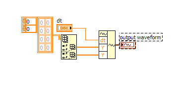
The dynamic data signal that you have acquired by the simulated signal or your hardware contains three components: Y, dt, t0. These components are required to create a waveform correctly. The
component is returned as an array of the values of the waveform and dt data returns the interval in seconds between data points in the waveform. The dt is Fs / #s, this dt value will be
indicate the waveform how to distribute the values Y on the x-axis.The reason of why you saw the incompatibility is that you check out only the component Y, which does not contain information on how to distribute it on the x-axis. The index of this item
does not reflect the position where the value must be shown.The workaround easier that I could find was to create an array with a size of #s, then insert the values in the table are component to the new array, but the index is climbed by the factor of dt.
Please take a look at the attached code.
Let me know if you need more assistance.
Kind regards
Carmen Chan Zheng
Technical sales engineer
National Instrumentsmessage___ ___end
-
How to convert Brown waveform table Orange table
Hey,.
I'm trying my table in a box formla so I want the individual values in this table, but I never came across the Brown son of waveform
I have attached a file paint below, I hope that aid to explain what I mean
I want to go find the frequency & phase of my wave is it able to use thoes values in a calculation
Thanks, I hope this makes sense.
Resolved, regret that turns brown dotted line is a cluster not a waveform.
-
Hello
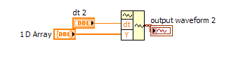
I'm working on a real-time application that adds a new table 1 d to all 2mS, which gives the 2D resulting. How can I convert this waveform 2D arry in a possible minimum period that the application has need of data online.
Thank you
Here is a way. You must add the sampling frequency of youer dt control and you may have transposed the data depending on how it is implemented. The other way would be to convert the 1 d arry waveform before Sane in a 2D array. Make rather a 2D waveform.
-
Waveform table, draw and dynamics of double data
Hi all!
I would get separate plots on a single waveform chart.
In fact, I'm simulating 4 signals (but in reality, it would be the signal from sensors) and I would get 4 plots.
In the end, I only get 3 plots and no 4.
It's very strange... Yet, I chose 'Stack slots' and ' 4 plots illustrated.
In fact, I see that the last data has been merged with the first.
How can I fix it?
Thank you!
I don't know how you got in this State but try to go into the properties of the graph (diagram of front right click and click Properties in the menu) and on the appearance tab, uncheck "stack slots", uncheck "Show Displays digital (s), press the"OK"button, then go to the properties again and select again these two boxes and press OK.» It should correct the problem.
-
How to set the waveform table to start data since the beginning of the race
Create a property of the graph node. The property you are looking for is history. This property, you can clear the table.
-
Hello
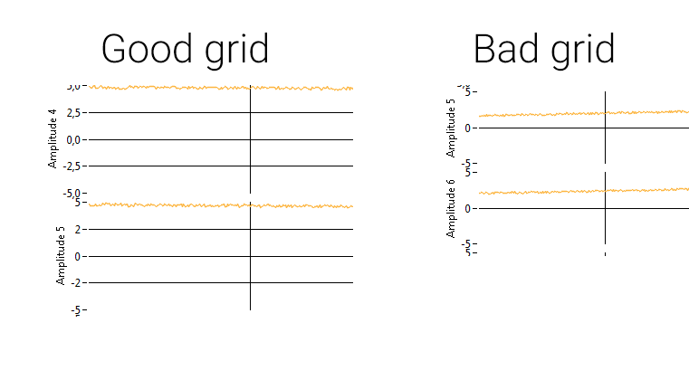
I have a question on the maps of waveform: I made a stacked graph of waveform and I have a weird problem with grids: I each scale ranging from + 5 to-5 and a major increase in 2.5 via a property node (and the minor grid turned transparent). However if it becomes narrowed beyond a certain height, I lose every second increment and the line of the grid, even if I do not change the increment value. It seems that there is a minimal amount of pixel to one grid increment. What is this value? Will there be a chance to continue to move forward on my beginning of mesh? (Because I think that there is still enough room for each major gridlines)
I understand both cultures of images to illustrate my exported graphic problem:
JLP,
By using LabVIEW 2014 I could see the same behavior that you were. It seems that LabVIEW won't ticks if he thinks they are overlapping.
I wasn't able to find the documentation said that directly, but the property to [MarkerValues] node says it will ignore the array if it cannot get values without overlap. You see the same behavior if you increase the size of the text of the increment markers.
To me, it seems that the minimum spacing is set to the size of the text, because if you increase the text size large enough it get rid of line markers, even if your chosen style does not display values (so of course there is no overlap in the text).
-
Waveform table do not see the time correctly
Hello
I am trying to represent the time vs. keithley multimeter voltage using a waveform chart. The voltage is recorded properly, however, the time does not seem to match. It shows approximately 10 times higher seconds. See the attached VI where I also used alternatively a XY Chart. I would like the time to be displayed in the waveform graph as in this chart XY.
In addition, in the XY graph, I had to put up one zero time to obtain the relative time. Is there a simpler way to do rather than use this trick?
Thank you.
-
Only first waveform table has run menu
Hello again all you lovers forum useful!
My multi-graphique card waveform works decently well, but now, for some reason, that only the first parcel in the chart legend displays a customization at runtime the menu when I click on it while the VI runs (allowing me to select the color of the plot, etc.). All the other plots do nothing when I click on them. I don't have any mouse events down or filter of any kind in my VI. Programmatically, I put the number of plots and the size of the legend of the plot, as well as the name of each parcel, including index and color. Any ideas on what could happen?
Thanks a lot as always!
-Joe
-
Hello!
Just a simple question: I have a txt file with the following structure:
2012.03.13 19:13 6.93E - 05
2012.03.13 19:14 6.29E - 05
2012.03.13 19:15 5.66E - 05
2012.03.13 19:16 5.21E - 05. ..
Then delimited by tabs of the values and timestamps.
I want to send them to a waveform graph. Can someone show me "elegant" way to do this, I think I could do it in a very ugly way...?
Samples of data attached and my VI that I wrote so far...
Thanks in advance,
You were very close. I have attached your VI with the analysis of the timestamp. You can find the timestamp format codes in aid of LabVIEW in the Codes of the time Format String Format.
Note that I used only the first two timestamps, assuming that the data has been evenly spaced. You could also use an XY graph and use all the timestamps, if you want. In addition, to get the timestamps to appear on the graph, you must right-click on the chart and clear the option ignore timestamp.
-
How to make the waveform table rows less laeti WITHOUT using a lot of mathematics of interpolation
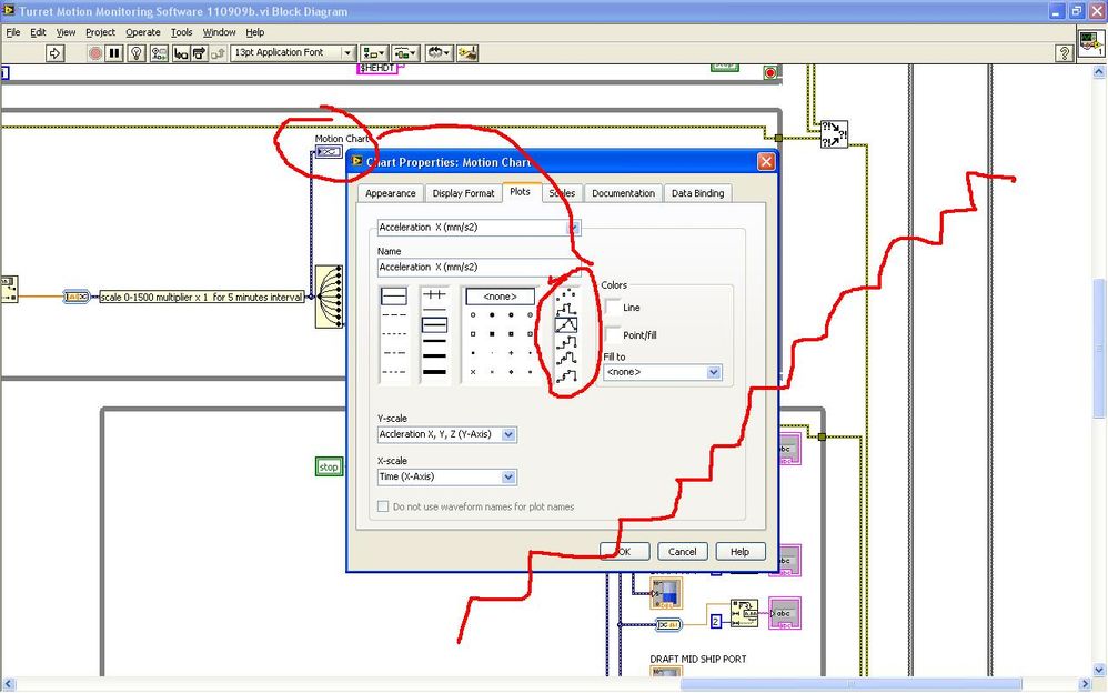
So I use a graph shaped wave, the numbers of entries sequence like that, sensor 22,23,24,25... the graph seems laeti. (Fussy) client says hey I want a good graph, you have function spline or something?
So I was to research the properties of chart and saw the settings below that does not help much. I proposed to the customer (picky) that Hey maybe we can make the balance Y greater for the lines of the stairs will be not so obvious, the customer (picky) says no. So I was sweating on tedious mathematics required for interpolation in the hot oil and noisy, without internet, fortunately the dinner bell rang.

Now is there some function blocks which makes the table lines smooter, a function spline or something? Thank you.
-
Channel separation order waveform table parametricaly?
Hello.
I have an application where I gain two temperature & strain. The number of each type of sensors varies from one test to the other. I want graphic of each type on different graphics so that I can scale properly. I enclose a picture of my application.
Is it possible to control through front?
Say, using a digital command to set the number of strain gauges (first N channels are strain gauges, thermocouples of rest), then separate the data.
Thank you
Usuario
Hi user,
You can use the function split array.
Mike
Maybe you are looking for
-
They both show each other names and the connection of numbers that are the same, but they will not pair with each other. Just bought the other half slate and hoped to have it set up before she drew. The slate will come back?They are certainly compati
-
Why the rejection of multiple photos doesn't work anymore when you change pictures?
Why the rejection of multiple photos doesn't work anymore when you change pictures? Does anyone else have this problem? It works on my other Mac but just stop working on my computer laptop pro, I have the latest OS and it worked until a few weeks ago
-
Need to reformat Vista but don't have the disc
I have windows vista Home premium 64-bit and I need to format, but I don't have the cd I don't have product key what can I please?
-
PowerEdgeT320, UEFI and Windows USB drive > 3 GB
PowerEdge T320 running Windows 2008 R2. If I plug in a USB/3 GB key and restart the server, the "starting Windows" appears for a moment and then it stops with an error. Did not a screenshot, but it's something like "UEFI environment of pre-seed error
-
in windows vista, how to restore the icon of disk deleted on desktop and start menu cleanup and files in 'all courses Accessories folder '.