FFT problem
I'm figuring the FFT of several signals, I have used sine waves in the attached vi to highlight my problem.
I created 3 sinusoidal signals using signal generated express vi.
Sinusoidal signal 1: Fs = 20 Hz
Sine wave 2: Fs = 250 Hz
Sine wave 3: Fs = 500 Hz
I combined these signals in a table and fed in FFT Soectrum (Mag Phase) VI and see the results on a graph in the form of wave. I changed the property of multiplier of charts to the sampling frequency of the singal handset (1 sine wave Sine Wave 2 + Sine Wave 3) which is equal to 770Hz.
The plot of the FFT spectrum is throw up quite unexpected results. I expected peaks at 20 Hz, 250 Hz and 500 Hz, but I get crazy values.
I'm doing something wrong... ? Take a look at the vi attached please.
Stroke
Hi the shots.
You seem to be missing a few basics about LabVIEW data types as well as their manipulation...
You cannot add waveforms by adding berries to Y in a larger painting, you must Add the.
Play with the filter command in the attachment (to perform a control of it can make it easier...)
Tags: NI Software
Similar Questions
-
Hi, I work analyze signals of vibration thanks to tiara, data are from 4 to 5 million points in three or four hours, the problem is when I run the analysis FFT only shows me frequencys up to 300 Hz when I know that I measured frequencys of 3 500 Hz.
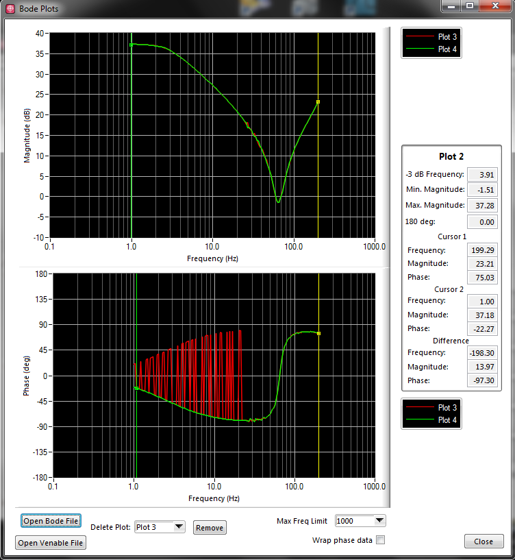
The measurement parameters:
Frequency: Hz 12800
Number of samples: 1200
Tiara parameters:
Values: 4 757 810
Time: 11:24-14:12
To match my data with time in tiara, I divide the number of values between the seconds of the archipelago.
It was my setting, I Don t know if they are correct and I can´t figure out why it shows me frequencys up to 300 Hz.
Thanks and regards.
Hello Rolando-stc,
I've done some tests and I actually reproduced your problem to get frequency much lower than expected with the FFT. The problem is the way you build your weather channel data. ¿WHERE do you get your data points? The thing is that sometimes the data comes in the form of waveform data. This means that these data already include a channel in time in the same channel, so you don't need to generate a time warp to compute the FFT. If your data is a digital channel only, you need not generate a time warp to compute the FFT. How to calculate the time channel is given the sampling frequency of your data. For example, I have a channel with 325000 points, and the sampling rate was 50000Hz. This means that I have to generate a time with a stage of 20 channel (1/50000) in order to obtain a measure of the FFT of 25000 Hz. If I use a stage of 20 with a selection of field time/Step/bib and 325000 as number of values in the window generating weather channel, I get the channel early to use with my data to compute the FFT. In your case, your sampling rate is 12800Hz, which means that no time should be 78.125us in order to obtain a measure of the FFT of 6400 Hz. In your post, I noticed that you have a different time step. On the other hand, you say that you get a total of 4757810 data points. I do not understand how you get this tip with the sampling rate interval and the time you mentioned. I suggest you create a weather channel using the stage early and check that the data points total is correct. You can use a string of hour or a digital channel, it doesn't really do much since you get the same result for the FFT. I hope this information is useful. Don't forget to post back if you have any questions.
See you soon
-
Hi all
I used a signal for a FFT analysis using DIAdem. I have used the following options available in DIAdem:
FFT (hourly)
Windows type: Rectangle
The FFT functions: Amplitude
Amplitude type: power spectrum
Third / Octave = No
Average of the amplitudes: none on average.
I have attached the raw data in an Excel file. In addition, I have attached an image indicating the amplitude versus time plotted in tiara on top. On the left side the data plotted using another software, while on the right side, the data is plotted to TIARA. The frequency on the x-axis is ok, but the amplitude on the y axis is not the same. I would like to ask if there is a way I can get the raw signal of amplitude with tiara, I think it's the normalization?
Thank you
Pepis21
Hello boutique,
Looking at your signal, the amplitude you want to achieve is not possible (unless you change units or you it multiply).
Imagine, if you had a perfect sine wave of amplitude of 1 you should have an amplitude of 1 when you perform the FFT.
Your maximum amplitude signal, you could get would be less than 100 (far 3.5E7)
Best regards
Andrés
-
I should probably Preface that I'm new to LabView and LabView FPGA news especially, so with a bit of luck, it's an easy thing that I am simply on.
I wanted to start with a "simple example" of an FFT on the work of FPGA. It seems to me that the simplest approach is to use the sample project 'Simple NOR-USRP Streaming' and my NO-2942R. This program distributes the antenna RF data, converts baseband and publishes these (decimated) data to the host, which then makes the FFT.
It all works very well.
But I want to spend the FFT for side FPGA of things, and that's where I meet trouble.
I found this (http://www.ni.com/white-paper/7088/en/) and I do not see any problem with my design, except that when I switch to the FFT, I don't see what 0 instead of data, yet apparently from rear switch works great. The problem is that if I have this example to read the data on the side of RF, and there are examples regarding using the FFT, I always get the same result (all 0) when I try to combind the two pieces.
I enclose my VI block diagram. Note all my Special of changes with the FFT, the FIFO in two and pass assistance or bypassing the FFT. Everything else is in the code example.
Thanks for your help!
Had, apparently I missed the connection "Ready for the entry" on the bottom of FFT block. Threw me because he 'built' without it!
Thanks for this example, IronBrotha. While it has not helped with THIS specific problem, it gives me some ideas for my next step which is VERY similar to this example.
With regard to the VI, sorry to hear that it was not complete. I assumed that since I did not add any void live in an example of a default that would work only... but clearly I need to view the file integer lvproj in the future.
-
Bill land - problem with phase
I have a problem of implementation during the attempt to produce traces of Bode for my team designed the hardware. I have now successfully been able to produce the data you expect, with a single question. Part of the phase of data points are the opposite of what is expected. I'll explain the process used...
The material, I log in allows me to inject the signals on channels, but also the flow of these channels of my PC application for analysis. The function that I'm trying to replicate is a frequency sweep, as follows:
-major equipment to replace a channel (the stimulus) with an sine wave frequencies, f
-broadcasting the channel stimulus as well as his response to a certain channel number of cycles, P
-the analysis ("transfer function") on the stimulus and data stream response strings
-connect the frequency (f) with the phase intended to produce a Plot of Bode and corresponding calculated magnitude
-increase the frequency (f) and repeat steps
This code example is 'analysis' performed:
int i, MaxMagIdx, DontCareIdx;
Double * TimeInMag,.
* DontCareArr,
TransferReal,
TransferImg,
TransferMag,
TransferPhase,
DontCare,
AdjFreq;NIComplexNumber * TimeSweepIn,.
* TimeSweepOut,
* FFTSweepIn,
* FFTSweepOut;TimeSweepIn = malloc (gSweepCountMax * sizeof (NIComplexNumber));
TimeSweepOut = malloc (gSweepCountMax * sizeof (NIComplexNumber));
FFTSweepIn = malloc (gSweepCountMax * sizeof (NIComplexNumber));
FFTSweepOut = malloc (gSweepCountMax * sizeof (NIComplexNumber));TimeInMag = malloc (gSweepCountMax * sizeof (double));
DontCareArr = malloc (gSweepCountMax * sizeof (double));int InputSigIndex;
unsigned char OverrideMsg [L_ADC_OVERRIDE_RQ] is {0};.
for (i = 0; i<>
{
TimeSweepIn [i] .reellement = gSweepInArr [i];
TimeSweepOut [i] .reellement = gSweepOutArr [i];
TimeSweepIn [i] .imaginary = 0.0;
TimeSweepOut [i] .imaginary = 0.0;
}CxFFTEx (TimeSweepIn, gSweepCountMax, gSweepCountMax, NULL, FALSE, FFTSweepIn);
CxFFTEx (TimeSweepOut, gSweepCountMax, gSweepCountMax, NULL, FALSE, FFTSweepOut);for (i = 0; i<>
{
ToPolar (FFTSweepIn [i] .reellement, FFTSweepIn [i] .imaginary & TimeInMag [i], & DontCareArr [i]);
}MaxMin1D (TimeInMag, gSweepCountMax, & DontCare, & MaxMagIdx, & DontCare & DontCareIdx);
CxDiv (.reellement [MaxMagIdx] FFTSweepOut, FFTSweepOut [MaxMagIdx] .imaginary,
FFTSweepIn [MaxMagIdx] .reellement .imaginary FFTSweepIn [MaxMagIdx],
& TransferReal, & TransferImg);ToPolar (TransferReal, TransferImg, & TransferMag & TransferPhase);
TransferMag = 20 * log10 (TransferMag);
TransferPhase = RadToDeg (TransferPhase);AdjFreq = (double) ((unsigned long) (gSweepFreq * 0 x 200000000 / (double) 50000000)) * 0 200000000 50000000 x / (double);
fprintf (Logfile_Handle, "% lf\t%lf\t%lf\n", AdjFreq, TransferMag, TransferPhase);
Free (TimeSweepIn);
Free (TimeSweepOut);
Free (FFTSweepIn);
Free (FFTSweepOut);
Free (TimeInMag);
Free (DontCareArr);It works almost perfectly. The problem is that the calculated phase will be positive when there should be negative and vice versa.
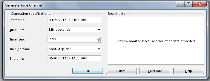
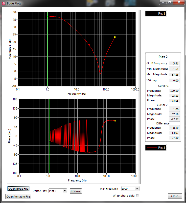
Here's a graph of the data produced:
This is what is expected:
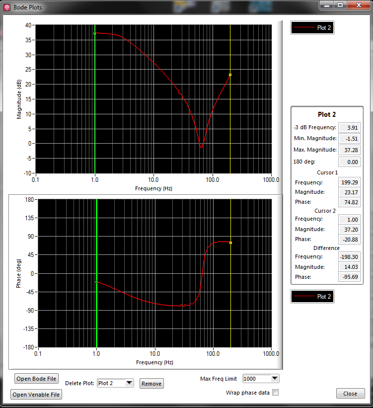
Here are the two bunk:
The expected plot was produced by the log file of cheating. I went and I didn't change the incorrect points to negative values. I want to eliminate this step. As you can see, if incorrect data are reflected on the zero line, it's what we expect. This "expected" given corresponds to what material Analyzer of my colleague (Venable device) when it is used on our device.
We believe that the issue is not with carried out complex math, but a problem in the FFT function or the selection of the index to use on the data table.
Hi PedroMunoz,
It was random semi.
With the help of a licensed physicist with a PhD, the solution was discovered.
When a FFT is performed, the output is a complex signal frequency. Convert this signal complex in amplitude and phase. The signal amplitude must contain a pic. The ridge of the signal amplitude is located at the frequency at which the sample represents. I understood.
However, reading the FFT also of output magntiude contains a second peak. This second peak is negative frequency, and to analyze these data point conjugate complex is necessary. This second Summit should theoretically have the same amplitude, described as:
F (f) = F * (-f)
What interests me in recovering is F (f). What was happening was because F (f) and F * (-f) are theoretically the same (hence, they should the two registry as the maximum value of the table), F * (-f) would sometimes be picked up as the maximum value of the table instead of F (f), perhaps because of the noise. So I just need to make sure that I'm not the negative frequencies in my table.
To ignore the F * (-f), all I had to do was only to watch a half of my output of the FFT. When I change my code for:
TimeInMag = malloc (gSweepCountMax/2 * sizeof (double));
DontCareArr = malloc (gSweepCountMax/2 * sizeof (double));for (i = 0; i
{
ToPolar (FFTSweepIn [i] .reellement, FFTSweepIn [i] .imaginary & TimeInMag [i], & DontCareArr [i]);
}
MaxMin1D (TimeInMag, gSweepCountMax/2, & DontCare, & MaxMagIdx, & DontCare, & DontCareIdx);I'm ignoring the negative frequencies. By setting the parameter 'shift' of CxFFTEx to FALSE, it organizes the positive frequencies in the first half, then the negative frequencies in the second. I pick up is no longer the wrong index, which would result in the phase reverse reading.
I hope this helps someone else in the future!
-
Detection of overruns of vibratory limit with FFT
Hi all
We follow a piece of rotating machinery for vibratory limit overruns. Our acquisition of digital data is running at 3333Hz with anti-aliasing in front of the ADC analog filters. We sample at least 5 times on the highest frequency of interest. We then duplicate the measured data and apply several sets of filters band pass to divide the specrum in several frequency buckets watching us then for exeedences the limits defined.
We head to dedicated hardware for our analysis of the frequency of a solution all digital. I have a display FFT showing the linear magnatude of the signal over the frequency. Then, I want to implement limit control on the output of the FFT for real-time tracking. We will always post our data in frequency bins and will have a second look to limit cost overruns after the fact.
As most seems, I had trouble doing exact enough amplitudes of the FFT. Not sure if my problem is spectral leakage or a total lack of understanding FFT. I think it's the latter.
My sample VI has a capture of dynamic data with a real overtaking in the bandwidth of 4-50 Hz. The limit is 5 across. Amplitude in this bandwidth was almost 10. I've included a screenshot of exceeding the limit on the face before of the VI for reference. I have also indexed data saved to the point where the excceedence is visible on the raw data.
I tried using a FFT to visualize this limit so that I can detect the overflow, but I have not been successful. FFT tried several methods and all do not reach the height. Those smarter than me could give it a try? I don't want to run multiple filters of past band by signal in real time, as we do post-processing. I am trying to monitor and display data between 8 and 24 channels. I am concerned about the limits of my processing power to stand in a real-time environment close.
Thanks for the help! And I would like to know if it's just the misapplication of an FFT and if something is better in order.
-Chris.
Lynn,
Thanks for the reply! I tried the inverse FFT road as well, but my implementation was nowhere as clean as yours. I had to spend your complex 1 d inverse FFT block to match the data source however. The actual parameter was twice the amplitude of output. Update attached VI.
I like this solution and you will use Fortunately!
I have an another question though. My company uses not rms. All our limits are in peak (peak-to-peak) / 2. We can also assume that all the waveforms are sinusoidal and so impossible to convert from rms to crete with a root of 2. I'll need a FFT function that does not export in rms. In Matlab, our guys had to code our own FFT function as rms output all built-in functions.
Any ideas on where to find a FFT function that does not export in rms? Annoyingly, I need then inverse FFT in rms as well to match.
-Chris.
-
Hello world
I have some general questions about FFT on FPGA and the resolution of frequency spectral analysis.
To establish understanding:
I want to read the frequency with fs = 500kS on my FPGA. The FFT of the FPGA palette function allows a maximum of N = 8192 samples. This results in a resolution of frequency of fs/N = 500,000/8192 = 61 035 Hz and a bandwidth of fs/2 = 250 000 Hz.
My destination in spectral analysis is a resolution of 1 Hz in the range of 9 kHz to 11kHz.
My questions:
1. is there a similar function for FPGA as the 'Zoom' FFT applications in Sound and Vibration toolkit or can I use it on the FPGA target-VI?
2. is there a code for another example ' overlap and add ' or ' overlap and save "-method for the Fourier Transformations on FPGA?
3. any other suggestions for the problem described?
Best regards and
Thanks in advance
Sow
Hello Scott,
The result of your calculation is correct, you get a frequency of 60 Hz about resolution, but how you calculated it is false. If you sample with 500kS/s you can have a maximum of 250 kHz and FFT frequency you'll 8192 lines in your spectrum, so theoretical, you would have a resolution of about 30 Hz. But the FFT on the FPGA is both sides, that is, it returns the positiv and negativ frequencies. You cannot use the negaive ones, so you have only 4096 lines left from where you get a frequency of 60 Hz resolution about.
That being said there is no Zoom FFT for FPGA and you cannot use the Express VI of sound & Vibration TK here.
So, if you need the frequency upward to 11kHz, you could decimate the data and samples with 22Ks/s, then you get a 2.7 Hz resolution.
With a fixed block size you can get a better frequency resolution to measure a longer time.
Hope this helps,
Christian
-
Hello
I built a vi that performs the FFT of a signal (~ 200,000 admissions in a 1 d table), during its operation, I'm not sure it will output the correct answer (or at least it is not sensible for me).
I'm trying to find the frequency of distribution. The signal was acquired to ~ 200 Hz. A screenshot of the output and the vi are attached.
Any thoughts? I really need help with that.
Thank you
simply_me wrote:
Rest only one problem - the two scales of the horizontal and vertical axes (horizontal must be frequency), no idea on how to change it?
The link does not show how to handle this issue (of index instead of the time domain).
You must set the increment of the x axis to reflect the appropriate units.
For the chart of field time, 1/200 and for the field of frequency to the derived value as described above.
You can set the increment of axis in many ways:
- Manually via the properties of the chart (-right click...) Properties)
- Via a property of the graph node (X - scale.multiplier)
- By grouping as illustrated in the city figure 25.
-
The purpose of my program is finally take a random signal with a length of discrete and display the fft with Windowing and applied average signal. In the VI attached to this post, I took a sinusoidal signal and treated with an average and not an average. The signal averaging produces an incorrect spectrum.
It would be appreciated if someone could let me know why the spectra of the FFT on average and not average are not the same and tell me how to improve my code to produce the same spectrum of instruction.
A potential problem is that the resolution of frequency of the FFT is function of the number of datapoints in the FFT. Also the relationship of phase between the different segments can vary depending on how your segmentation works and how many segments you define. With window, this can be a problem because the effects of windowing the amplitudes of the sample data at the ends. And with no windowing, it has spectral bleeding.
Mike...
-
FFT Error 2015 LabVIEW with crew
I was invited by my work to upgrade to the production floor. Our production is currently using labview 2012 with about 20 different testers on this. I downloaded and installed labview 2015 runtime and installed on all machines that are needed to upgrade.
However I noticed a mistake that I can't explain. For some reason, when im trying to build an executable of some testers that have been made by a third-party testing company I get some errors of markup upward. These errors do not appear on the code that we have developed in house, its only third-party programs that are these errors of markup. I have attached a photo of the errors. The other mistake bed
«Labview: resource not found.»
An error occurred loading «NI_MAPro.lvlib:ma_FFT with Hanning.vi» VI
LabVIEW support 3 error code: could not load façade. »
I have raised a request for assistance with National Instruments, but it's looking like they're not too sure whether. Anyone have any ideas on what I might try?
I have re-installed labview, re-installed the run-time engine, tried several pc and he always comes back with this error. I checked the dependencies between the two and the location for NI_MAPro.lvlib is exactly the same, there seems to be some indifferences, so I can't explain as to why I get this error.
Thanks a lot for any help
Colin
When you created the executable in 2015, you also created an installer for it?
You say that you have downloaded and installed the runtime of 2015. But I think the executable needs something that is not a part of this performance. My first guess is the lvanlys.dll.
Try to create a simple VI that comes is a simulation of signal and filtering and an FFT. Create and .exe and try to run on other machines to see if you still have a problem. If you do, try to create an installer for this simple executable file and then run that. See if you still have a problem. Then see if you still have a problem with your actual executable file.
-
The FFT LabVIEW uses the usual term of eponential:
e ^ (-i * 2 * pi * k * n/N)
Is it possible that I could change this term to include a constant and perform the FFT as usual? that is to replace the exponential term above with something including a constant 'c ':
e ^ (-i * 2 * pi * k * n * c/N)
I actually use a 2D on a square table 2D FFT, but hopefully a solution to the case 1 d above would be easy to apply.
If it's more math than the programming problem, a point in the right direction would be always greatly appreciated!
The only parameter that you can control is N, the number of samples in the dataset. You can try to do 1/N ' = c/n. See if this will give you the results you expect. If c < 1,="" then="" n'=""> N and fill the input data will be required. For otherwise, a reduced supply is necessary. Pay attention to how the data is compressed so that you don't miss any information.
Lynn
-
How to find the ratio between the two frequencies in the fft
Hi, I'm Jean,
I need to find the ratio of the frequencies of 1st and 2nd graph fft.
Already, I received information of this site only. Mr. Alten helped me.
Now, I have to continue the same problem and need to find the ratio of the frequencies.
Please someone help me guys...
I will attach my vi file and the text file.
John,
Should you report the frequencies or the report of the amplitudes of the components at these frequencies?
The Information.vi of your multiple for the Signal Processing, extract > range of measures of waveform should do what you want.
The frequency resolution is not very good because you have cycles relatively little waveforms (2 ~ for the lower frequency). I added a few zeros to improve resolution, even if a larger sample of data would be better.
Lynn
-
FFT vi truncate the FREQ of signal.
Hello
I noticed that the FFT vi truncate my signal. See attachments.
I'm basically the noise of a signal (I have both the phase - I - and out of phase - Q-signals...)
(Ignore the vi curve, it is just to remove the continuous component of the signal, it's irrelevant to this discussion).
Kind regards
Ali
You lose your calendar information for data going to the graph of the PSD. It works on arrays. The FFT functions assume a dT or dF 1. So when things are placed in the chart, you will see values up to 0.5 since Nyquist limits you to 1/2 of the sampling frequency. PSD2 graph doesn't have this problem because the blue wire of the DDT keeps the calendar data.
If you build your table in a type of waveform data and the boot in the value of dT, your data should look like the other graph.
-
FFT signal who read analog spindle by Arduino
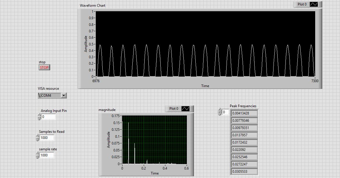
I use Arduino to send my signal to Labview. The signal display on the table good enough, but I could not achieve its spectrum (I'm testing with Vpp = 1 to 100 Hz sine wave).
What should I do to see the spectrum? I think (after ADC_Read function) output signal is quite different from others.
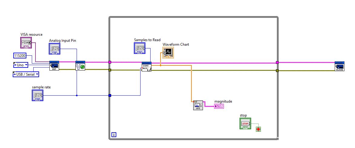
I hope someone can help me with this problem. Please, I really need your help. This is my final project!Attached, this is the Panel front and block diagram understand signal (don't care signal had only half higher due to the ADC_read, this isn't my problem) and the spectrum. Problem is that I do not understand why is the spectrum and how to fix it?
holucbme wrote:
Hi, RTSLVU
I use Labview for Arduino (LIFA) interface. I can fix the code in the firmware, bro?
Also, can you show me the above problem? (the FFT was inappropriate at 100 Hz)
I didn't know you guys were related.
Connect your graph of waveform over waveform after generating in the dT instead of the array of doubles. It will show the graph of calendar information rather than just integers on the X axis.
Are you sure that your input signal is 100 Hz? Are you sure that your Arduino is acquireing at 1 kHz?
-
I use Signal Express but this issue applies to any software. I hope someone can help us with that. I use a card OR-9233 to measure acceleration. I put my 25K sampling rate and put a filter of 10K. I use the software to trigger.
My setup is the accelerometer mounted at the back and the back of the handle of a hammer (down where you would hold it). I was asked to measure the outcome when a small steel ball fell (slightly) to the shock of the hammer head. The accelerometer is a PCB brand 1000g pezioresistive accelerometer, (mechanical BW around 10 kHz).
My question is this: is it possible to perform an FFT when you are just going to "hit" the hammer and measure the result? I'm not measuring the real impact, only the vibrations after it is hit. When I taste, let's dire.5 seconds, I get a nice time signal, and then I apply a FFT. When I shorten the time of acquisition to 40 milliseconds, I'm obviously only enter the beginning and my looks different FFT (highest magnitude), so I started to wonder what is "real"? Operational entities designated and required a repetitive signal of the FFT? Is there a limit to how many "small" or "large" of a time signal that I have?
Looking for some general guidance as my name of field time - frequency domain skills are so right now.
I have the ability to use a sensor to measure impact energy impact, but it is a large sensor. My accelerometer is small. I'm up to the side of the accelerometer AFAIK. I'm wasting my time with a FFT?Kind regards
Jeff Scharpf
Jeff,
Ok. You have a definition of the problem: say the guy marketing you can measure a difference between the two handles.
I guess that both use the same head and the head is solid metal and the handles are of different materials.
You have a way to generate a coherent stimulus. If you always to clear the ball from the same point, you should get a fairly coherent excitation of the hammers. It is possible that the way in which the hammers are hung in the framework could affect the results, but my guess is that this will be a minor effect.
I guess that the answer of the head is a complex resonance excited by the impulse produced by the ball. It will be complicated because the form of the hammer head is asymmetric (unless it's a hammer) and due to the load produced by the handles.
I'll try to measure the reaction of the accelerometer in a few places on the head of the hammer (places where he could not get hit by the ball!). If you can get something that's fairly consistent between the two hammers here, so you have a reference for comparison purposes joint entry. If the answers of the heads are very different, so it will be harder.
Then, I would look at the response of the handles in comparison to the heads. Two accelerometers, an on the head and the other on the handle, measured at the same time are ideal. I would look for differences in depreciation. In other words, the ring die down more quickly on a handful than the other? It is a measure of time, but it may require that the filter to select a unique resonance at a time. I think you want to get as much data as possible, the second half or more as you mentioned earlier. Short segments may be more difficult to interpret and not have al the information you want.
If you can post data, a person may be able to give some other ideas.
Lynn
Maybe you are looking for
-
Can not stop auto update latest firefox version
Hello I googled a lot of answers about stopping the automatic update of firefox. But unable to do it and not be able to use the functionality offered in the context of the browser. I have to do this deliberately to have my selenium framework support
-
Context menu (including all the other menus) does not work after a while.
I use ubuntu 12.04 LTS, 33.0 firefox (thunderbird also same problem). Context menu and all menus are not works after a while (maybe 30 min)? I have to close all firefox windows to make the menus work (make an another new firefox windows does not solv
-
Problem with satellite L40 12 X graphic card
Hello, I have a problem with my graphics card. I have not now how to enlarge the memory video it s. Physical memory: 1015 MBMinimum graphics memory: 8 MBMaximum graphics memory: 224 MBUsed graphics memory: 9 MBProcessor: x 86 family 6 model 14 Steppi
-
Pavilion J410: supported printer/scanner for Windows 8.1
Hello 8.1 Windows does not support my printer/scanner HP J410. It works on my laptop, but it's a pretty prehistoric, with Vista OS. So, what can I do for that device installed on Windows 8. 1 as well?
-
Why my PC now starts with black background and not authentic message?
Original title: why PC starts in Mode safe? I have Microsoft Windows Vista Home Premium 64-bit Edition. Before going on vacation, I turned off all power. After that we are back and turned on PC, system booted in safe mode. Screen has black backgroun