FFT
Hi I'm using labview 7.1
I have an output of a device in an excel file. (which is basically voltage v/s times)
Now, I want to perform an FFT on this data, IE. I want the variation in the signal in which the frequency instead of time.
How do I do this in labview?
NitW wrote:
I used the ' FFT (phase-Mag) vi. Now, I wanted to record these 2 outputs (amplitude and phase) in a spreadsheet file. I am not able to directly use the "save to spreadsheet vi'"
You need to unbundle the tables 1 d mag and phase (see picture), built into a 2D array, and then write the result into a spreadsheet file. Converts if you wish.

Tags: NI Software
Similar Questions
-
Hi all
In my application, I'm analyzing a beep.
I used the spectral measurements vi for the FFT peaks.
Now I want to know the number of instances in which amplitues is over a certain limit, say 0.01.
Since I'm not an expert, I could really use some help.
I enclose my vi with a sample sound file.
Thank you
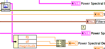
The result of the power spectrum is an array of clusters. Each cluster has three elements: f0, df and a variety of sizes. Ungroup all elements, use the table with a ridge detector function. Multiply the 'locations' with df and then add f0. The resulting table contains all vertices with the configured threshold already set on the frequencies to migrate.
Norbert
-
Using FFT to palette spectrum Subvi Interface of FPGA functions
Hello
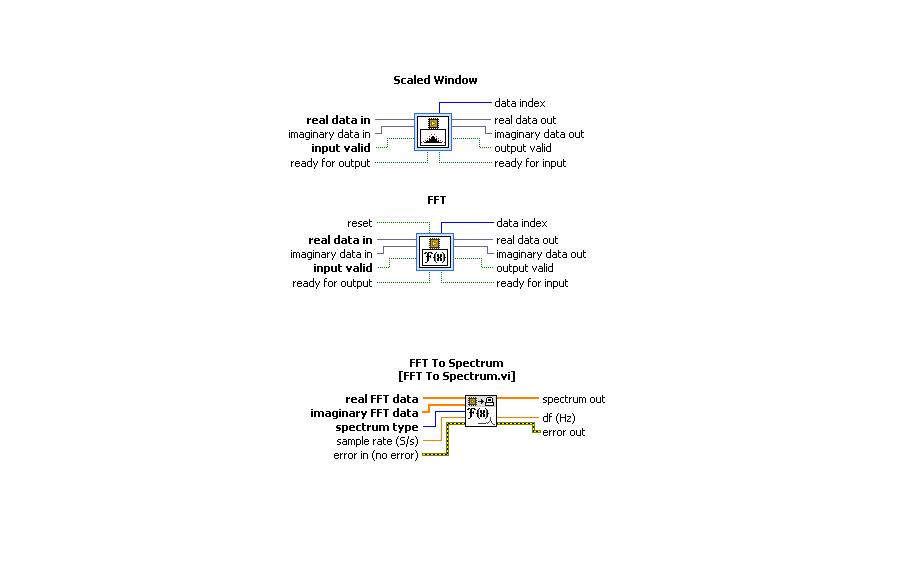
I use the card PCI-5640R and PXI-5600. I want to use the "scale" and "FFT" exspress screws to the range of functions 'Mathematical FPGA and analysis' in my VI "FPGA VI" and "FFT spectrum for '"FPGA interface"in my"host VI.
A poster of the code examples in which these three subVIs are used can.
Thanks in advance.
Kind regards
Rashid
Hi rachid,.
There are two examples of delivery here: LabVIEW 2009\examples\R Series\FPGA Fundamentals\Analysis and Control\FFT\
Jim
-
Hello world
I have copared the original FFT for LabVIEW and MathScript algorithm execution.
To do this, I calculated a 128 k TFF 100 times. The necessary calculation by MathScript time
is 4 - 5 times higher. I used a very simple MathScript code that calculates just the FFT,
No loops, etc. that were involved. Anyone know a good reason for this? It cannot be explained
through the exchange of data between LabView and MathScript. MathScript uses a less efficient
FFT algorith that LabView?
Thank you
Ulf
-
Error 1074396120 has occurred to IMAQ FFT
Hello. I'm new here. I am attaching a file VI here that there is a mistake once I try to filter my loaded image. The error occurs on IMAQ FFT and he says, it takes a picture. Can you please help? Thank you.
version of 2013.
-
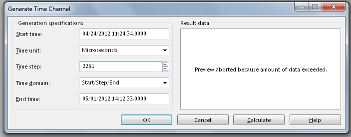
Hi, I work analyze signals of vibration thanks to tiara, data are from 4 to 5 million points in three or four hours, the problem is when I run the analysis FFT only shows me frequencys up to 300 Hz when I know that I measured frequencys of 3 500 Hz.
The measurement parameters:
Frequency: Hz 12800
Number of samples: 1200
Tiara parameters:
Values: 4 757 810
Time: 11:24-14:12
To match my data with time in tiara, I divide the number of values between the seconds of the archipelago.
It was my setting, I Don t know if they are correct and I can´t figure out why it shows me frequencys up to 300 Hz.
Thanks and regards.
Hello Rolando-stc,
I've done some tests and I actually reproduced your problem to get frequency much lower than expected with the FFT. The problem is the way you build your weather channel data. ¿WHERE do you get your data points? The thing is that sometimes the data comes in the form of waveform data. This means that these data already include a channel in time in the same channel, so you don't need to generate a time warp to compute the FFT. If your data is a digital channel only, you need not generate a time warp to compute the FFT. How to calculate the time channel is given the sampling frequency of your data. For example, I have a channel with 325000 points, and the sampling rate was 50000Hz. This means that I have to generate a time with a stage of 20 channel (1/50000) in order to obtain a measure of the FFT of 25000 Hz. If I use a stage of 20 with a selection of field time/Step/bib and 325000 as number of values in the window generating weather channel, I get the channel early to use with my data to compute the FFT. In your case, your sampling rate is 12800Hz, which means that no time should be 78.125us in order to obtain a measure of the FFT of 6400 Hz. In your post, I noticed that you have a different time step. On the other hand, you say that you get a total of 4757810 data points. I do not understand how you get this tip with the sampling rate interval and the time you mentioned. I suggest you create a weather channel using the stage early and check that the data points total is correct. You can use a string of hour or a digital channel, it doesn't really do much since you get the same result for the FFT. I hope this information is useful. Don't forget to post back if you have any questions.
See you soon
-
Why Express PSD gives a different result of amplitude as FFT PSD?
Hello
When I use the express VI of spectral measures to trace the power spectral density, I get a different result than when using the FFT PSD VI. The data are the same but the amplitudes are different in the PSD plot. Everyone comes through this?
Thank you
Donners,
The PSD2 and graphic PSD2 are different because you are breastfeeding two extra points in the tables (t0, df). When graphic entry of data in the tables, they interpret not automatically information of t0 and df. Actually they do not yet receive this information. You must program the scales with nodes of property. If you simply draw the order of magnitude, the spectra are very similar.
^ ^ ^ This confuses only the chart!
The spectral forms differ slightly as the power spectrum of FFT and PSD.vi uses a default Hanning window.
Lynn
-
Hello
I use DASYLab V11.0.1 on a WIN XP SP3. I want to use the following worksheet for a long time measurement. (Here you see no entry, it is a simulation)
To reduce the measurement data, the shell acquisition depend on events.
If the entries (Signal_offen AND Signal_zu) have a low TTL, the data must be saved.
Othervise the shell of data recorded hourly for 6 seconds (controlled by the Impulsgebe00 Module).
The spreadsheet works so far, but if I want to analyze the first three entries with a FFT Module, I get the message "illegal block size. Stop. "when the 'relay' nearby.
(Low - TTL to the input of the relay control; see "Trigger-Anze")
I hope you can help me. Or maybe someone has another solution.
If you solve (4) value of incomming block = xxx with this change so that you can use the data flow of the module with relay and FFT.
-
I should probably Preface that I'm new to LabView and LabView FPGA news especially, so with a bit of luck, it's an easy thing that I am simply on.
I wanted to start with a "simple example" of an FFT on the work of FPGA. It seems to me that the simplest approach is to use the sample project 'Simple NOR-USRP Streaming' and my NO-2942R. This program distributes the antenna RF data, converts baseband and publishes these (decimated) data to the host, which then makes the FFT.
It all works very well.
But I want to spend the FFT for side FPGA of things, and that's where I meet trouble.
I found this (http://www.ni.com/white-paper/7088/en/) and I do not see any problem with my design, except that when I switch to the FFT, I don't see what 0 instead of data, yet apparently from rear switch works great. The problem is that if I have this example to read the data on the side of RF, and there are examples regarding using the FFT, I always get the same result (all 0) when I try to combind the two pieces.
I enclose my VI block diagram. Note all my Special of changes with the FFT, the FIFO in two and pass assistance or bypassing the FFT. Everything else is in the code example.
Thanks for your help!
Had, apparently I missed the connection "Ready for the entry" on the bottom of FFT block. Threw me because he 'built' without it!
Thanks for this example, IronBrotha. While it has not helped with THIS specific problem, it gives me some ideas for my next step which is VERY similar to this example.
With regard to the VI, sorry to hear that it was not complete. I assumed that since I did not add any void live in an example of a default that would work only... but clearly I need to view the file integer lvproj in the future.
-
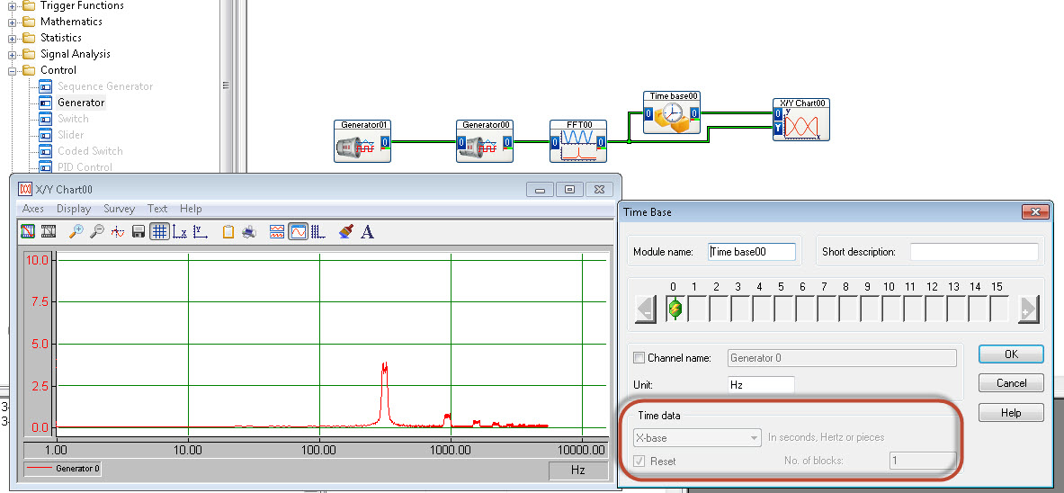
FFT to display with newspaper frequency axis
Hello
I'm trying to get my fft to display frequency (x axis) with a logarithmic scale.
There is no option for this in the table y/t
The xy graph has possibility of HRT, but I cannot "demux" the fft output signal successfully.
I use DasyLab 12.
Someone at - it ideas?
Thank you
Matt
Use the time Base module (special offer) to extract the x axis out of the block of the FFT.
-
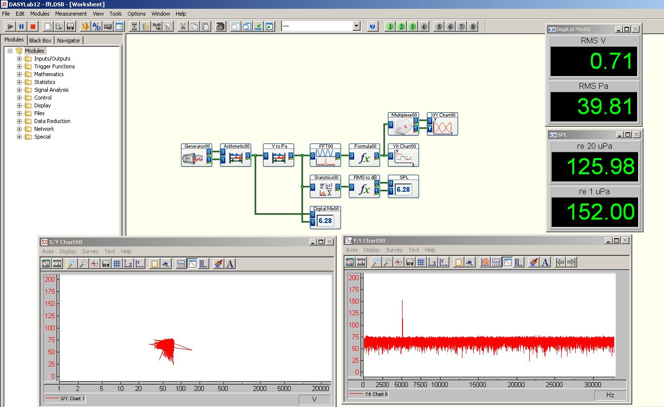
frequency of the FFT is not compatible with matlab
Hi all
Please find .jpg in the attachment. The signal is generated by a signal generator and collected by datashuttle/3000. Then I use the "FFT module" and "statistical value" to find the position max (frequency). I also downloaded the data and processed by matlab FFT function. What I find, is that the value of the frequency of dasylab is always slightly less than matlab. For example, when the signal generator gives 10 Hz, the dasylab indicate 9,77 Hz and matlab gives 9.99 Hz I used matlab for years, so I have confidence in it. There must be something wrong with my program or dasylab. First I have is because of the resolution, so I changed the "statistical values - mode - based block and tick (not quite sure about this) parent block and a value for every 240 blocks, which is also for the sampling of matlab." Unfortunately, there is no change at all. Can anyone help?
Thank you very much
Alan
What is your size of rate and sample block DASYLab?
Try to make the block size an even number, for example, if you sample at 1000 Hz, made the size of the block 500 or 1000.
What is the equivalent block Matlab? The amount of data is used for the calculations.
You can also use the module block average average more than 250 blocks and then use the module of statistical values to calculate the maximum Position.
-
Hello everyone.
I'm having some trouble for my project.
I would like to apply the Fast Fourier Transform on data acquired by an accelerometer. I do measures of vibration, data entry is a string it is then cut into the values of the axis 3 and converted into numbers.
What I would like to make is the FFT of these data, but I don't know how to "transform" waveform to apply the transformation.
Any help is appreciated.
My VI, commented, is attached.
Dear AndreasSchnaas,
Try the "worksheet to an array of strings.
To enable a detailed response, record the value by default in your orders and indicators data and post your VI once more. Data can be collected using your VI, unless the equipment is available for the user.
See you soon,.
-
FFT and differ from the values overall btwn VI and tiara
Hi all
I have an application that displays live readings of vibrations which the spectrum and the overall vibration level. Everything my generation of report is made in the DIAdem scripts, so it is essential that all values calculated and displayed on the side of LabVIEW are the values calculated and reported in DIAdem. The VI and Script, when the entrance to the PDM attachment, attached give me values significantly different to the size of the FFT and the overall value of RMS. Can anyone spot what I'm doing wrong?
Thank you
Scott
Hello
This is an excellent response of R & D. I felt that it would be better to put it on the web, then keep it limited to your service request.
The difference has to do with the window of correction. The results are the same if you choose rectangluar (or not) window.
Usually a window takes a share of the singnal away, so in the first place, the result has a different shape and is smaller compared to train with rectangular window. This can be fixed with a specific factor for each window.
There are two possible corrections. Random and periodic.
-Periodic is used if you have pure sinusoidal signals and you want to measure the peak value. A typical use case is the window of flattop is designed for this type of calculations. The periodic correction is too great if you want to add values to calculate the total RMS signal or the sum of a certain frequency band.
-Random is correct the signal back to the correct overall RMS value and must be used in all other cases.
The periodic correction for Hanning window is a factor of two. The correction is randomly about 1.633. Tiara will give the same result as LabVIEW if you use the following type of correction:
FFTWndCorrectTyp = "periodic".
In the world of the FFT analysis, the different corrections are very often not obvious and hidden to the user. Unfortunately, it is also the case in LabVIEW. You can find a good example of explanation here:
http://blog.Prosig.com/2009/09/01/amplitude-and-energy-correction-a-brief-summary/There are different factors for different window functions. If you go further in the FFT - VI you will find "window scaling VI. It has a «constant window» output With this, it is possible to obtain the correction values for window functions.
I think also, periodical is false in most cases, when Hanning is used, because Hanning is the best for the sum of the values of the RMS in the frequency bands and the results are bad without a correction at random.
Hope that helps.
-
FFT (up to harmonic (n) of the 2D array
Hello 150,.
I want to record a FFT for the specific frequency range. The entrance is a 2D table in which each row represents a record. I just need phase und amplitude of the harmonics (up to the n - controllable). I didn't need too many harmonics, so I would avoid calculations and do to the amount of certain frequencies in the FFT.
I would take this VI, but y at - it an option to set a range for the FFT? Or another VI accesses Magn. & Phase for harmonics?
https://zone.NI.com/reference/en-XX/help/371361H-01/lvanls/amp_and_phase_spectrum/
VS_03 wrote:
... (or is there a better way?)
Well, if you know exactly the spectral positions and the data are clean (no spectral leakage, without periods truncated, etc.), all what you need to do is multiply with the waves of the complex unit of frequency. (See also this for the amplitude of the fundamental frequency, can be easily added for more spectral positions.) Note that the FFT is very effective, so if you need a large amount of spectral positions, it might be faster.
-
DSA 4461 FFT on both channels simultaneously
Hello. I use card PCI 4461 DSA and am currently power density measures (FFT) on both channels simultaneously.
I found the example of the case acoustic and vibrations, but it is only for a single channel.
How can I do to measure 2 channels? I have to add a channel more 'DAQ - mx create a channel' vi series?
I don't know how vi DAQmx REad it would handle. I have had 2 channels for voltage using Express VI.
Thanks to Labview 8.2
Thank you
I advise to use extensions on your DAQmx task to select multiple channels. When you select the physical channel, choose Browse and a list of all available channels will be filled. Hold CTRL and click on different channels to add to your task. See the attached pictures if you have any questions on how to do it.
You can choose to display these data on a single waveform chart, or you can split the signal and analyze each channel separately. Try this and see if it works for you.
-
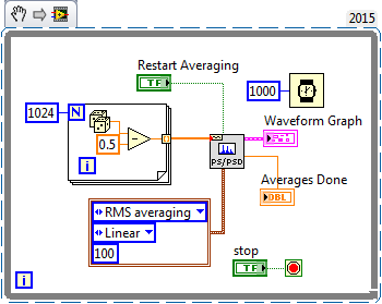
What does not restart in the FFT functions way?
Hi all
I would like to know what that "restart average" made for the FFT functions. According to aid,"reboot on average indicates if the VI restarts the process chosen medium." If restart on average is set to TRUE, the restart of the VI the selected with an average of process. If reboot on average is set to FALSE, the VI does not restart the process chosen sprawl. The default value is FALSE. When you call this VI for the first time, the averaging process restarts automatically. A typical case when you need to reboot on average is when a major change of entry occurs in the middle of the averaging process"
I realized that the FFT function takes in an array of values and perform the FFT on it. If the FFT function keep a buffer previous values and clears when restart average = true? Because the FFT functions are not Point by point and they take both in all the data to deal with, "a major change of entry occurs in the middle of the averaging process" can be true?
Thank you!
Sigh. I really tried to explain what was going on (probably) with this function, you use (and, I thought naively, you understand), but you got me wrong.
This VI creates a zero average noise signal, providing 1024 points per second. Do you know what should be the power spectrum of the signal? Due to the randomness of the input signal, the power (for a small finished sample) spectrum will also have a random component. If you had several ghosts of power on average, the average would begin to converge with the expected for random noise power spectrum.
If you run this VI and look at the Spectra resulting (on average), you will notice that the first spectrum is the most "spice" and that spectra are averaged, the variation is reduced and diminishes the value of crete (shown by looking at the scale of Amplitude). At any time, you can press "Reset average" and see this... reset the average, the following spectrum shows the growing nose, etc.
It shows the right way to test the function of the power spectrum and discover what he does. My suggestion as to what makes this function seems to be largely correct.
Bob Schor
Maybe you are looking for
-
HP Base system device - no driver found
HELO HP customer, Can you help me please how to manually download and install the following drivers of insttaller missing for my computer hp laptop? I tried several times, but the automatic update of the driver could not locate the missing device dri
-
My biggest goal on my t5 eos not autofocus, help
I have the canon eos rebel t5 and my smaller lens focuses very well but when I try to use the larger lens to take better pictures is focused quite
-
Administrator password has changed, unable to connect to the Windows XP system
Original title: my administrator password has been changed by my ex-girlfriend and now I can't do anything on my laptop CAREB running windows xp, how can I fix I do not have the administrator password broke up with my girlfriend she has changed every
-
HP Pavilion 15-e034tx: RAM notebook computer compatibility
This RAM will be compatible with my laptop HP Pavilion 15-e034tx?
-
Hi all We have 3 WLC 4402 all with identical config and we use Lobby Admin to create guest accounts. Problem with this is that the guest account must be created on 3 WLC. I installation WCS and want to know how to extract the 3 existing wlc and their