Filter Laplacian LabVIEW
I've just loaded LabVIEW 2013 and Vision Module 2013, although I have used LabVIEW for years.
I have a project that requires a machine vision.
I launched the Vision Assistant and some of the tools used to see what might work.
I found that it apply the filter, the Laplacian edge detection, get me one step closer to the identification of the edge if necessary.
Then, I went to LabVIEW and created a VI to capture images from the camera (with the help of examples of course).
I can view the image on the screen.
Then I went looking for the VI vision that applies to treatment Laplacian edge detection.
I found the filters and the edge detection, but I don't see how to filter the Laplacian I used the Vision Assistant.
What Miss me? Where can I find this tool in LabVIEW?
Thank you
Jeff
The Lapalacian filter and all the others are created using kernel convolution vi.
Why not just use you Vision Wizard to export your LabVIEW code script? Then, you can take a look inside.
Tags: NI Hardware
Similar Questions
-
filter function of Matlab to filter of labview
Hello
This code matlab read wav file and filter them
[x, fs] = wavread ('apple11.wav');
intrigues secondary (121), plot (x), title ("x wave 1');
XX = double (x);
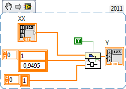
y = filter ([1 - 0.9495], 1, xx);
I have xx table in labview.
now I want to filter them even as in matlab,.
... anyone know how to do this?
Please help me...

MATLAB help tells you:
y = filter(b,a,X) X vector data with the filter described by vector numerator coefficient b and the denominator of the coefficient vector onefilters. If (1) is not equal to 1, filter normalizes the coefficients of the filter (1). If (1) is equal to 0, filter returns an error.
now take a look on LabVIEW IIR digital filters
-
low pass filter in labview 7.1
Hi all
I would like to ask about the low pass filter.
Is it possible to make a simple low-pass filter without any supplement on Labview 7.1.
We strive to connect a micro-switch in a DAQmx device, but the thing is, because the switch is somehow Earth-connected to an engine step by step, each time the engine is running, it will have peaks and spikes were interpreted as logic 1 in the labview. Since we have no treatment signal Add ons in the labview, we try to do it ourselves.
Thank you
Although suggestions are significant
But the solution has not been reached. So actually, we tried to change the analog to digital input in our DAQ hardware. I hope that the - top-of-10V-spike not to spoil our DAQ hardware. And it turns out OK. In the digital input, spikes has appeard not even once, and we think it does.
@ t06afre: thanks for the material made up the suggestion, but since it is a testbox.foobar.com that we, his isn't going to be easy to put in engines and unlikely capacitors supposed to do. The cable twisted pair is not a bad idea though.
We thought that the software solution filter would be the best (less time necessary and less messy) but is not as we have not thought of material assistance (R - C circuit, duuh) filter.
And on the 'minimum pulse duration' setting, is not only applicable for some DAQ hardware? CMIIW
-
How to create a filter by using the function of transfer mathscript in labview
Hi all
I am currently designing a filter in labview using a Mathscript loop. The filter can be represented in the transfer function. I have attached the equation of transfer as well as its value function and the desire of graphic amplitude vs. frequency should I got to it. Also, here is the transfer function written in Matlab.
B1 = tf ([57.5221845], [1 51,017077 205.1868]);
B2 = tf ([1 0], [7.6991]);
B3 = tf ([1 0], [14.32433403]);
B4 = tf ([1 0], [137.6017]);F = B1 * ((1+B3)/((1+B2) *(1+B4)));
Plot (F)
I also change the encoding as Labview Mathscript does not support Matlab coding "tf" as function of transfer to "bilinear".
I am facing problem to are:
(1) cannot display the graph of the labvie filter.
(2) cannot have sinewave as an entry in the filter.
(3) the output can not be display in graphical form.
We hope to have the earlier response of you guys. Thanks in advance

I have attached the version 8.5
-
How can I filter the noises of thermocouple using a TC-2095 and SCXI - 1102c?
Hi all
I currently have four TC - 2095 s connected to the SCXI - 1102c inside an SCXI-1001 chassis cards. These thermocouples are floating and I get a good amount of noise (400 Hz 3 phases and same 60 Hz noise) when we turn on some equipment such as fans, and fans. Using this current set up, how can I filter the noise? Or I would need to put in place a new hardware configuration (e.g., the SCXI-1102 cards)?
Hi RALoo,
The 1102 C has a lowpass filter with a cutoff at 10 kHz frequency, so you will not be able to filter into the material with your current configuration.
Your first option is to use a software filter. LabVIEW has several functions that do this. More information can be found here: http://zone.ni.com/reference/en-XX/help/371361J-01/lvanls/filter_vis/
The second option would be to change to SCXI 1102 cards as you suggest. The low-pass filter of the 1102 was a cut-off adjustable to 2 Hz frequency, which will stop the noise of 400 and 60 Hz don't affect your readings.
-
Filter for table data, the range of data obtained and defined 2D
I produce data of an ultrasonic sensor at 1 K Hz, and there is a lot of data (data points range of 0 to 10). However, in some cases when I know that the data should be about 7 (for example) I get outliers (about 9 and 10). Is it possible to define a filter for data in the defined range.
I averaged the data to get an average value, and outliers are distorting. In the worst case, my outliers are 30 to 40% of the data generated. I created a filter to sort the data and, taken from the lowest value. I stop the loop when data reaches a value greater then 9. But this seems to take a long time (because the loop checks for each data point and there are 1000s of them).
Is there a better way to filter data and define a predefined table range to collect?
I enclose my filter.vi... and a set of samples of my previous data. The ranges of data of 10-8 and would like to have the range 7.5 to 8.5 to consider. The sensor records tension here and the problem can be solved by installing a different type of sensor, but if a filter in LabView can due it, the sensor that we use now is absolute.
I am in kind of emergency, my design in unfinished because of this problem, if someone can find some time to share some suggestions, I will be grateful.
Thanks in advance.
See attachment. I have incorporated the data you've posted in the vi. It doesn't seem like any data were less than 8.7 or so, so I modified the scope so it would be a few points on average. Some games were completely out of reach while the average came back like NaN (not a number) due to a division by zero.
-
Filter of time domain frequency domain filter
Hello
I am applying the weighting filtering of an audio signal.
I'm to draw the response of the filter in the frequency domain.
How can I turn this into a time domain filter and use it with a real audio signal?
In theory, it's pretty simple. You take the s-domain transfer function and apply the bilinear transform. After a few edits, you can extract the coefficients 'food for animals-descendant' as well as the coefficients "feed-forward". These coefficients can serve as input of the filter of Labview functions. As I said, the theory is simple, but I think it will be a tough job to do this. Weighting is used in the measurements of the sound level, to mimic the curve of the human ear. If you plan to use spectral analysis in your application, you can skip the filter and apply your formula for your spectrum frequency bins. In this way, you can save a lot of work, because you stay all the time in the frequency domain.
-
How can I remove the noise of a signal?
Hello world
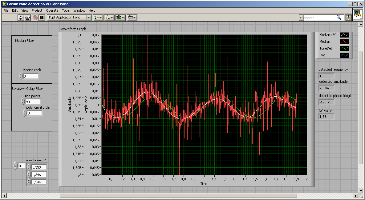
I need to extract the phase of a signal of 1.5 Hz which has little noise (see attachment files) and MAX I was recording the signal to 500 Hz. I use the filter of Labview tool value 'smoothing' with a factor equal to 3. Could someone tell me if using the right tool for what I want to do? If so, is-3 a correct number of retativaly? Looking at the result of the signal is much better.
Thank you
User
here still to play
I did not use the ordinary filter, but also more you know about the original signal, the better your filter or fitting can be.
If you know it should be a sinus (maybe even with a constant frequency) and you want the phase, go with detection of tone or a linear adjustment...
the median filter is good against the spikes, the filter of SG will make an adjustment of polynomial (original designed for adjustment of Spectra but it's also nice noise with propper settings)
Uups, the pic was taken without median filter...
If you tell us more about the signal, we could offer best filter. And keep in mind that most of the filters have an influence on the phase of the signal (late phase/group).
-
initiation of an analog signal noise
Here's the idea (the concept is available in commercial software) - to remove the background noise of an audio event, acquire a small sample pre-event, and do a FFT to discover the strength of the signal in multiple bands; It's the characterization of noise. Then set a threshold for each a little higher than the intensity of the noise signal. It is then applied to the 'event' to each frequency band - if the signal for the event does not exceed the threshold of this band, which is not part of the event, but just background noise. This I did, my question is how to better implement the filter in LabVIEW - I think both approaches, (a) filter in the frequency domain (should be easy), but can only be returned in audio in the time domain? or (b) the audio sample run through a series of band pass filter beginning by stripping the lower frequencies and working to the highest and what remains is the audio event with any other deleted. Whoever did this in LabVIEW?
Or of your approaches can be used in principle. In practice you can't get as good performance as you want.
With both methods a few time delay between the audio input and audio output will exist. How much delay you can tolerate?
(A) to two FFT. One of the pre-event segment. The other is the segment of the event. If the sgements are of different lengths, df will be different and this will make the rest of the complicated treatment. The shorter segment with zeros to fill is the easiest way to match the DSV, but will present amplitude errors. After resetting in the case where the bins below thresholds segment FFT, do the inverse FFT. Be sure to use complex numbers on all frequency domain calculations to avoid losing the key stage information.
(B) you will have to deal with transient responses and delays of the filters. Each filter with different center frequency and bandwidth will have a different response and delay. Compensate for these effects can be very inconvenient. With continuous data spikes fade, but for your process based on events, it can be a viable solution.
Lynn
-
Disabling native ring drop-down
Does anyone know how to disable the native drop-down list of controls of the ring and enum. I work (disabled) when I use the event filter and throw the mouse down event. I pop up my own fall down in a sub VI in this event and it works perfectly. However, when I try to get mouse support for this control via an event loop control, I can't throw the mouse down event because it seems to ignore all the events that are configured for this. I if a timer in case case would give me enough time to receive the event into the loop of surveillance, but unfortunately not good it (never fires). Maybe I should describe a little better:
I have two event nodes that are put in place to trigger on a mouse down event. The first is filtered to remove from the drop-down list the current LabVIEW. The second loop is top sink my code for my own downfall. This works perfectly for each type of control, I want to (string, digital) except when labVIEW runs special background code for the menu drop down. Why LabVIEW destroyed the mouse down to all the nodes in the event if only one is filtered. I can use the mouse event and it works perfectly, even if I need the mouse down to the additional functionality, I already coded and works. I have a way around this, but I WANT it to work that way for various reasons. I want no additional code in case of loop as a queue or messaging to build to handle this. It would defeat the purpose of my experience (of which I'm sorry I can't be more explicit in the details).
Why must my code be found in the events node in order to make it work? If there are two nodes of events registered for the same event, they both should receive them without worrying if one removes it by filtering. right?
Thanks in advance
Chrisco
A dark place in the LabVIEW help file:
To filter events, LabVIEW send event sequentially to each structure set up for the event event. The order in which LabVIEW sends the event filter to each structure of the event depends on the order in which you record events. Each structure the event must rule on the case of event before filter LabVIEW can prevent the next structure of the event. If a case of structure of event changes the event data, LabVIEW passes the data changed to structures of later event in the chain. If emissions of a structure of the event in the chain of the event, LabVIEW does not pass the event of any structure of event remaining in the chain. LabVIEW complete the user action that triggered the event configured only after any event structures treatment handle event without throwing.
For example, you run the vi with the filtering event loop before running that the vi with the event no filter, the filter event loop would first register (register of events using a vi containing the static events). Changing the code to save the two events as events filtering and without mods on the first lap of the event should allow you to act first and then filter then.
-
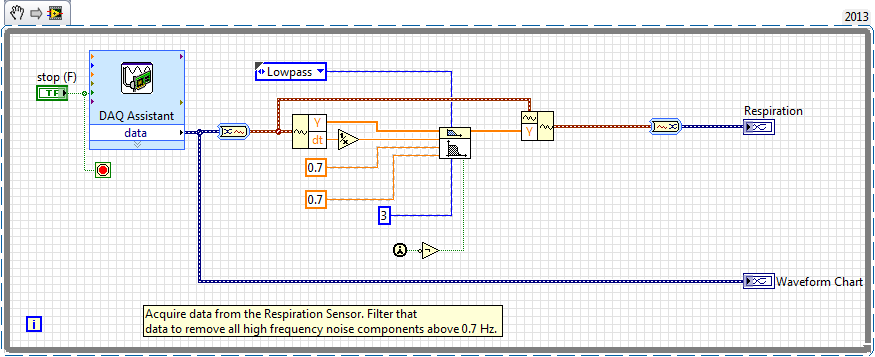
Hello! Im just a student in biomedical engineering and I need to detect the rate of breathing on labview based on accelerometer three axes, I m using the z axis accelerometer for movements of the chest and thorax breathing, but I do not see the signal of respiration. Also I use an analog butterworth filter with cutoff frequency of 1 hz (the frequency of respiration cause is between 0.1 and 0.5 hz) and a digital filter on labview. So that's my question, how can I take samples low frequencies or the signal is filtered? I am attaching the file vi that I use. Thank you!
An accelerometer is not able to travel, it measures acceleration. But I suppose the signal is oscillating so if all you want is the respiratory rate, then it will work very well. You probably need a bandpass filter with a low cutoff around 0.1 Hz frequency to eliminate any gravitational constant acceleration.
I'm not really familiar with the screw Express, but the filter there is no initialization entry, so it can be reset for each set of data that are acquired. You can use the standard filter function in the range of Signal Processing.
-
Which is the correct Point on the waveform of the Signal?
Hello
Please see attached image.
I have labview software which is to measure the load of a load cell output. According to me, that the reading is accurate, except with the software Labview, we get up to 50 lbs less when we read it with the oscilloscope technician.
What I see is that the technician measure the amplitude of the signal at the top and when there is little noise reading of the oscilloscope is even higher because the placement of the cursor is higher.
I see that LabView is more or less because when we place the cursor oscilloscope in the middle of the measurement at the center of the signal signal not top it it reads then the same my labview program. I also have a low bypass filter in labview software.
Which are the correct measure points waiting for oscilloscope to measure? in the picture as an attachment the white slider is positioned correctly, or is the correct red cursor?
It's just an example of image zoom to see better.
Thanks to you all.
JCollado
If I understand you correctly the width of the track to noculars represents 50 lbs of difference as? If you think about how works a noculars, then the center of the line displayed is probably the most accurate. The line width is determined by a few things, noise superimposed on the signal being a. So, with a noise filtering in your LabVIEW its 'width of the line"program will be closer / diluent, as it will have removed some of the noise component. Place the cursor in the middle of the path displayed in the noculars is an approximation of this, sort of looking for the point where the noise is "average" out 1/2 top / in-1/2 under the cursor, which is about the signal of 'data '. It is difficult to make measurements of accuracy of a noisy signal with a noculars for this reason, where do you put the trace? If you were to remove the filter program LP you would probably get the equivalent of the "wide trace flag" which would be a series of values that plotted close the underlying signal, but with high and low variations equivalent to the width of the track.
So after all this verbiage, I would read the trace Center, perform an average of noise 'eyeball '.
-
How about using labview vi of the filter and multiply vi to replace the analog filter and amplifier
Hi all
I use a data acquisition system to acquire a weak signal, it seems to a voltage amplifier and low-pass filter before the acquisition of data. I was wondering, if I use low-pass of the labview vi of the filter and multiply vi to process the signal picked up by DAQ, can I get the same effect as the analog low-pass filter and amp?
Thank you!
No!
1. any system of sampled data must be band including prior to sampling in order to avoid aliasing. It is impossible to remove aliasing after collection.
2. the resolution of the DAQ system will be so low that you'll very 'fat' scanning and you will lose a large part of the information in your signal.
Sorry, but you need to amplify and filter in the material before the data acquisition device for best results.
Lynn
-
Synthesis of filter multiband in LabVIEW
Hello
Y at - there some facility in LabVIEW that allows to synthesize the multiband filter, or to use another tool like Matlab.
Thanks in advance
Paavel.
What of it:
Parks-McClellan VI - 2012 aid LabVIEW - National Instruments
http://zone.NI.com/reference/en-XX/help/371361J-01/lvanls/parks_mcclellan/In addition, if you have enough resources and if your program is not the critical, you could simply put a few filters in series.
You program the FPGA? What you want to do at all?
Greetings
Brandizzl
-
If the butterworth filter available in LabVIEW FPGA is cascade, can I get a higher order filter?
I need a 10th order filter lowpass butterworth with cut-off frequency 5 kHz. Can I build by 4th cascading of 2 order butterworth filters and 1 2nd order available in LabVIEW FPGA each filter in butterworth with cut-off frequency 5 kHz?
This will increase the amount that your data will be filtered but will not increase the order in the Manor that you think. If you cascade two 2 4th order filters and compare that results to a filter of order 8, the resulting field filter cascading bode would look more like a 6,5e order filter.
Logan H
Maybe you are looking for
-
This could be the cause the dervishes ball or freezing page in Safari (most often in the Amazon)?
It is a relatively new problem. My iMac is running Yosemite 10.10.5 with Safari 9.0.3. I deleted all the data of the Safari preferences Web site, deleted history and permissions repaired without any significant improvement There is no list extension
-
Why don't the mpg2 files allow to move to different parts of the clip in XP? Vista lets me.
Hello. Why don't the mpg2 files allow to move to different parts of the clip in XP? Vista lets me. Desktop: Windows XP 32-bit Home Edition. Laptop: Windows Vista Home Premium 64-bit. I have a DVD I paid for and used a software to copy video clips (un
-
When I go into settings it greys these they are already registered. So I chose to sync all e-mail files, assuming that I could disable the files already sampled, but it only allows me to select folders additional vs uncheck the existing folders. Hel
-
Why the scheduled task cannot rename?
In Windows 7, after that I put a scheduled task, the task name cannot be renamed. Does anyone know a trick to rename rather than create a new one? Thanks in advance for your suggestions
-
Question about video conference
Hi guys I had a current situation, my client wants to videoconference thorugh Microsoft Office Communicator call, it should work between the host from one site to another, but we have already set up certain rules in the firewall, and do some testing,