Float 32 (Single) to EEPROM via I2C
I'm trying to store a 32-bit floating point (single) on 4 bytes of memory EEPROM via I2C bus. I use a parallel cable to bit-bang 8-bit ACK on the EEPROM chips.
The only way I can think to do is to split the Single in an I8 and three of U8. Is it still necessary for this or should I simply catalogued to U32 and use arrays. Of course, I'm horrible with tables, and I can't really wrap my head around how to do. Any help will be appreciated, and if I'm not very clear, I can clarify. Thanks for any help.
for example
3D23D70A-> 3D
23
D7
0A
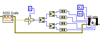
Found my solution, here it is for posterity. If anyone is ever interested can share improvements, please do.
Typecasted value of property unique to U32 node, then two levels of "Split number" function to get four U8 bytes, then fed in my custom I2C 4 bytes writing .vi.
Tags: NI Software
Similar Questions
-
Convert the hexadecimal string of Little Endian floating-point single precision
I made a lot of tinkering and research, but despite all the very similar examples, I found, I think that I am limited by my lack of knowledge in programming. I gives me values such as 0000c 641 I need to convert to
41C60000who must convert single precision IEEE754 to 24.75 as a standard 32-bit float. I saw very similar examples with boxing and unboxing conversions, but I simply can't understand it. Thank you.OK, so if you have actual letters coming, there are a few ways that you can do. You can basically change the string in order to get in order waiting for LabVIEW. Otherwise, you can do the same using data manipulation functions:

-
Receiver with built-in ARM I2C of incorrect data
Hello together
For a school project, I have to finish up next week, I need to read a RealTimeClock DS1307 via I2C.
I use a LM3S8962.
I tried to communicate via the NI USB-8451 module, which works great.
Now, I just read the data from the DS1307 and I used the built-in ARM I2C live. I get data, but the data is not correct (for example, it displays a value of 70 in the second register, which is not possible).
I tried a lot of things, but I couldn't make it work properly.
Attached a screenshot of how I implemented the reading of the I2C. What I am doing wrong? I really need to get this work otherwise I can't finish my project and this unfortunately causes a bad brand
 I hope that someone can help me.
Greetings from Switzerland
Dominic
Hi doh.
are you sure you read from the registry of law?
According to this datasheet: DS1307.pdf .
If you want to access the registry seconds we address 0 (Hex-value-0), in your screen shot his 68 decimal. You can change the representation of your constant which is connected to the terminal of the address of your create the Configuration VI reference. Just right click your constant-> visible object-> Radix. After this, you can change its representation to x (HEX).
In addition, when you read the 7 bits that are casted to unsigned 8 bit you have to notice that the 7 bits are coded as the BCD code.
So consider your example of reading the value in binary way 70: 70: 100110 with ILO the most significant on the left and the least significant bit on the right side. Now when divide you the values according to the seconds in the table of technical data sheets:
| 0 | 1 0 0 | 0 1 1 0
Then you will see, 70 as U8 has value: 0110 = 6 (last 4 bits) and 100 (average 3 bits) = 4, which means that your real value is not 70, but 46.
So I would say, you must convert the value of U8 to an array of Boolean, divide the bits according to the table mentioned in the manual and then convert them timely.
Hope this helps, if you have any other questions just after.
Kind regards
Lam
-
Hello
I am looking for a starting point.
My problem is that I have to communicate with the PCA9555 (http://focus.ti.com/lit/ds/symlink/pca9555.pdf). I searched the site of NOR and have met a USB-8451, which seems to be the answer to my problem. However, I also have to measure current and this device seems to lack this ability.
First of all, it would be the device that I would like to use to communicate via I2C? The only reason why I have a question is because I can't access the examples that would give me a good idea that I found what I was looking for.
Second, is there a device like this one offered by OR who would be able to communicate via I2C and be able to measure current? Or what I need to buy 2 separate devices?
Thirdly, is there anyone out there who has encountered the same problem (possibly with the same PCA9555)?
Thank you
Gerardo Hernandez
-
I write the values for my meter with modbus/TCP and the set point is a float on 2 registers.
Documentation, says this:
Floating point parameters are 4 bytes long and are mapped to two consecutive Modbus
registers. The floats are single precision IEEE (1 sign bit, exponent fraction of 23 bits and 8-bit) format. The
first register contains 16 32 bits, the second register contains bit 15-0.The modbus library sends unsigned words, so how I break a float in two words, corresponding to the above requirements.
Thank you!
-
writing multiple modbus registers
Hello
I am communicating to my labview program controller using modbus RTU and the controller has 16 bits in modbus registers.
To send the float as '1.23' values, I write two registers to store the hex value that number in comma floating 32 bits.
I use the modbus driver provided to this end by labview and use labview 8.2.1
I have the following doubts in this regard.
- The "Modbus master series query. VI"has the command Modbus that records an entry which I use to set the registry values in the controller unit modbus. To send the above, mentioned in floating-point registers 501 and 502 (contains the full value of the PID parameters), use the same vi, whose value should be registered first... is the high or low, to be written to 501 and 502.
- The function code to write to multiple records in the modbus driver is 16. But my document that is specific to the Controller explained in the section "writing to multiple records" with the code of function like 10. And I see that feature codes 'writing in the single register' as well as the driver for modbus producing the same type of message frame as discussed in the document. But I see no similarity in the function "write multiple registers" in the document and the modbus labview driver.
- "Even if I write records 501 and 502 one after another will use"write in the single register"function code when these registries implement floating-point single using 2 registers ' 16 - bit '. If this method is possible, then I will come and do it the same way I did it for the entry in the single register. While writing data in records one after the other with a gap between the two as small as 4 ms scriptures do good?
I suspect a confusion between 16 decimal and hexadecimal 10

Two successive registry entries are not equivalent to a double entry: during the period between the two scripts your controller will be loaded with a false parameter. It is perhaps not necessarily a source of problems. It depends on your application. Writing the MSB should first reduce the problem.
The order of Hi-Lo is dependent on the machine control. Some use the Big Endian, other Little Endian. But this choice should assign unique register values (U16) as well.
If it is not documented, you should read the records and see if the result is logical. If this is not the case, invert the byte order and verify that the problem is resolved. Good luck

Also, I assume that you know how to use the conversion feature to convert a single (32-bit float) 2 U16?
-
Hello
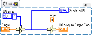
I have one to convert a float number U8 array format how to proceed?
example of 0,6 should be XX XX XX XX.
1.2 should be YY YY YY YY
size of the array must be 4 only.
I tried using the string to byte array function, but I don't know if it's good or not?
because for 1.2 I got the answer as 49 46 50 (0,1,2 bytes)
Thank you
Systemcrash wrote:
Well, if you type 0.35 as entry number type casting gives me the size of the array of 16.
I need to convert 0.35 (or any number) format of table but the table size must be only 4 & when I convert table I should come back the same number of entries.
What is the data type of your TANK? Single is 4 bytes, Double 8
I don't know where you found a table of 16 size
That's what you're trying to get a single float 32 bits?
Unique
Numbers to floating-point single precision have an IEEE 32-bit single-precision format.
Put.35 in and you obtenez.35 back
-
What is the best, pentium 3.2 GHz or Core 2 Duo
Hello. I want to play a game that requires a pentium 4 3.2 GHz or more powerful. I have an Intel (r) Core (TM) 2 Duo CPU T5550 1.83 GHz 1.83 GHz. Don't know much about computers and want to know I can play it until I open it. Thank you.
Please get/run CPU - Z and validate the exact model of your older Pentium processor
http://www.CPUID.com/softwares/CPU-z.html
In general, the Core 2 Duo will be better than the old Pentium processors even to clock speeds really low. Pass provides a list of very basic to show you the overall performance of different processors:
http://www.cpubenchmark.NET/common_cpus.html
as you can see in the graph, pass mark means that even an Intel Core2 Duo T5500 1.66 GHz outperforms an Intel Pentium D @ 3.40 GHz. It is radical enough that a Core 2 Duo is good; Unfortunately, you have to take into account the fact that Passmark is probably represents a certain part of multi-threaded performance results. Many people do not get to use all the cores of their processors multi-threaded performance is not always indicative of performance in the real world. A much more realistic (but harder to read) reference is provided by SPEC [1]:
- Goto http://www.spec.org/cgi-bin/osgresults?conf=cpu2006
- Change the drop-down list to the processor
- Type "Pentium D" in the text box of Matches
- Click on the button "run Simple extraction.
- Recording an average baseline CFP2006 results for your processor speed (assuming that you have and old Pentium D)
- Repeat 1-5 for Core 2
When I do that, I get a threaded Floating Point single rate of about 11 for a Pentium D @ 3.2 and 11 for a Core 2 Duo @ 1.86. So, if I read the SPEC benchmarks (this may be difficult), the only threaded execution of a Pentium D @ 3.2 is about the same as a Core 2 Duo @ 1.86. So I guess it's a draw one way or the other, but many games these days become multi-threaded, another factor may be the measure of CFP2006 rate which is (multi-threaded). When I do that, I get a multithreaded Point rates covered with approximately 18.9 for a Pentium D @ 3.2 and 19.6 for a Core 2 Duo @ 1.86. So the Core 2 duo wins by a small margin.
To make a long story short, I guess as a Pentium D @3.2 and Core 2 Duo @ 1.86 are substantially the same, but I guess your old Pentium is a Pentium d this could be a Pentium oldest as a single core Pentium or old hyper threaded Pentium (hack), so that the Core 2 Duo could give you gains of performance still more. In addition, Core 2 Duo will expected to run more cold than the old Pentium so school if you're a serious games, you might want to consider to make a Core 2 Duo, just so you won't have to worry about your thermal alarm is going so.
Finally, you can get better answers post this kind of question to Tom's Hardware:
These guys really take benchmarking seriously! ...
[1] - for games, you often care about decimal floating results unless you have a graphics processor really killer/physical and that you only use your main processor for Artificial Intelligence.
-
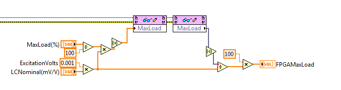
Comparison of matrix FPGA by element wierdness
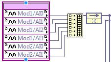
I have an application where I am comparing limits to the input values of two strain (OR-9237) inside an FPGA cards making a conditioning of signals for a subsystem in a larger machine.
Process boundaries are sent to RT as a table and compared to a table of "raw" data entry
Data entry-
Comparison of limit-
I do one per element to the "GOLDEN table" and I realize that this may or may not be more effiecient as a comparison aggregates; However, the strange thing that happens is that the sixth element of the array to limit triggers a "load error" for the fifth element of the input array.
I send you the limit directly from the RT - PS
Note that the verified calculation by reading the value defined in the FPGA. This set and get here seem to line up. That is to say, if you set the element 3 MaxLoad % or LCNominal(mV/V), it is validated on the FPGAMaxLoad output. I wonder if this has anything to do with the implicit conversion between floating-point single point-to-point fixed?
If someone has had this experience, I would be grateful feedback on what is happening.
I really want to engage in the DMA channel as it is a very small set of six elements that one, it seems more kill to use a DMA channel just for this operation.
Thank you
Drew
-
space the binary file for reading as 0x00 0x20
Trying to read from a binary file that contains values hexa% point floating in single precision. With the help of the service binary file reading and store values in an array. The problem is that LabVIEW reads the null character (0x00) as a space (0x20) character. For example, reading in 3F800000 which is 1.0 floating-point. The output in LabVIEW reads 1.00098 (rounded by LabVIEW), or a hexadecimal value of 3F80201C. No rounded hexadecimal value must be 3F802020 for this number. Is this a known problem and are there solutions? I am attaching a jpeg file of my diagram as well as binary data. I could not download a .bin file then I saved as .txt. Thanks in advance.
-
Merging of files divided through the Unix command "split".
I created several files from a single binary file via split for transfer from Linux to Windows via the Cloud. I need to join them on Windows. Any ideas that the software to join them under Windows?
Hello
Unfortunately, there is no program or command in Windows to merge files. There could be some third party programs that will help you accomplish this task. I suggest to search for a program by using your favorite search engine and then install it and check if you're able to merge the files.
Note: This response contains a reference to third party World Wide Web site. Microsoft provides this information as a convenience to you. Microsoft does not control these sites and no has not tested any software or information found on these sites; Therefore, Microsoft cannot make any approach to quality, security or the ability of a software or information that are there. There are the dangers inherent in the use of any software found on the Internet, and Microsoft cautions you to make sure that you completely understand the risk before retrieving any software from the Internet.
-
According to the information at the bottom of the WAP54G Setup screen, it can connect to the WRT54G without an another WAP54G. I want to do is use the WAP54G as a bridge to connect my DVD player with Ethernet connection to the internet via the WRT54G. Both units have the latest firmware updates. When I put in place because I think it should be the WAP54G has all the lights, but the DVD Player cannot connect to the internet. What is the possible cause.
Nothing beats a "client access point". I wrote that you must configure it as a 'Client AP'. It's what you want. And it is the label for the option that is available on a WAP54Gv3 with firmware v3.01 according to UI demo. "Client of the AP" mode, it connects to a point of access as a customer and allows a single cable to via the wireless connection.
A bridge is more complex because it connects two wired segments, i.e. multiple devices on each side.
I've written before that it does not work with a WRT54G.
There is a support web site with download support for your device, including guides and tools.
-
Resolution max HP 8560w - external monitors?
I bought recently an Asus 27 "monitor capable of resolution 2560 x 1440. My laptop could not go higher than 1920 x 1200, so I'm now looking for a replacement laptop. Will be 8560w or other EliteBook with connectors port screen do the work?
Hello
HP 8560w is a portable class workstation, it supports several external resolutions depending on the port. The list:
Up to 32 bits per pixel color depth
DisplayPort supports resolutions up to 2560 x 1600, depth of 30 bit to 60 Hz and full HD (1920 x 1080) color monitors, 24 - bit 120 Hz color depth
VGA port allows resolutions up to 2048 x 1536 at 75 Hz and below 100 Hz resolutions
Video signal DVI - D (single link) available via the DVI port optionally HP
Docking Station (sold separately) supports resolutions up to 1600 x 1200 full time or reduced from 1920 x 1200 to reduced to shutter and shutterKind regards.
-
Quickly move the maximized window from one monitor to another
With Vista, is it possible to move a maximized window from one monitor to the other with a single click or via a keyboard shortcut (instead of having to UN-maximize, drag and re - optimize)? I can't download and install 3rd party applications to achieve.
Hello j8mcmurtrey,
I was unable to find a shortcut to perform the action you want. However, you can have a look through the available shortcuts that you is provided through Windows Vista here.
Hope this helps
Chris.H
Microsoft Answers Support Engineer
Visit our Microsoft answers feedback Forum and let us know what you think. -
So, I am looking to add one of my spare 5510 firewall to my secondary network as a vpn connection.
All I want this new ASA to do is handle my site anyconnect VPN connections. I'm pretty new to ASAs if any help would be great. I know how to create a new access VPN on my ASA and I added a NAT for my inside and outside traffic to my new Pool of IP VPN.
My question is, since it's only for the VPN and I want all my current internal traffic to continue to the asa 5510 existing routing, do I have to enter the ACL to my new single AAS of VPN? ACLs are used for VPN traffic and do I need them to traffic the route via VPN?
I'll put up inside interface of connection to one of my main Cisco switches and the outside interface connects to my DMZ switch on the new ASA only VPN.
Thank you
I don't know if I am how you connect to the external interface of single ASA VPN. Normally, in this type of installation, we would see the ASA VPN "in parallel" with the perimeter firewall.
You mention the DMZ switch that threw me a little. If you are in France through your main firewall and go to single ASA VPN via the DMZ then Yes you will need to allow several open ports (protocol 50, udp/500, tcp/443 among others) and may have to do some other techniques (NAT - T, etc.) depending on the type of remote you are implementing. That's why we rarely see this configuration used - it adds a good dose of complexity without significant benefit.
When the old facility is used, you need to switch internal to know to route traffic to the pool VPN through the only ASA VPN inside the interface. A static route is more often used, although you can use OSPF or EIGRP if you wanted to.
Should generally not be any access list that VPN traffic around the Bank access lists incoming interface. Back to remote clients traffic is coming from inside and out through (and is usually part of anestablished connection) so no access list is necessary inside.

Maybe you are looking for
-
I need help on my macbook pro i5 13inch mid 2012 model when I open all black screen
I stopped just my macbook pro, when I open all the black screen but it has power... can I bring it to apple store to fix. How will they charge?
-
When you enter an address in the address bar that represents a place of slow loading (or even a site that does not exist) and then immediately after hitting enter change address link to a site that loads faster you will reach the last registration si
-
I have an infinite loop is and display of data. How can I end the loop with a button or a keypress?
-
Well, it says to reinstall Windows XP. It was running real slow, sometimes does not connect to the internet. so I reinstalled. He said the same thing and now my anti-virus, and fire fox does not work well. Can you help me?
-
Physical size and the type of disk hard drive in my XPS M1210?
Hi, for the first time poster here. I'm about to buy a new hard drive to replace the original one in my XPS M1210. I just need to know the physical size (3.5 "? 2.5"? etc) and type (7200 rpm or something else?) of him so I don't know the correct type