[FPGA] - NI 9401 - entry & exit issues
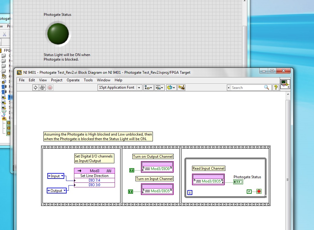
I'm trying to put my input and output on digital modules NI 9401 channels on my compact RIO to power a photogate and read the entry in the module. However, my FPGA code does not work because the way I expected... as my output does not raise my 5V expected and I don't get anything in my driveway.
I have put my lines you want at the entrances and exits and have power for my photogate to my entry on DI5 and two game I should get a high through my comparsion and et0 value. It would then turn on my LED on my front.

First, you should define the directions of the line outside of the big loop, power your device with your NOT then see if your DI rises.
Then your code seems not to be read or set all numerical values, since you use the reference stations not the terminals of the digital value.
So in fact comparison is always false (you compare two references).
Tags: NI Software
Similar Questions
-
CS6: export "range of time markers" without defining in - entry / exit point or set the work area?
Hello
in CS6, I've defined several "range of markers of time" to get a better overview of my project. Now I want to export each range in a single video.
The only way to do it is to create in - entry / exit points or the definition of the work area (which is the English translation of "Arbeitsbereichsleiste" (German),...?)?
Or is it possible to set this selection through the established range of time markers? That would be the easiest way...
Thank you, Carlos
I don't believe it. The markers are a few guides, really. They do not control a lot.
-
border drop-down color change on entry/exit event
Hello
I'm drop-down list to change the border color and thickness on entry/exit events. I found this script written by Niall O'Donovan, who works for text and numeric fields, but not for a list drop-down and chackbox.
Could someone please adjust this script for a drop down list?
Come in:
VNAME var = this.name.toString ();
xfa.resolveNode (VNAME + ".") ui.textEdit.border.edge") .stroke ="solid";
for (var i = 0; i < 4; i ++) {}
this.ui.oneOfChild.border.getElement("edge",i).color.value = "255,153,0"; orange tint
xfa.resolveNode(vName_+_".ui.textEdit.border").getElement ("edge", I) .thickness = "0,0200" in
}
output:
VNAME var = this.name.toString ();
for (var i = 0; i < 4; i ++) {}
xfa.resolveNode(vName_+_".ui.textEdit.border").getElement ("edge", I) .thickness = "0,0069" in
}
xfa.resolveNode (VNAME + ".") ui.textEdit.border.edge") .stroke is"lowered";.
Thank you
Marko
Hi Marion
The script you should to a TextField (textEdit, for example).
In the examples I give, there is a list of properties .ui that you can use for different objects:
For example:
Date field =      #dateTimeEdit
Dropdown =      #choiceList
Checkbox =      #checkButton
Text field =      #textEdit
Numeric field =     #numericEdit
If you have a look at the examples on page 2 of this example: http://assure.ly/gzOH0E.
So for the drop-down list to replace "#textEdit" by "#choiceList" AND use "#checkBox" for the checkbox.
Hope that helps,
Niall
-
FPGA NI 9401 reset high method exit glitch
Someone posted about this problem but no answer OR
http://forums.NI.com/T5/LabVIEW/FPFA-reset/m-p/2582555/highlight/true#M777501
Some electronics got fries because that when you call the reset on the FPGA method outputs go high for (way longer than they should have been...) about 100 MS
Is there a reason that the reset method on CompactRIO FPGA works this way? I have not studied how it works with other modules that the 9401.
Could this behavior if you please at least be documented in the help somewhere? It is quite important.
I finally got the hardware configuration and was able to test a 9074 9401 module. When you use the method Reset FPGA, it in effect exports 100 m we do it is documented and that KB is updated. I'll also be sure to contact the right people to see if we can get this put in 9401 help files, where it is more visible.
Thanks for that bring to our attention!
-
Playback of digital input [FPGA] - NI 9401 - questions?
I'm having some trouble with the digital input NI 9401, which is to have a uniform reading. I have a photogate that power of a digital output is turned off and goes in to a digital input module, but I can't read the entry several times. My LED flashes once and never again will blink until I restart my CRIO or recompile. I have launched the ports of entry and exit, their market and constantly for loop. Any idea what's going on?
Hi Allan,
Why you "light up" a channel of entry?
Writing a value to a DIO PIN is usually for outings!
What is connected to your PIN DIO 5? Have you checked the entry with a DMM measure?
How long the impulses are measured with this entry? Do you really you can see short pulses of light flashing?
-
Problem creating entries, exits and text in the block of Script Scilab
I recently installed the Labview with Scilab gateway. I'm under Labview 11.0 and Scilab 5.3.3. Files example executed correctly, but when I try to set entries or exits, there is no option to add ports. The block ignores also any text I type in or copy to it. I tried this on a white vi.
-
No preview entry/exit when you change the settings.
Hello
Whenever I try to change the encoding for the video options in Adobe Media Encoder, it seems that the preview window that would normally display the entry and the final exit, as well as allow me to crop images, is now empty. I tried to check the updates, reinstall media encoder and right now, get new updates from Adobe to update SOUL 5.0.1.
I use SOUL CS5 version 5.0.1.0 for Mac OS X on an iMac with an Intel Core i3, with 8 GB of RAM, processor running Mac OS X 10.7.3.
Any help is appreciated; I can provide more information if necessary.
Thank you
Noel
Apple broke this feature with Lion 10.7.3.
See this:
-
Looking for how to disable the sounds of entry/exit for large gatherings in adobe connect
Using adobe connect for ministerial meetings 'Town Hall '. Our former employee left without explaining how he had achieved the no dial tone on participant enter/exit.
Does anyone know where is this feature? I have been going through the menus and options, as well as PDF files online and cannot find this information. Really grateful for the help.When the compound as the host, the command to disable the doorbell is * 47.
Complete list of the commands of the host can be found here: http://www.meetingone.com/whitepapers/Audio_Host_Commands.pdf
-
Injection of error in error of type entry / exit system
Hi I'm just starting in Labview and to this day, I've been joining void screws with Out error connecting to error in the next sub VI so I can capture errors at the end of the line of screws that are up of my program.
It occurs to me that sometimes there are errors that occur that are not lifted by the system, but rather the dice indicate, for example, during a test product, when a test parameter is not a valid range. I wonder how to convert say a Boolean value for test pass / fail, an error with a message, that I can put in my path of the error. -What is in general?
Some setting in context, I want to be able to test the two devices manufactured in a single sequence. If we fail a test sup, say a voltage is out of range, I want to inject than as a mistake and blow it at the end of this trial where he would be treated, and perhaps a group of experts on the GUI shows then in case of FAILURE or something similar. But enforcement should then immediately move on to the second device and start this test, without waiting for an acknowledgement so that when the tester returns, both have been tested and can determine what to do with them, according to the State of SUCCESS or FAILURE.
I guess I asked how to remove a custom error and caught him? I've read a few articles about the error handling which doesn't really answer my question. Thanks for the tips!
You can use the package by name to create the cluster error yourself with a Boolean value of True for the error (false is a warning), a number (0 for no error, a positive number of alert, negative number for an error) and a string for a message.
If you must use the cluster of error in this way is a different matter. I would recommend against it. I consider the cluster of the error to be there for clerical errors and program errors. Basically if your program runs correctly and that you have no hardware problems, and then a mistake should never appear on the cluster of error. For the case where you are dealing with outages of a unit under test, pass/fail results, I consider that it is a normal part of the program, and that the data should be treated separately as part of your test data and not forced in the cluster of error data. Check the condition of the success/failure of data to determine whether to execute all Subvi who should or should not run because a previous test failed.
-
Impossible to add markers or entry/exit points in prelude - please help!
I can't add markers. my keyboard is wireless, works very well, but what happens? I get half of the use of prelude because of this.
Hello
Currently, Adobe doesn't support metadata for GoPro media. If acceptable, you can transcode your GoPro to ingest using prelude (even to h264) so you can connect it and the buttons to add markers will work. Is there something in the video headers Gopro that prevents players from our base of grateful as standard h264. We are currently reviewing it.
Hope this helps,
Michael
Sent from my iPhone
-
Cuts, deadlines and entry / exit points
You can insert points indicate available rather than by the movements of the mouse?
1. watch any clip.
2. brand and name of say 5 sections of the imported clip as suitable for the insertion of the timeline.
3. Repeat step 2 above in number of clips x.
3. insert these sections marked in the time line - but not necessarily in sequential order.3 must be done immediately after a section of step 2. Once you move to a different section in step 2, you lose the ability to do 3.
To clarify:
1. watch any clip.
2. mark a set In/Out points
3. Insert the clip.
4. repeat if necessary.
That either with the keyboard or the mouse, it can only be done in that order. As far as I know, it's endemic to the NLE.
-
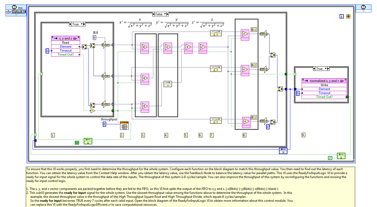
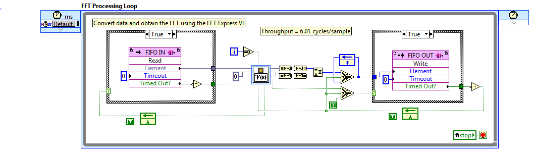
SCTL FPGA flow and ready for input management
I studied the FPGA Normalize vector LV examples and I have a question on the loan for wire entry (see the attachment for the diagram).
A Subvi (named ReadyForInputLogic) is used to generate a ready for the true input signal each 7 cycles after each valid entry.
I understand the purpose of this sub - VI but it's the Subvi can be replaced by a wire between the 'ready for the entry' exit last ditch block and case diagram where the FIFO is read?
I also studied the example of co-processing FFT and there is no need to use this kind oh Subvi:
I modified this example to add some multiply and divide blocks after the block of the FFT. Thus, the flow of any new is increased to 8 cycles/sample (the block of the FFT is not the bottleneck).
I have to add the ReadyForInputLogic.vi in my SCTL Subvi read FIFO each 8 cycles?
Thanks a lot for any explanation
Zoomzoomzoom wrote:
RUFNEK wrote:
I understand the purpose of this sub - VI but it's the Subvi can be replaced by a wire between the 'ready for the entry' exit last ditch block and case diagram where the FIFO is read?
Yes you can, but then you run the risk of dropping a result when writing to the FIFO fails, because it is full. The logic is currently configured to stop processing vectors until the FIFO is not full.
RUFNEK wrote:
I modified this example to add some multiply and divide blocks after the block of the FFT. Thus, the flow of any new is increased to 8 cycles/sample (the block of the FFT is not the bottleneck).
I have to add the ReadyForInputLogic.vi in my SCTL Subvi read FIFO each 8 cycles?
Thanks a lot for any explanation
You must add the latencies to determine how many times you can read FIFO. The FFT under Setup for this example has a latency of > 5600 cycles before the output is valid. -
Hi, I recently bought numbers in order to create a commercial newspaper. I'm the pen and paper. I need help to create a formula. A purchase column; Determines if the entry price column is subtracted from the price of output column (buy) or subtracted from (Sell) entry exit. Thank you for your help
Hi B',.
Buying and selling in column B
Price of entry in column c.
Exit in column D price
Formula (and outcome) in column E
If the column will B always contained 'Buy' or 'Sell', it works. It is default to a calculation of 'sell' if sale or has been specified.
E2: = IF (B = "Buy", D - C, C - D)
If you want to delay the calculation until the amounts entered in C and D, use this version:
E2: = IF (OR (LEN (C) < 1, LEN (D) < 1,"", IF (B = "Buy", D - C, C - D) ")
If you want to delay the calculation until all three ducks are on a line (B contains buy or sell, C and D contain both data), use this version:
E2: = IF (OR (LEN (C) < 1, LEN (D) < 1,"", IF (B = "Buy", D - C, IF(B="Sell",C-D,) "" ")))
Third version used in this table.

Kind regards
Barry
-
7953 FPGA with 6581 adapter world clock inputs
I am very new to FPGA with LabVIEW design. I have a FPGA 7953 card that connects to the 6581 adapter. This brochure, looking the 6581.
( http://www.ni.com/pdf/products/us/cat_ni6581.pdf )
on page 3, it says "Note: clock is connected to the world clock for the NI FlexRIO FPGA module entries. I think it means that DDCA, 67 of the 6581 pin, I can feed an external clock in which is accessible in my LabVIEW FPGA code to entries world clock of the 7953? I don't know what these entries world clock would be on the 7953. It would be one of the choices presented to me as shown in the attached picture?
Sorry if this question is wacky...
Hi JHaas,
I think that I can't fully responding to your question. Yes, you can introduce an external clock in the 6581, which is accessible in your FPGA code. Take a look at this knowledge base article which has some more details on the pins to use, and how to use the clock in a timed cycle loop.
-
read or write to the fpga of e/s node
I am unable to read or write to a knot of e/s FPGA. The entry is grayed out.
The DIO module channels started writing? You need to go into the properties of the module and select this option. Find the module in the project, right click and choose Properties. I don't know which module you have, but if it's 8 channels, you can usually do it in groups so that you can put channels 0-3 to read or write and channels 4-7 to read or write. But you will not be able to each channel individually have it's own settings, cordially. But it may be different on certain modules.
I suggest you look at the settings.

Maybe you are looking for
-
Run Firefox 30.0. Everything is OK. It stop at the restart of Mac to install the Mavericks 10.9.4. When it reopened most of my favorites had disappeared from their records. In addition, many cases are now designated, "Unsorted Bookmarks." They are to
-
ProBook 430 G2 - left trackpad button does not respond intermittently
I have a brand new ProBook. G2 430 (SKU # G6W35EA #ABB) with Windows 8.1, completely up to date. I find that every 10-15 minutes, the left button on the trackpad becomes unresponsive. The trackpad still moving the mouse pointer and the right button w
-
Recently, I had a hard drive crash and had to install a new hard drive. When I did I perform a clean installation of Windows Pro 10 on my system now I'm having a few problems with some of the items from my original installation. I no longer seem to
-
Compaq Presario CQ5305UK NETWORK ADAPTER
I moved my Compaq Presario CQ5305UK in another room and attempted to install a new Belkin AC USB Network Adapter so that I could connect with my router wireless broadband. It did not work that I could not connect my PC to my broadband router wireless
-
Missing or damaged cartridge on Photosmart C309g
The printer display indicates that a certain cartridge is missing or damaged, but if I remove another cartridge, the first cartridge is accepted and the other cartridge is missing. I replaced all cartridges and was able to print test pages, then I go