generate pay cycles
Hello
Beginning of the year on the payroll in the month of October and ends in September. management will pay wages to employees two weeks once (on Friday).
For example, for 2014, pay start date October 10, 2014 (second Friday of the Oct 14) and the end date are 30-Sep-2015.
Cycles of payroll for the last month should be 11-Sep-2015, 25-Sep-2015 to 30-Sep-2015
under query will generate cycles of pay up to 25-Sep-2015. (1) how to get 30-Sep-2015 with the Sub result.
Select to_date ((next_day (next_day (to_date (1er octobre 2014 "," Lun-jj-aaaa '), 'ven'), 'ven')))
+ ((level-1) * 14), 'Dd-mon-yy') pay_date
of the double
where to_date ((next_day (next_day (to_date (1er octobre 2014 "," Lun-jj-aaaa '), 'ven'), 'ven')))
+ ((level-1) * 14), 'Dd-mon-yy') < = to_date (30-sep-2015 "," dd-mon-yy')
connect by level < = 30;
PAY_DATE
--------
10/10/2014
24/10/2014
07/11/2014
21/11/2014
05/12/2014
19/12/2014
02/01/2015
16/01/2015
30/01/2015
13/02/2015
27/02/2015
13/03/2015
27/03/2015
04/10/2015
24/04/2015
08/05/2015
22/05/2015
05/06/2015
19/06/2015
03/07/2015
17/07/2015
07/31/2015
14/08/2015
28/08/2015
11/09/2015
25/09/2015
Thank you
Suri
How about simply adding (as a constant) to the result set via the UNION?
Tags: Database
Similar Questions
-
Calendar synchronized with Diuble pulse using PCI-6601
Hello
I'm trying to run a PIV of Labview 8.5.1 system using a PCI-6601 map at the exit of the signals for the laser and the camera.
This requires a line for the camera, one for the FPS (first removal of pulse) and one for the Q-switch.
The difficulty is in the need of a double pulse on the Q-switch for mode double frame PIV.
The distribution box that I use is not one NOR one and I don't have access to 3 outputs four against, otherwise, quite simply, I would use a BNC t with two pulses slightly staggered junction.
I have access to a BNC-2110 timing box, but I think it is not compatible with the PCI-6601 and have no funds to buy a BNC-2121 right now.
I managed to create a double pulse by using one of the counters with a finite number of impulses set to 2 and then stop the task, then run this in a timed loop.
However, it is then based on the software, which is not precise enough for the application, and I can't figure out how to get the timed loop to run from the time of 20 MHz of 6601 map base.
I could be missing something obvious here, or perhaps is more annoying? I'm fairly new to DAQmx.
Thanks in advance
Joe
Dominic makes a good point about the operating system, but really the best solution is to use the hardware timing when possible.
I have set up an example that shows how you can implement different sets of impulses finished using the calendar of the Commission. It requires the use of two meters, but then again a generation of impulses finished the fact (on the 6601).
Communities: Generate several Cycles pulse finished using two countersAlternatively, if you have another signal that you want to use to trigger each set of pulses (rather than to specify a rate so that they occur as in the example above), counters on a 6601 are redeclenchables then you can use the external signal to trigger the generation over time and time again without having to stop the task in the software.
Best regards
John
-
Dear Dina,
Is this logic? getting module AP Planner? What sense? Wat type of interaction? all standard reports to keep track of purchases to pay cycle(in the)
dimension of the projects)?
Please, help me to understand...
Thanks a lot n advanceHello
When you enter invoices from suppliers in the AP and fill in th eproject distribution, this Bill is eligible as costs of the project.
Run the process Interface Provider costs of projects and each project associated with online distribution will be imported as an item of expenditure in PAYou can consult the Oracle project costing guide. Chapter 7, you can read the article - integration with purchase of the Oracle and Oracle accounts payable (requisitions, good order and vendor invoices).
Dina
-
How to generate two pulses per cycle? PCI-6251/6255
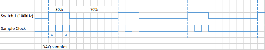
Hello. I want to generate two or more pulses per cycle like the timming diagram. This pulse will be used to trigger the sampling data.
I am ussing the PCI-6251. The VI examples to counter outputs can easily generate the first line, but the second I have no idea. All information can help.
Another problem could be the synchronization of this lines and data acquisition.
Concerning
Ivan C.
I would like to use the digital outputs for this - just generate a continuous at 1 MHz clock using one of the counters and write the following in your digital output lines:
H H H L L L L L L L
H L H L L L L L L L
If you want to use these signals to pick a different spot on the 625 x, you the output of wire in a PFI lines.
Best regards
-
How to generate the digital output of the variable duty cycle and clock source being contrary?
I want to generate a digital pulse every front amount of my pulse counters. He must have a variable duty cycle. until now, I've been able to generate a digital output, but I can't change its duty cycle.
pls tell how I should proceed?
Thank you in advance...
-
How to stop up to generate a waveform of the entire cycle when click on the stop button
Dear engineer OR,.
I have generated three AO signals to control my scanner and data acquisition. Two ramp signals is to control the galvanometric scanner (x and y). A TTL signal is to trigger the acquisition of data. Whenever I click on stop, the ramp stops every time that it is when the button is clicked, what causes a voltage jump when will resume the program again because the ramp will start in the place original (this jump of fast voltage can damage the galvanometric scanner). Could you please give me some suggestions on how to stop after only a waveform of cycle whol's over? The VI I used is attached. The FLIM control.vi is the main vi include Subvi Galvo control.vi
Thank you very much!!
Hello, dgql!
From a point of view purely programming, there are a few ways you could implement this.
(1) create a conditional stay:
You can add features to the code such that, once you reach the stop button, the code checks the value of your signal before you actually stop the VI. In pseudo-code: "If the signal is > 0 and less than a certain value, stop." Otherwise, keep the control of signal until the value lies in this range. »
(2) to reset the signal from the ramp at each start of your VI. This may or may not work with your application, depending on whether you must have the previous value of the ramp carried over.
Let me know if these are of no help!
-
How to use NI9474 and cdaq9172 to generate the right variable cycle pulse 1 kHz
Hello, I would like to use a NI9474 (in a cdaq9172 chassis) to send a square with a frequency of 1 kHz wave. The cycle will change just about every second (based on NI9205 voltage readings in all separate loop, by controlling the local variable 'duty'). It is important to have a temporal resolution of decent output; that is the difference between 50% and 51% of duty cycle must be determined. 9474 says that it has a speed of 1, so I expect that this is possible. This is used for a buck converter. The output is switching on and off a MOSFET, which only needs 5 volts, and less than a mA, when on. I tried a "simulate" with a square wave signal using a frequency of 1 kHz and 100kS/s and introduced in a DAQ assist with dynamic data to the converter Boolean between (probably not the best approach I admit). I tried also implemented using the DAQmx screw (without help). In both cases, I got an error that says that I need an external clock. I know that the chassis has an internal counter. This could be used for synchronization? I looked at examples of Pulse counter, but which seems to be to use a meter as output, not a digital channel, so I'm a little confused. The numeric examples do not seem to be what I want either. If I can't use the chassis for synchronization, it is possible, that I could get a NI9401. Could I use this counting or establishment of a clock (I could attach a function generator using a square wave of 1 Mhz for example)? For example with a 1 Mhz clock, then for a 50% duty cycle signal 1 kHz, after 500 clocks range from low to high and high to low after the other 500, (or 510 and 490 in 51% duty). Is something like that possible? Thanks for any advice, Thomas I should confess do not understand the things of meter too well at this point. Many of the examples I've seen, are apparently complicated screws.
Hi Thomas,
You can certainly do with a counter pulse train generation by using your 9474 in a cDAQ-9172 chassis. Make sure that the module is in the slot 5 or 6 (latest chassis do not have this restriction). Examples of pulse train located in the finder example under entry and exit-> DAQmx hardware-> generating digital impulses. The example of Gen dig Pulse Train - Continuous.vi is probably in the neighborhood of what you want.
To update the market on the fly factor, write the Co.Pulse.DutyCyc channel property after the task starts.
-
bug cycle generating function to have to
Hello!
I put the function generator at 1 kHz, 25% from the simulation, its ok, but when I click on the arrow pointing upwards on the cycle to increase one percent, the output of the unit is now 100-26 = 74%. And therefore, work is reversed. (see: 11.0.278)
Hello
I just learn from our developers. The issue has been reproduced and entered into their system with the ID report bug: 117065. The fix will be included in one of future versions. There is no direct workaround solution. If you have an educational version of Multisim, you can use the input of the generator with NOR-ELVISmx drivers - this one works very well. Please let me know if there is anything else I can help you.
-
Extraction of Cycle Count of the system report
I have an action automator, put in place to generate a report of power system and create a file of text based on it. Is there a way I can extract the Cycle of this number?
From the Terminal:
$ system_profiler SPPowerDataType | AWK ' / Cycle Count / {print $3}'
Back: 96 (on my MacBook Air of 2014)
-
am adding memory when I remove the battery I have to pay in order to get the full charge of her
am adding memory when I remove the battery I have to pay in order to get the full charge of her
N ° but see:
About the batteries in the modern Apple laptops
Extending the life of your laptop battery
Apple laptops-calibrate the battery in your computer for optimal performance
-
I want to buy a family music iTunes subscription share with my brothers and sisters. I was wondering if we could so and yet they each be responsible for their own purchases. I want to share a music subscription, but I don't want to pay for their app, music purchases purchases or any apple purchases also. Is this possible or am I dreaming?
Hi TMill41,
Welcome to the communities of Apple Support! If it is possible for individual members of a group sharing of the family to pay for their purchases via gift cards or credits, all costs beyond that will be automatically charged to the organiser credit card by design, as shown in this article:
Make purchases
After you set up your family, anytime a family member throws a new purchase, that it will be charged directly to your account, unless the family member has gift or store credit. First of all, their store credit will be used to pay the invoice total or partial. The rest will be billed to the card of the family of the Organizer. The family Organizer, the revenue generated by the transaction will be sent to you. Learn more about how are charged purchases made on iTunes Store.
Purchases and payments - Apple Support families
Concerning
-
Jitter in response to signal generator of digital dashboard by using trigger nor tclk with digitizer
I've written a VI that uses NEITHER tclk to synchronize a generator (PXI-5422 named FGEN1) and a digitizer (PXI-5122 named DIGITIZER1). There is also a clock card TIMING3 generating a digital camera.
It seems that can probably be explained by the way TCLK to synchronize, but I don't understand all the details. Could someone help explain this to me?
You are right. NOR-TClk ensures that all synchronized devices start at almost at the same time, to the same sample clock, with timing very tight. Sometimes, the level of synchronization with the devices OR TClk-synchronized beats at the level of the synchronization of the instruments of some competitor channels in the same device. But this is not free, there are compromises and added additional jitter for trigger response time is one of them. Here is an attempt to explain why:
When you use NEITHER-TClk and send a trigger, the devices will respond to relax on the next cycle of the clock once made the trigger signal to the device. Let's say you have several devices all of them even configured with the same clock frequency. You block the signal of PXI_Clk10 using their PLL, so they drift out. But each unit's clock edge will be off, clock +-0.5 cycles. If you send a trigger to each of them, they will respond on the next clock cycle whenever it is, after the arrival of the relaxation to each device with different propagation times, whatever they may be. You get a single clock cycle of jitter on reaction of device to set it off.
When you use NEITHER-TClk, several things happen: all devices are locked on the PXI_Clk10 signal to eliminate drift. The device clocks are then adjusted to a period level secondary clock. Very very tight. Then a clock signal common, slower called TClk is produced inside the devices. All the generation of trigger are delayed to be sent to the next rising edge TClk, and all consumption trigger is delayed to be received at the next front descending TClk. This way you make sure that propagation delays don't mean one of the devices does not react to the trigger until the next clock cycle.
That's why you see jitter above the reaction time of relaxation. When you add devices with different clock settings, so the frequency of the TClk can be slower for a divisible frequency in the device clock frequencies everything is possible. This causes the trigger jitter of reaction time be even slower!
I hope this helps you understand what you see.
-
generate the output waveform on 6259
Hello
I would like to generate signals of "simple" digital square output 3 6259 NI Board of Directors of 80 Hz.
Because of the wiring of my test tool driven 6259 Board, I can't use the output of the meter, but I need to plug into 3 output lines.
I re-used an existing vi and made by a subcontractor, but the generated waveform on my DUT does not have the expected frequencies (although it seems OK on the generated graph). Indeed, there are some forms of square waves, but not continuously. A sort of "pomade" and "elected" frequency does not match the measured frequency. If someone has an idea to help me, I have not experience on labview yet!
Thank you!
You have 4 unique digital States aimed at bike. Each cycle produces 1 full period of each of your square waves. If you want the output to 80 Hz, you must set the sample to run 4 * 80 = 320 Hz clock.
The other thing you see on the scope is that there are short bursts of pulses with parent long time between bursts. The calendar during the bursts are what control tasks. The time between bursts is caused by using the button "run continuously. Also that according to them, you complete vi almost immediately rather than waiting until they run awhile. Put an end to the execution of vi initiates self-cleaning of LabVIEW. These things represent the time brief burst and the ISH between bursts.
-Kevin P
-
Agilent 33500 B configuration of duty cycle
I use the function generator to Agilent/Keysigt 33511 B to produce a square wave with offset, amplitude and frequency specified. However, I'm unable to set the duty cycle. Is there a VI to control this setting?
Hi jmountney
If you use this driver , I think that there is a function named .vi configures signals Standard Advanced (square) and it has an entry for the duty Cycle, so I think this could help you.
-
Hello
I'm reading pulses TTL of a generator of service using a meter. I apply a 1 kHz signal to the meter. Each time counter reads the pulses correctly in the first cycle of measure, but it lacks some counts in all subsequent cycles.
I use NEITHER 9181 cDAQ chassis and NI 9402 module with 2014 LabVIEW and NI Max 14.0.
My computer has the Windows 8.1 operating system.
Please find the VI joint and the front image after EXECUTION.
I also used the same VI with chassis USB cDAQ-9171 . Results have been improved, but the same problem persists.
What could be the reason for this, please guide.
Thank you!
B. Sharma
1. the loop time is defined by software and therefore won't be compatible.
2. you restart the meter patch between each iteration of loop - so that the task is restarted, it does not take samples. The new start is faster on the USB device from the device ethernet due to the latency of the lower bus, so that explains why the behavior is improved on the 9171 compared to the 9181.
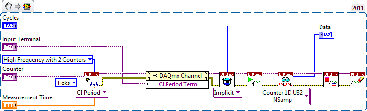
Using method 2 meter would be a clever way (maybe too smart...) to implement which, according to me, you are looking:
This will configure a second counter (ctr0 is paired with ctr1, ctr2 is paried with ctr3) to generate a signal of a period known (time measurement). The meter is taken into account the number of external pulses during this period, and since we are because data in terms of 'Ticks', it will give you the number that occurred during the measurement time. This measure is repeated for the specified number of Cycles without software-timing or latency between cycles.
The appeal of reading will have a time-out value long enough to ensure that all cycles have completed (or you can query to see if the task is made first of all to give the user the option to cancel the measure).
Best regards
Maybe you are looking for
-
When the update of Mozilla to 18.0 the drop-down list of my client site stop working
My client's Web site is http://arivins.com/.When the update of Mozilla to 18.0 the drop down menu the menu (main menu) stop working.The site is based on Joomla 1.5.26.I try to update for Mozilla 19.0 but still does not work.Please help me solve this
-
USB, dead after install XP Professional on 1850-S801 - HELP!
When I got the laptop XP Home edition has been installed. Windows XP Professional is installed and in the Device Manager I detected USB devices. But any device I plug in USB, not a single device is detected and I get no response at all the USB ports.
-
API calculation time expired or recording clock ticks
Is there an API available in LabWindows to memorize the graduations or calculating time expired? It is necessary to use with a do while loop. I want to perform an action repeatedly to 260milliseconds in a while loop and then get out of the while loop
-
I'm having a problem with the 6 blind window. I can not even find this program on my computer. How to spend it?
-
Pavilion g7-1368dx upgrade to A8 - 3500M, does not start
My Pavilion g7-1368dx came with a processor A6 - 3420M. I have the BIOS f.52 (works very well for months). I tried to upgrade the processor to an A8 - 3500M (same 35W TDP, socket FS1, and turbo 1.5GHz/2.4GHz) for a boost of graphics (400 vs 320 sha