Generating Train.vi impulses
Hello
I use the PCI6023E card and I want to generate a pulse train ended up on one of the counters. In my simple program, I don't have the Train.vi pulse generate with the following input parameters.
Device number = 1
Meter number = 0
OK, I need connect the 1 meter out put at the door of the meter... Solved.
Tags: NI Software
Similar Questions
-
Hello!
My problem appeared when I tried to update my traditional NOR-DAQ legacy code to DAQmx.
I use 2 meter (meter 5 and 7 meter) on PCI-6602, to generate trains of pulses, as well as the lines of e/s digital port 0 (the form lines from 0 to 7). What I do in my request, it's that I'm starting to generate the pulse train on the output of 2 meters and after that I play with the State of digital lines.
Traditional, it was no problem to use the meters and digital lines at the same time, everything went perfectly, but in DAQmx, is not possible.
What's happening: I start generating train of pulses on the output of counters, no errors, but when I try to change the State of a line of digital port the generation of the pulse train is stopped. What happens when I start the task associated with the digital way.
My question is: is it possible to create a channel on digital lines without changing the channels created for meters?
Another thing that I managed to do with the panels 'Measurement and Automation Explorer' and Test for PCI-6602, is basically the same thing, I generate trains of pulses on the output of the 7 meter and try to start a job on the digital line, but I get an error:
"Error-200022 occurred in test Panel.
Possible reasons:
Measurements: Resource requested by this task has already been reserved by another task.
Device: Dev4
"Terminal: PFI8.On the contrary if I use the counter 0 or a counter 1 to generate trains of pulses I encounter the same problem.
What resources are used by 2 to 7 of the PCI-6602 card counters and the counters to 0 and 1 do not use?
Thanks in advance for any answer!
Ciprian
After doing some real tests on this device, I found that it is a normal behavior for the jury of 6602. This is because when you start a task digital all 32 lines are configured for digital i/o, so it replaces your meter operation. The article below the link explains a little more on this subject. You must start the digital task before the task of counter to use the features of both in your program.
2 meter and above will not work correctly when you perform digital i/o on NI 6601 or 6602
http://digital.NI.com/public.nsf/allkb/43F71527765EEC3886256E93006CD00C?OpenDocument
-
generate trains of pulses of 5 kHz
Hello
I would like to generate digital impulses to 5 kHz oe less rate, any recommendation of material? better usb and budget type.
I have usb 6501, I try to work on this, maximum output is 1 kHz the best. Is it possible to above?
Appreciate any help here.
Kind regards
Simon
You can use each channel to generate the train of pulses at a different frequency at the same time, and generation of pulse stops immediately as soon as the task is stopped.
-
Generate trains of pulses overlap several
I need to generate signals up to 8 TTL pulse, train up to 500 Hz with heavy duty from 0 to 100% open and close the valves with an accuracy of timing of 5 microseconds. The pulse trains will be spread with equal delays and begin with a single trigger.
i.e.: If you have a period of 40ms and 8 valves, there will be a 5ms delay between each pulse train early. Each will have the same duty cycle and the period.
Trains of pulses must be performed simultaneously and stop when certain data criteria is met (the balance of the system state).
My Questions:
1 would be classified these as continuous or finite pulse trains?
2 do I need to use a counter/timer (or 2) for each train of pulses or can it be coupled with digital output?
3. what DAQ will have sufficient resources (counters/timers, DIO, etc.) to enable this work?
Thank you
1 continues. The idea of pulse trains finished is to predefine * precisely * how many cycles to generate. You will make assessments based on the software to decide whether to stop the pulse trains, but you will not be able to predict when this will happen in advance.
2. all things being equal (and it's not often), I could certainly do that with counters. You can easily reach the accuracy of your calendar and let the data acq hw do all the work. DIO can be an option, but it could prove to be a pain in the neck to set the output buffer to handle delays including and precision, you need.
3. I'd go with an oldie but goodie, the PCI-6602. It has 8 available counters, as well as a little extra DIO.
-Kevin P
-
How to connect USB 6259 so that I can generate trains of pulses of a meter
Hello
We just bought NI USB-6259 BNC. We used to use BNC-2110, which integrates the connectors BNC for trigger and the meter so that we can send trains of pulses through it to our electric Stimulator.
However, I find no terminal BNC for the output of the meter on the new device. Could someone teach me how do?
Thank you
Jay
Hi, Jay.
Big question. The screenshot below will give you the Signal of Counter/Timer associated with its respective PFI line:
This table is located in the NOR-DAQmx help (using terminals of NOR-DAQmx devices"OR USB - 6259 BNC).
To access these lines PFI one of the BNC (User 1 and User 2) user-defined, the line due to PFI line of the user desired. For example, if I wanted to access counter 0 Out of 1 BNC user, I would wire pin 1 USER on pin 12 of PFI. Manual specifications USB-6259 BNC does not give a good description of how to access the user 1 and user 2 BNC, so I refer to page 9 of the Manual of the BNC-2110. It's the same idea, just different pinout.
Let me know if you need more information. I hope that you are having an amazing day!
-
I have a generator of two impulses. I need to write to a file the three intervals Ao0
I have a two train pulses a 6009. They are Ao0 Ao1. Ao0 output will produce the total time on my meter. The façade shows 3,1,3. I can run the relay very well. I need to write about my 'Write to file - LVM' the same 3 intervals in time. Write after 3 seconds, the overall data. After 1 second, then after 3 seconds more.
Thank you
Philippe
wrong file
-
FPGA to generate the counter and pulse train
Hello
I have some experience with Quartus, but new on the FPGA OR.
I have a PCI-7811R. I'm trying to use it to illuminate sequentially 144 LEDs repeatedly. The duration of each pulse is 480us.
Basically, I need to generate a pulse and generator of a counter to record the number of pulses and, according to this number, select which light is lit.
I designed a pulse generator train based on an example of using FPGAS and added a counter in it. You can see in the attached vi.
My question is,
When I put the I/O node inside loops call single cycle, it can generate the correct pulse. However, when I tried to use the local variable to transfer data from the SCTL and then plug it on another node of I/O, I can't detect the pulse signal when I measured this I/O.
Is there something wrong with my code when I try to transfer the data of the SCTL? Can I also use local variable to transfer the value of counter, because I will need it in the next part.
Thank you!
If you are referring to the wired local variable to DIO2 in your attached VI, the problem is very simple: it is outside a loop, then it executes only once. Put this local variable and the node of IO in a loop and I think you'll get something close to the impulse you expect (although if it is not in a loop of single cycle you will have exactly the same calendar).
-
Generate impulses to drive an instrument AND trigger some HAVE (the S Series DAQ)?
Hello
I use a PCI-6122 (with LV 7.1 and Windows XP). I'm generating a TTL pulse with one of the counters on the Board (from 0). I need to use this momentum to drive a shutter and also as a trigger for data acquisition (HAVE). Is there a way to "split" the output so I can receive TTL pulses to two simultaneous different terminals, for example to "CTR OUT 0 ' and"PFI 3"? If not, could you please explain to me, or direct me to the equipment, on the if (and how) I can synchronize the two counters in order to achieve the same thing?
Thank you.
Never mind... I figured out how to generate both synchronous impulses go both counters using a common trigger: I use a pulse generated from a digital lines (DO) that I'm physically routing to the CTR terminals 0 DOOR, i.e. PFI 9 and CTR 1 DOOR, i.e. PFI 4,. I am attaching a capture in case it is a help to someone on the other screen.
-
Pulse train generation question-PCIe-6320
Hi all...
IM using PCIe-6320 series daq x to generate trains of pulses. I went through the examples found in the labview to generate digital impulses. Provided vi runs without error, but I could not find any pulse output in my PIN ctr0. Is there a specific connection to check the output?
Hello..
I had a problem with the interface cable, I found this later.thanks.now I havesolved.
-
several finite pulse trains of TTL
Dear members of the forum OR,.
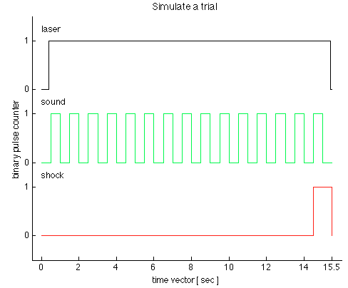
We have just received a chassis NI SMU-1073 with an SMU-6361 OR switched in PXI1Slot2 and a shielded connector BNC-2111. Aims to generate trains of three TTL pulses to control a laser, sound and shock via Matlab Application. I use the C OR-DAQmx API with Matlab MEX to integrate C in Matlab code.
I came up with the following code in the examples in C to generate a pulse over TTL time-based train:
initialDelay float64;
float64 lowTime;
float64 highTime;
uInt64 periodsPerTrain;
float64 taskMaxTime = (lowTime + highTime) * periodsPerTrain + 2 * initialDelay;Configure Pulse
DAQmxErrChk (DAQmxCreateTask ("", & taskHandle));
DAQmxErrChk (DAQmxCreateCOPulseChanTime (taskHandle, "PXI1Slot2/ctr0","", DAQmx_Val_Seconds, DAQmx_Val_Low, initialDelay, lowTime, highTime));Configure the Pulse Train
DAQmxErrChk (DAQmxCfgImplicitTiming (taskHandle, DAQmx_Val_FiniteSamps, periodsPerTrain));Departure Train
DAQmxErrChk (DAQmxStartTask (taskHandle));Wait for execution
DAQmxErrChk (DAQmxWaitUntilTaskDone (taskHandle, taskMaxTime));Clean
DAQmxStopTask (taskHandle);
DAQmxClearTask (taskHandle);I'm stuck with two problems:
1.) SMU-6361 has 4 meter signals ctr0-3. With the above code, I can generate separate tasks for each TTL signal and evoke them consecutively with DAQmxStartTask. But in this case, I guess that the tasks are not synchronized. Can I use the clock signal to synchronize the other 3, for the tasks of each is triggered at the same time? What will be the right way to do this with the C API? The step of the smallest of the discrete-time in the example is 500ms. see the picture as an attachment to check how the TTL signals should look like.
(2.) what is my physical connector on the BNC2111 to outsource these signals.
/ PXI1Slot2 / ctr0-> PFI12/P2.4
/ PXI1Slot2 / ctr1-> PFI13/P1.0
But what ctr2 and ctr3? How can I configure the physical connector outsource? Is there a function to specify that?
Thank you in advance for any advice, suggestions and directions!
see you soon,
go9kata
Hello go9kata,
for your second question, with the BNC-2111. You can route the signal from the counter for
lines PFI avialable on the block of connection BNC 2111 with the following syntax
DAQmxErrChk (DAQmxSetCOPulseTerm(taskHandle,"/Dev1/PFI0"));
I hope that helps, if not please let me know.
-
HOWTO generate a pulse for each Image Grabed?
Hello
I use a 7852DAQ card and a PCIe1429 framegrabber.
In the momment I'm images grabing at 20 Hz with analog values PCIe1429 and measurement at 1 kHz with the 7852DAQ card.
Now I would like to synchronize this measure two, I know what analog value is linked to my image.
I think that the best way to get good timing is to generate a signal to each captured image. The best way of communication between the two cards should be triggering RTSI lines.
With the IMAQ generate Pulse3 VI I was able to generate a continuous impulse signal a reading with DAQ card mit but this isn't what I want.
Then I tried the Trigger IMAQ Drive2 VI.
I did IMAQ Init and IMAQ create, IMAQ Grab Setup then the Trigger IMAQ Drive2 VI and then some time loop with IMAQ Grab acquire.
My setup is Type of trigger "RTSI", number "0", trigger "Vertical sync Signal" drive and polarity of command high 'True '.
My time loop has a 50ms in him waiting, so I should get a picture every 50ms and also get a pulse every 50ms. But this isn´t happenig. The pulses come about every second. When I use Trigger Drive 'Start Frame' I get the same behavior.
So, what's the problem? I do not understand IMAQ Trigger Drive2 VI bad functionality?
Thank you
Hello Westgate,
have you tried to use the player to trigger 'Start Frame' or 'Ongoing Acquisition' instead of 'vertical sync?
In addition, you can check your FPGA code running on the R Series DAQ card: how you analyze the trigger in FPGA line, what is the interval of time to detect the pulse,...?
Best regards
Sebastian -
Synchronization of the inputs and outputs with different sampling frequencies
I'm relatively new to LabView. I have a NOR-myDAQ, and I am trying to accomplish the following:
Square wave output 10 kHz, duty cycle 50%.
Input sampling frequency of 200 kHz, synchronized with the output that I get 20 analog input samples by square wave, and I know what samples align with the high and low output of my square wave.
So far, I used a counter to create the square wave of 10 kHz, display on a digital output line. I tried to pull the document according to (http://www.ni.com/white-paper/4322/en), but I'm not sure how sample at a different rate than my clock pulse. It seems that this example is intended rather to taste one entry by analog clock pulse. There may be a way to create a faster clock (200 kHz) in the software and use that to synchronize the analog input collection as well as a slower 10 kHz output generation square wave?
I eventually have to use the analog inputs to obtain data and an analog output to write the data channel, so I need the impetus of the square wave at the exit on a digital PIN.
How could anyone do this in LabView?
Hi Eric,.
All subsystems (, AO, CTR) derive from the STC3 clocks so they don't drift, but in order to align your sample clock HAVE with pulse train that you generate on the counter, you'll want to trigger a task out of the other. I would like to start by a few examples taken from the example Finder > Input and Output material > DAQmx. You can trigger GOT off the train of impulses, start by Gen digital Pulse Train-keep -you probably already use a VI like this to generate 10 k pulse train. AI, start with an example like Acq Cont & chart voltage-Ext Clk - Dig Start.vi-you'll want to use the internal clock so just remove the control of the "Source of the clock" and it uses the internal clock. From there, simply set the "Source of the command" either be the PFI line generates the meter, or ' /
/Ctr0InternalOutput '-assuming that you are using the counter 0. You'll want to make sure that the start of the task HAVE faced the task of counter I is ready to trigger off the first impulse. They should be aligned at this point. For debugging, you can use DAQmx export Signal to export the sample clock - you can then brought the train line and the PFI pulse to make sure that they are aligned.
Hope this helps,
Andrew S
-
Problem of clock sample e/s digital PCI-6229
Hello
I use PCI-6229. I need to use the digital output channel to generate pulses of 20 kHz 30% duty cycle.
The datasheet shows the sample clock frequency can be 1 M Hz. But in may, only 100KHzTimebase may work to generate. But acctually I need at least 200K Hz.
I've done the Vi is attached. Can someone help me with this problem?
Thank you
Hello ossoo,
The PCI-6229 is not a timing engine digital to create a digital task which runs at 1 MHz, you must use an external sample clock. However, one thing you can do is generate a pulse train at your desired frequency using a meter integrated 6229 and then using this output meter as the sample for your task digital clock. Take a look at the attached amendment, I made to your VI which shows how to build your digital task to 1 MHz using the meter on board. You can change the frequency of the train of impulses of the meter in order to change the frequency of your outputs digital. Please let me know if you have any questions.
Kind regards
-
6602 synchronized with a different number of pulses per channel pulse generation
Hello
I try to use counters NI 6602 to generate 4 pulse trains that begin together but then proceed with each counter producing its own number of pulses (over mode) with its own frequency.
It seems that each of the 4 channels of wiring at the same special teams each channel to produce the same number of pulses based, apparently, on which channel was recently with the specified NumPulses value so that it is the (implicit) VI DAQMx Timing.
I tried to use separate tasks for each channel, but it seems that the there is much more uncertainty in the initial start of the train of impulses on each channel: unique task ~ 13us (coherent) delay between channels, a task for each channel (variable)... Although I'm not entirely confident in these temporal measures (estimates of the oscilloscope) +-15us. So it seems I'm sacrificing some synchronization to produce a different number of impulses for each channel?
Is it true, or is there another way to match the beginning of the independent pulse trains.
Vadim
You should be able to synchronize the start of 4 separate meter output tasks by having all the
looking for a common startup trigger signal. You can easily do yourself the trigger signal on
(for example) PFI_0 using a digital task rocking DIO_0.
-Kevin P
-
6602 OR time between the redeclenchables task runs
I'm trying to use a signal level TTL of a device to trigger a train of impulses of the 6602 OR. I have no problem getting the 1st pulse train, but the subsequent pulse trains are delayed and no longer synchronize with new incoming TTL signals. I've tested this with trains of pulses consisting of a pulse with no luck. Is there an interval over time required by a redeclenchables task to "recharge"?
It might be interesting to note that the initiator of the TTL trigger product the trigger as a 5V increase 0 and can access more than 0.7mA.
Vadim
Hi Vadim,
The trigger must be re-army in a time base tick or two (12, 5-25 ns if you use the time base of 80 MHz) when the previous impulse over, so this probably isn't the issue.
I expect that you run into is a characteristic of DAQmx how treats the initial delay property for redeclenchables meter tasks. You can find a description here, but essentially the behavior is to generate a single pulse redeclenchables:
First start: will stay in a State of rest for the Initial delay, then generate a single pulse of time to the high.
All of the following triggers: will be remain in a State of rest for the period, and then generate a single pulse of the desired length of top.
This is true for most of the DAQ hardware. Recent material (series X, other than the 9172 cDAQ chassis) actually use the behavior waited more than use the initial delay instead some time on each retrigger (with the possibility to go back to the old behavior by setting a property). On your 6602, my recommendation when generating a single pulse redeclenchables is always set your low time equal to the initial period (the minimum value would be 25 ns).
Best regards
Maybe you are looking for
-
Where can I download the software Toshiba Vista - drivers, tools?
I upgraded my Xp which is capable for Vista EDITION home Vista premium, but I lost all the software from Toshiba.Where can I get them! Help please!
-
Hello I am new to this forum and I hope that its going to be a help. Ive had my notebook from toshiba for about three years, and I think its great. stoped to work 4 months ago and I was just it's bin but I thought it would be a waste. in any case, I
-
I have nokia e71 I want vedio asking what I'm doing
-
Blue screen Windows Setup hanging from the message "Setup starts Windows.
I have a M2n SLI chipset and my computer came stock with vista 64-bit, after losing all the functions of the operating system because of a problem of .net I have tried to restore without result. I got down to the wire with whiping the drive and now
-
Hello You just bought a new Pc for Windows 8.1 tried to connect to a HP deskjet 880C printer, appears driver is not compatible. Are there any wrapper work or other solutions please, (other than buying a new printer :-(), also got a laptop running Win