Generation of data and acquisition of high frequency problem
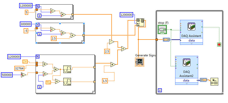
The fitting requires a fishing signal (32,764 KHz) saw tooth (0.3 Hz) signal output to drive the laser and acquires the signal from the output of the detector. I use the NI USB-6356 data acquisition with the speed limit of 1.25 MECH. / s.
I put the generation mode like "Samples continues", samples of writing/reading of 1.2 M and 500K (Hz) frequency in the DAQ Assistant. I also tried 500K and 500K.
The scheme of vi is illustrated in the following figure.
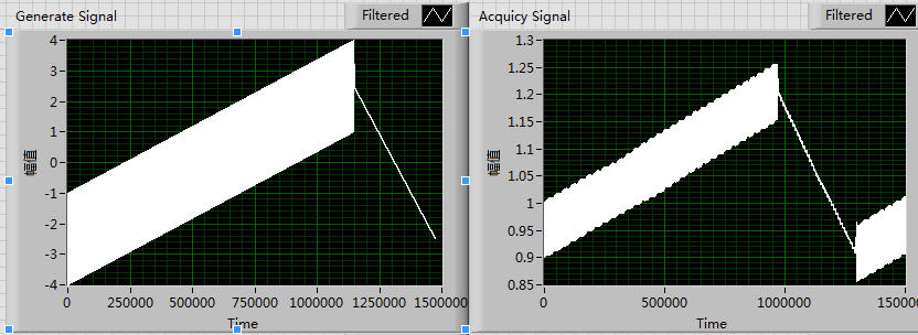
Of the front plate, the generation of signal is normal, which may be seen in the left side of the following figure. But signals a lot of periodic fluctuations that will appear if the right side of the figure. In addition, the siganl acquist go all the time.
I think it's maybe a few errors with my setting of the sampling frequency, I tried a lot of time for a change of pace, but it seems unnecessary.
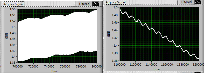
These fluctuations exist not only in the growing period but alos can be seen in the declining period, which is shown in the following figure:
I tried to solve this problem for almost a week and try a lot of different rate, but all fail.
Could someone give me any suggestions please? Thank you very much!!
Thanks SOSOSO much for your reply immediately every time!
This is my first time to write the Labview program with data acquisition
The attachment is the field of Vi.
I'll read the Web page that you offer, thank you very much once again!
Tags: NI Software
Similar Questions
-
The problem is in "Network Diagnostics Framework V2" Microsoft provider, and the OwnerHC is WinInetHelperClass. Files that describe it are: Eventlog.etl, which I did not open as my security system said it could be a virus and opening may harm my computer. There are a lot other categories and numbers on the report too, but I didn't know if I should include those. Help? Also, I can't install Adobe Flash Player, but I tried all night last night, without success. I can post a copy of the report, but I'm afraid I might give too much information that could come back and bite me in the yoohoo. Safety information that hackers live. Thank you.
Hi amal.
I couldn't figure out how to go in safe mode. Then I went to the event viewer and crossed logs and couldn't find the one I got. As sson as I can I'll add it to this topic.
When I install Falsh Player, it goes through the installation process, then disappears when I try to pull up. Not in the files on the desktop, nowhere to be found. Then I download the uninstall wizard, even though I have no idea if it was installed, then uninstall it. After the uninstall is complete, it says "Uninstall successful" or something to that effect. That if, I try to re install the same. He has done several times and abandoned.
So, it's the situation. Sorry it took me so long to get back to you. I appreciated your quick response however. I always have problems, but I used the Microsoft Mr. Fix, and I did not have error messages since then.
Thank you
Mary
-
Real-time display at the high frequency of data acquisition with continuous recording
Hi all
I encountered a problem and you need help.
I collect tensions and corresponding currents via a card PCI-6221. While acquiriing data, I would like to see the values on a XY graph, so that I can also check current vs only voltage/current / time. In addition, data should be recorded on the acquisition.
First, I create hannels to analog input with the Virutal DAQmx channel create, then I set the sampling frequency and the mode and begin the tasks. The DAQmx.Read is placed in a while loop. Because of the high noise to signal, I want to average for example every 200 points of the current and acquired for this draw versus the average acquisition time or average voltage. The recording of the data should also appear in the while loop.
The first thing, I thought, was to run in continuous Mode data acquisition and utilization for example 10 k s/s sampling frequency. The DAQmx.Read is set to 1 D Wfm N Chan N Samp (there are 4 channels in total) and the number of samples per channel for example is 1000 to avoid the errors/subscribe for more of the buffer. Each of these packages of 1000 samples should be separatet (I use Index Array at the moment). After gaining separate waveforms out of table 1 d of waveforms, I extracted the value of Y to get items of waveform. The error that results must then be treated to get average values.
But how to get these averages without delaying my code?
My idea/concern is this: I've read 1000 samples after about 0.1 s. These then are divded into single waveforms, time information are subtracted, a sort of loop to sprawl is used (I don't know how this exactly), the data are transferred to a XY Chart and saved to a .dat file. After all that's happened (I hope I understood correctly the flow of data within a while loop), the code in the while loop again then 1000 samples read and are processed.
But if the treatment was too long the DAQmx.Read runs too late and cycle to cycle, reading buffer behind the generation of data on the card PCI-6221.
This concern is reasonable? And how can I get around this? Does anyone know a way to average and save the data?
I mean, the first thing that I would consider increasing the number of samples per channel, but this also increases the duration of the data processing.
The other question is on the calendar. If I understand correctly, the timestamp is generated once when the task starts (with the DAQmxStartTask) and the time difference betweeen the datapoints is then computed by 1 divded by the sampling frequency. However, if the treatment takes considerable time, how can I make sure, that this error does not accumulate?
I'm sorry for the long plain text!
You can find my attached example-vi(only to show roughly what I was thinking, I know there are two averaging-functions and the rate are not correctly set now).
Best wishes and thank you in advance,
MR. KSE
PS: I should add: imagine the acquisition of data running on a really old and slow PC, for example a Pentium III.
PPS: I do not know why, but I can't reach my vi...
-
Treatment of LabVIEW data and high speed data acquisition C
Hi all
I am designing a data acquition VI high speed of 3 cards acquition of data at the maximum speed. Data cards are PCI 2517 Measurement Computing. The sampling frequency for each card is 1 M samples/second, if the total sample of M 3/second of three cards. Problem is the LabVIEW drivers and the screws provided by the provider works very well just for a single card at maximum speed, but does not support multiple cards at maximum speed. Their technical engineer advised me to write code in c#, C++ or VB.NET for this data acquition high speed. If I use C forever, I would like to use LabVIEW for processing of the acquired data to data acquisition. I came across a few examples that suggest the creation of dll C code and then calling it a LabVIEW. But those who have programs simple and none of them speak in C data acquisition. My questions are,
1. is it possible to call a C data acquisition program high speed of labview and not work in any kind of present of buffer overflow?
2 would it not simple best to use labwindows CVI?
3. is there another alternative solution that I'm missing?
I'll appreciate all the entries.
Thank you!
Nilesh-
It's pretty easy. Arguments for CINrun must match wiring. You can wire your CIN function block and say LabView to generate the C interface code to begin.
Here's my pairs for the ASIO audio project.
All the best,
Terry
-
Hello
I have a power meter which provide the USB driver and a Labview program to get the data and NI USB-6221. The project I am currently working on the needs of:
1 acquire two signals (inputs of simple tension), pressure frequency KHz
2. acquire a flow signal, the output signal is 0 to 5V pulse, each pulse means 0.4 ml volume. So I use a voltage inflows to count impulses in certain period of time (in this case, 1 S) for water flow. ; KHz sampling frequency and the 1 Hz update rate
3. acquire a signal of engine speed. The output signal is pulse square wave whose frequency is related to the speed. I use a REIT port to measure the frequency. Sampling rate: Auto
4 give output voltage sine or square wave, I use AO do that.output rate: Auto
5 acquiring by VISA electricity meter data. Data update rate: every 50ms
Currently, all the 5 tasks work well separately. But when I put them together, some signals are beginning to hang, for example, pressure signals sometimes give nothing.
Another problem is the data record. I programmed the VI in such a way that whenever I press the button 'save start', he begins to record data and save them in a .cvs file. For some reason, I always get only the data in the first table. Coult someone help me? I download my code as follows
Hello
What I meant by open, write, close. For any type of file you are using.
Open the file, which produces a reference, then put the mention in a registry to offset.
Write data, using the function write (for this type of file) and the reference.
When you are finished, close the file reference.
Writing in the spreadsheet opens, written, close all at once. It is very good for this type of application.
***
The issue of the loop is more general. I would like to say first of all, I want to say that since each loop works on its own, it is own VI, and that this program has put all this into a single VI, which has a method to solve the problem is to disable all the loops and allow them one at a time to see if there is a culprit responsible for.
Using multiple loops executes the code at the same time, and some loops would be cycle faster than others, especially if some of them are loops just as they are.
Communication between the loops is a test to the address if necessary.
Running all these signals through different loops DAQ must also be examined. Don't know what questions are for read and write somewhat randomly in the channels.
-
niHSDIO dynamic generation and Acquisition using LV configure Trigger VI
Hello!
My experience is limited within the environment of digital programming; Nevertheless, I have worked on this problem for a few days and would appreciate some comments if possible.
I am trying simply to generate and acquire a duty cycle of 50% of 8 MHz TTL pulse train on a PIN DIO of the PCI-6541 and acquire back from the signal on another axis of DIO. I have a connector corresponding to the embedded 6541 VHDCI connector which of course the generation and acquisition DIO welded pins to provide a loopback effect.
In short, I use the niHSDIO configure Trigger VI (instance--> start Trig: SW), niHSDIO send software Edge Trigger VI and write Named Waveform VI (instance--> data: 1 D U32) in the generation section. For the section of the acquisition, in short, I use the VI of waveform Fetch niHSDIO (instance--> single record: WDT).
I see results in the waveform acquired showing the generated and acquired digital TTL pulse on the respective DIO pins train, but I can't seem to get my 8 MHz frequency requirement. In addition, the lower part of the assignment of pin DIO, more frequency. Unfortunately, due to the configuration system required, I have confined myself to pin 12 DIO for the generation of digital pulses. Even with a 50 MHz clock frequency, I'm ~ 6 kHz of frequency acquired max. I looked at changing the parameters of the wave form VI named write, but it is not possible because the VI call a library function node. I also tried to generate a waveform of 8 MHz through a VI of generator of digital model, but I do not believe, you can trigger on generated waveforms? It seems that you must generate data using a simple loop to as a counter and sending the result to the waveform VI named write. Are there other ways I can simply generate and acquire a digital signal of TTL of 8 MHz (no external connection)?
In any case, any kind of feedback would be greatly appreciated.
Thanks in advance for your time.
Dan
Dan,
Sorry about the nomenclature. I usually use 0 x or 0 b for indication of radix, it is not necessarily a kind of standard, just what I used in my old days of the Assembly.
Looks like you have a knowledge about the data. Basically the material is just save in DRAM an array of words of 32 bits, with each bit corresponds to a data channel and each element being generated to the sampling clock rate you enter to your vi. Everything else is just easy data manipulation or usage. The interleaving method is just as I like to create a toggle model. You can easily do a loop with an inverter and feedback node or use on the construction in screws to signal generation. In addition, you can use the software digital waveform editor or control panel test to generate the county or toggle modes.
Give us an update when you enter the laboratory and let us know if you encounter any other disorder.
-
Doubts about the sampling frequency when the production and acquisition
When the generation and acquisition of samples, the maximum sampling frequency is the maximum sampling frequency Council divided between the generation and acquisition of task number?
Thank you
Hi Houari,
You should read the specifications of your box DAQpad!
It is clearly said: entered analog = 200kS/s rate sampling, but analog output = sample rate of 300 s/s or even just 50 s/s for the hardware timing!
-
The most effective way to log data and read simultaneously (DAQmx, PDM) high data rates
Hello
I want to acquire the data of several Modules cDAQ using several chassis to
high data rates (100 k samples per second if possible). Let's say the measurement time is 10 minutes and we got a large number of channels (40 for example). The measured data is written to a PDM file. I guess, the memory or the HARD disk speed is the limits. For the user, there must be a possibility to view the selection of channels in a graph during the measurement.My question: what is the best and most effective way to save and read data at the same time?
First of all, I use an architecture of producer-consumer and I don't want to write and display the data in the same loop. I expect two possibilities:
[1] to use the 'DAQmx configure logging.vi' with the operation 'journal and read' to write the data to a PDM file. To display the data in a second loop, I would create a DVR samples documented and 'sent' the DVR for the second loop, where the data will be displayed in a graph (data value reference). This method has the disadvantage that the data of all channels is copied into memory. Correct me if I'm wrong.
[2] use 'DAQmx configure logging.vi', but only with the "journal" operation to write the data to a PDM file. To view the selected data, I had read a number of samples of the TDMS file in the second loop (I'm currently writing the TDMS file). In this case, I have only one copy data from the selected channels (not), but there will be more HARD drive accesses necessary.
What is the most effective and efficient solution in this case?
Are there ways to connect and read data with high frequencies of sampling?
Thank you for your help.
You say that the measurement time is 10 minutes. If you have 40 channels and you enjoy all CHs at 100 kHz, it is quite a number of values.
In this case, I always try to approach under the conditions of use. If a measure is only 10 minutes, I just connect all PDM data and create a graphic module that could be in the same loop of consumers where connect you the data. You can always work on the raw data files big offline afterwards, the extraction of all the information you need (have a look at the product called NI DIAdem: http://www.ni.com/diadem/)
The main issue is that the user needs to see in the graph (or perhaps a chart can be useful too). Lets say that the graph is 1024 pixels wide. It makes no sense to show multiple data to 1024 points, Yes? Every second will produce you 100 data points k per channel. What is the useful information, which should see your username? It depends on the application. In similar cases, I usually use some kind of data reduction method: I use a moving average (Point by point Mean.VI for example) with a size of the interval of 100. This way you get 100 data points of 1000 per channel every second. If you feed your graph every second with these average values, it will be able to data points in 1024 of the store (as a default) by channel (curve), which is a little more than 10 minutes, so that the user will see the entire measurement.
So it depends on the frequency at which you send data to the consumer. For example, collect you values 1024 by iteration of the producer and send it to the consumer. Here you can make a normal means calc or a bearing (according to your needs) and he draw a graphic. This way your chart will display only the values of the last 10 seconds...
Once I programmed some kind of module where I use a chart and not a graph, and the user can specify the interval of the absolute timestamp that is traced. If the data size is larger than the size of the chart in pixels, the module performs an average calculation in order to reduce the number of data points. Of course, if you need to see the raw data, you can specify an interval that is small. It all depends on how you program zoom functions, etc... In my case I hade a rate of 1 Hz, so I just kept all data in RAM limiting the berries to keep 24 hours of data, so that technicians could monitor the system. In your case, given the enormous amount of data, only a file read/write approach can work, if you really need access to all of the RAW data on the fly. But I hope that the values of working capital means will be enough?
-
Hello
I can't find acquisition of ICP data and Signal Processing controller, memory controller PCI bus controller SM for HP EliteBook 840 G3 running Microsoft Windows 7 Enterprise (64-bit).
Any help is greatly appreciated!
Hello:
See if this driver works...
-
Difference between DAQmx DAQmx Base and acquisition of Legacy data
Hello
What is the difference between NI-DAQmx, DAQmxBase and acquisition of data Legacy and what are the characteristics of these materials
See this FAQ.
And it's the software, not hardware.
-
Digital and analog generation and acquisition using USB-6251
Hi all
I have to actually synchronize a 6251, USB and USB 6366 Board. I have a vi, which is good that now I am able to use the 6366 as the master and as slave 6251, attached tie. The master generates a digital trigger for (generation synchronization) pulse and the acquisition of the signals on both cards, analog signal ramp and acquires signals. The slave acquires only a series of signals after outbreak.
I want to have the 6251 as master and as slave 6366. The vi attached the other way around as I mentioned above. When I try to use the 6251 as the master, I get an error asking me to specify the clock source (I did the material and some changes in the program as well, as export properly 6251 at 6366 clock).
Thank you
SANJU
Thanks for your reply jonathon,
But in your code below, I coudnt get the Outpput internal PCI-6251/ctrl0...
but I hardwaired the o/p (PFI 12) meter... .and generated a signal meter on this port, I used that as the clock...
Thank you
SANJU
-
HP 15-r212nv (Energy Star): acquisition of ICP data and Signal Processing controller
There is a device in the device manager that recognizes my phone and I can't find drivers! Acquisition of ICP data and Signal Processing controller. I searched the web, but nothing. My laptop is HP 15-r212nv model and I'm under 64-bit Windows 10.
Thanks in advance
Hello:
See if this driver works...
This package contains the driver which allows Intel platform dynamic and thermal firmware setting. Intel platform dynamic and thermal environment information system temperature and power use for the thermal protection of the system to work properly. This package is provided for the laptop models running a supported operating system.
File name: sp71262.exe
-
Hi all... I learn LabVIEW since few days.i want to acquire a signal of pc6251 of acquisition of data and perform fft it can u people please help me? Thanks in advance
If you do only use LabVIEW for a few days, you should get familiar with it first by looking at some of the resources available here. After that, you can watch heredata acquisition.
After reviewing these documents, you can post back with any specific questions.
-
Acquisition of data and filtering on FPGA
Hi all
I have trouble to design a FPGA program for acquisition of data and filtering.
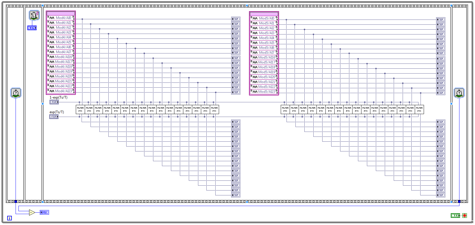
I have two NOR 9205 modules configured to work in terminal mode of DIFF, i.e. There are 32 entries this program must read every Ts seconds. (Ts is the time discretization, i.e. during the period of loop)
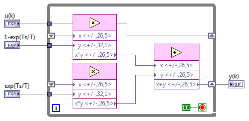
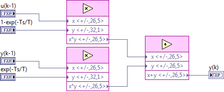
With respect to the digital filter, I implemented a possible simple filter with transfer function G (s) = 1 /(1+sT), which is part of the field of discrete-time equal to y (k) = a * u (k - 1) + b * y (k-1), where u is the original signal, and there is filtered signal. The coefficients a and b are equal to: a = 1-exp(-Ts/T), b = exp(-Ts/T), and T is the time constant of the filter (usually T > 5 * Ts).
The implementation of main program for the acquisition of data and filtering are:
This application is for the digital filter:
However, the problem is that this program cannot take the FPGA resources on cRIO-9114, and Yes, I tried to define the criteria of compilation for the area. I also tried to implement the multipliers in digital filter as lut and DSP, unfortunately without a bit of luck.
Because I don't have that much experience in programming of FPGA, someone has any suggestions how to improve this code to adapt existing FPGA resources?
Best regards
Marko.
Hey Norbert_B,
I managed to solve the problem. First, I changed the reentrancy of Preallocated incoming execution clone to not reentrant execution. As no reentrant VIs have States, I had to use the node of the feedback to the main VI to get u(k-1) and y(k-1). Another important thing is to choose Ignore FPGA reset method in the node of the properties of FPGA implementationfeedback, since in this case, the feedback node uses less resources.
Here is the new main program VI:
And here's the 'filter' VI:
Thanks for the help!
Best regards
Marko.
-
SQL help, how to group in column A and then get a higher frequency in column B?
Assuming that the following table, operation represents each type of operation of transaction
Employee table operation another column c
' < ' id1
' < ' id1
' < ' id2
' *' id3
id1 ' / '.
question, for each operation, which employee do the most? which employee do the 2nd most?
I thought I need to group by operation first, then get the frequency of the employee and get top 1, or at the top of page 2 of higher frequency.
But I'm struct and don't know how to write sql code.998408 wrote:
Assuming that the following table, operation represents each type of operation of transaction
Employee table operation another column c
'<'>
'<'>
'<'>
' *' id3
id1 ' / '.question, for each operation, which employee do the most? which employee do the 2nd most?
I thought I need to group by operation first, then get the frequency of the employee and get top 1, or at the top of page 2 of higher frequency.
But I'm struct and don't know how to write sql code.Welcome to OTN. OPS! Posted in the wrong forum. Just after in {forum: id = 75}. Before posting it close this thread as answered marking.
If someone answer is useful or appropriate, please mark accordingly. *

Maybe you are looking for
-
iPod classic 160 GB will not appear in iTunes
My iPod Classic 160 GB stopped suddenly appears in iTunes yesterday. He always shows up on my computer, however. I tried to reset my iPod. Then I tried to restart my computer and iPod. Then I tried to update the software from my computer and iTunes.
-
Read analog output channel value internally
According to this you can read the values of analog output of return without having to physically connect the wires. By using the technique described in the example given (DAQmx_Read_Output_Internal_Channels.vi) I'm reading a current area of OCCUPANC
-
error installation w2207h Monitor driver
I have a Pavilion a6600f, visat home premium 64-bit. I have just purchsed a (w2207f) 22 in monitor ho; I'm having a problem installing the 9either driver from the CD provided or that I can download on the HP website). He just told me that an error ha
-
Question about Powerconnect M6220 and out-of-band/management 8024-K connection
I'm sorry if this question belongs to another section, but with regard to the functionality of these switches I thought I would start here. My question is, the M6220 and 8024-K out-of-band connection are going through the connections on Board (for ex
-
Smartphones blackBerry the screen started to Flash
I noticed that the screen started flickering on my blackberry 8520. Then all of a sudden he went and I can't turn it back on it. I tried to take the battery out and it put it back again and that has not worked. Someone knows how to fix this?