graph to build a 3D
Hello
I would like to build a 3D graph from data stored in several files just to read United Nations United Nations perono.
each file contains 2 columns: 1 frequency, amplitude column 1 column
the reading of each of these files, amplitude curve I trace a = f (frequency) en using 'building a gaphe XY '.
And more I wish I could build a lively en 3D graph where each of its curves would "Supplement" past each other as and when we trace them.
I wanted the UTI VI "on the surface 3D", but I find myself blocked by a format incompatibility problem.
Know someone help me tracers my 3D graph?
Thank you in advance
Anne
I struggled but I think it's about what you want!
Tags: NI Software
Similar Questions
-
Alignment in a graph where build problem
I would appreciate your help.
I turn around to try to align a legend of a graph.
My application is coded in Labview 2014 in Windows 7. Before it was on XP and LabVIEW old and I had no problem.
I have a user with a graphic interface. I did my good interface look. When I build the interface is not the same in the exe version. I have a copy of what should look like the interface. I also have a copy of the interface in the EXE. In the image of the exe, I circle the part which is not align. Is their way to correct that?
Thanks in advance!
I solved my problem with the creation of a control of typedef with my chart. When I first open the control to customize it, I notice that if I try to change something on the chart legend Dungeon are dwindling. Probably, the size it is in the EXE file. So I tried to adjust size so that the size does not resize itself in the window customize. Then, with the setting of the size, I create the exe and the size has not changed.
I hope this can help someone else!
Thanks for your help
Cynthia
-
using advanced for a graph Query Builder
I'm trying to insert a chart based on a query in my report model. However, the data comes from a text file; so I create the object of the request for the chart of the analysis of the text file. However, the "query.name" and "query.number" fields do not change for each record in the original report query - only the first record is used. So the first card on the first page is correct, but the map never changes for all other pages (each page represents one record in the query). That's what I put in the advanced query designer:
< cfset ThisQuery = QueryNew ("ItemColumn, ValueColumn") >
("< FileExists("D:\charts\#query.name#_#query.number#.txt ") cfif >
< cfset ThisDataItem = 0 >
"< cfloop file="D:\charts\#query.name#_#query.number#.txt "index ="$thisline">
< IsNumeric ($thisline) cfif >
< cfset ThisDataItem += 1 >
< cfset QueryAddRow (ThisQuery) >
< cfset QuerySetCell (ThisQuery, "ItemColumn", ThisDataItem) >
< cfset QuerySetCell (ThisQuery, "ValueColumn", $thisline) >
< / cfif >
< / cfloop >
< / cfif >
So basically the file name is set according to the first row (result) of the report query, but then the file name (and thus the graph) never change even if all other fields based on a query on my page change correctly (all other queries. BlahBlah fields to update correctly). Is this a bug? I don't think I was doing anything too crazy.Phew! I found a really great solution, which has a ton of uses.
First of all, like I should have made, ANY variable in a coldfusion tag will be figured out when the report is called, not for each query result. In other words, the query.xxx or report.xxx or anything that's NEVER going to work properly inside a tag, not even in a report feature or Advanced Query Builder.
However, there is a simple way around this. Simply make a function in relation to the arguments and in the editor of your field expressions calling the function, and pass query variables or State:
#report.yourFunction (query.field1, query.field2) #.
You can do all sorts of magic of Coldfusion function and return any shape desired result.For my particular example (creating a query object for a chart to insert dynamically), I had to add a step is not so obvious: create the object of my application with a shared (in this case, the scope of the request) scope, otherwise the variable is trapped in the scope of the function. So it was my solution: I had a chart with the option 'Print when' my function call "getChartQuery" (from query variables, of course). The function built "Request.ThisChartQuery" and returns True if there's something in there (the logic of "Print when" uses the Boolean value of whether to display the graph or not). My card is always based on a query, but the Advanced Query builder has NOTHING in it, with the exception of the variable that contains the query object ("Request.ThisChartQuery").
There is another solution, I found where the report function makes all of the chart (using cfchart tags, etc.) and saves to a PNG file and then returns the path to the image. Then, you simply add an image field to the report, and you use the expression builder to call the function. Well, hope this has helped someone!
"EDIT: the references are" " http://www.adobe.com/go/ee54cc6" and " http://www.houseoffusion.com/groups/cf-talk/thread.cfm/threadid:40786"
-
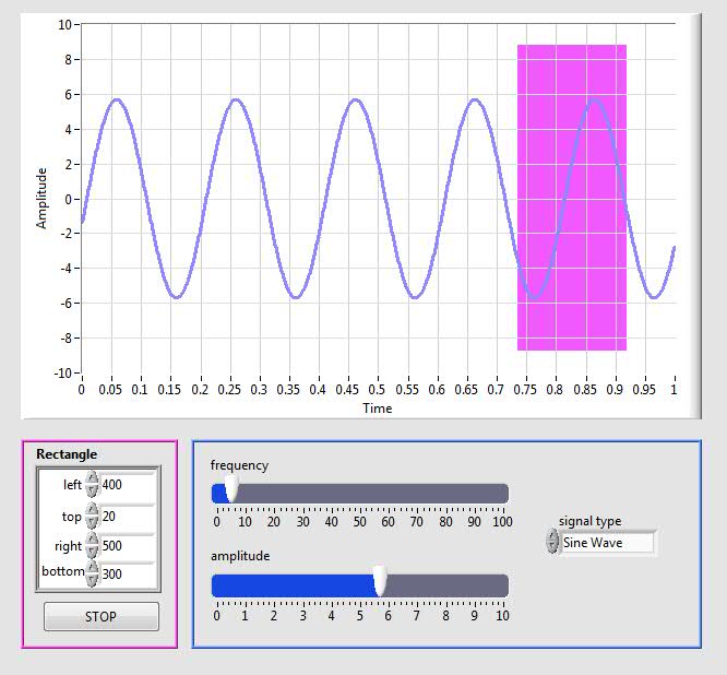
Hi, I want to programmatically draw a rectangle on a chart XY (XY Graph.vi Build). I know where the 4 points are on the coordinate chart but I can't yet draw using the block Rectangle to draw. Could you please help me how can I draw a rectangle in a graph. I am attaching the photo to this message
Hi guys,.
I thought it was interesting questions - and, although I had not tried anything quite like this before, I thought I would give it a whirl. smercurio_fcsuggestion was excellent - I find the code referenced in LV example finder, in the fundermentals > graphics & graphics > plot pictures folder.
Attached are 2 pieces of code.
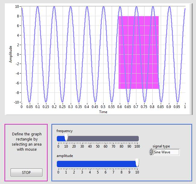
DrawRectangle on Graph.vi allows users to define the rectangle by cluster of façade.
DrawRectangle on graphic .vi (events) allows the user to define the rectangle by clicking and dragging on the chart. Please note that the code requires that you start from the upper left corner of the rectangle, and drag to the lower right. But isn't that a creative logic would not solve - if you wanted a bit more flexible code.
You should also know that I have not spent a lot of time on the code, so it is not perfectly architected. But we need to think!
Best wishes
-
Build the table to 2 dimensions to plot a graph from UIMessages
Hello guys,.
I need some advice, the problem I have is that I want to pass an array [0 5] numbers to my throwugh of custom UI UIMessage to plot a graph with these data in the same grapgh (see the behavior of the 6 signals on the same graph), but so far I could only pass a value and see only a signal in the graph.
Is there a way to pass the french table UIMessage using the activeXDataParam? Or may be otherwise?
Thanks for your comments.
Eder
I threw together a simple example in TS 2014 and 2014 LV. I think it does what you want. Simply run the main vi in the project and select the random sequence file Array.
In addition, attached is a photo of my UserMessage vi.
Hope this helps,
-
I have problem with making XY Chart user friendly. In my case loop execution time-out will be variable, so I can't use waveform graph because calendar like - look at the picture of vi.
How can I do XY graph from the far left position, no use autoscale and use x axis scrollbar?
Thank you
Zoran
All shafts are set autoscale, so you shoud turn that off.
It is probably a bad idea to cultivate endless datasets inside "express mount VI xy graph", would be an easier solution to manage to make your own history of fixed size buffer. Use an action engine, for example.
Anyway, so that the x-scrollbar is visible, the x-range data must be wider than the x-axis range. You could just update the max and min according to the current time, for example as follows. All this requires more work, for example, you don't want to update the settings of the range while the user scrolls.
Also:
- You do not need the local variable, simply put the stop action button th latch.
- Convert to DBL time instead of post EXT does not make something useful in this case.

-
Build the AOSPS (unknown Baseband, flicker and recovery graph)
Hi people,
I have changed the AOSPS for awhile for Nexus devices and maintains also a few threads on XDA.
I have now moved to the Xperia Z3 and started to set up my build environment, as shown here.
I built and after the first start-up, I can not work because of the unknown baseband radio.
I spent some time on XDA to find answers and followed this http://forum.xda-developers.com/crossdevice-dev/sony/how-to-build-custom-stock-kernel-linaro-t306691... but still baseband unknown.
I post here because I hope that some of you got the answers.
Second, the graphics, already during the startup, sparkles around the area of the softbutton. All commits in Git that could help prevent this?
Finally and above all, get a return to work on the device after the flash of the ROM is also a pain. I took an a CM ROM with recovery included, flashed Gapps boot.img and re-flashed my boot.img so successful but is still just a poor work - around.
Thanks for your help :-)
Hi, first of all thanks to increase my status as a rookie to the learner. The learner wants to sum up its experience to build the AOSPS for the Xperia. Since I've already built for Nexus devices for years, I thought that the Xperia cannot be too difficult to build software for.
1 building AOSPS will not a radio works but find you some codes in Git. I still had questions about wasting time on reboot very probably due to bad binary files (already had it on Nexus also). 5.1 construction will lead to graphic flicker but the 5.0 building, which still uses the core 3,4, doesn't have this problem. There is no way to get the camera work, so it was a reason for abandoning the Nexus for the Xperia devices. So I started building CM.
2 building CM works well. Recovery can be added easily (what cannot on AOSPS). Although version 12.1 (5.1.1), CM still use issues 3.4 kernel so not on the graphics. It is also comes with a camera works but the photos are storted (probably because of the lens wide angle).
I am very disappointed. Has now spent nearly two weeks to find that any building ROM still will not lead to have a ROM works fully. Also, get comments here seems to be difficult, but we, people come here to get questions... I hope that we will get the binaries for the phone soon to build a ROM that had already been built on other devices for years... the Xperia must return in the package. :-(
-
Satellite A210-183 has error message "FAILED to RENDER GRAPH"
Hello
I recently bought a Satellite A210-183 with an AMD processor Turion 64 X 2, 2 GB of memory, ATI X 1200 graphics card 1.3 build in webcam and possibly other features.
After 1 day use and that I had tried all the features and worked normally, when I tried to open my webcam, I got the message "FAILED to RENDER GRAPH"...
I restart the laptop and once worked normally and other time showed the same message. I decided to return the labtop back to the store to change because there's a term in this store that modify the machine within 7 days after purchase.
Certainly, the shop change the labtop with a new one. When I started again some of my programs installed on the labtop such as (msn & yahoo messenger, Nero, office, Sony ericsson Pc Suite and other programs of 1-2 and I had already tried to use the webcam and worked normally) after some restarts, I get the same message when I try to open the webcam... "" FAILED TO CHART RENDERING.
Everybody knows why I received this message and I can not open the webcam? I get on crazy and I do not think that the problem comes from the labtop. Perhaps something else like a program operating...
Please someone with something similar helps me.
Thanks in advance
It seems that this problem could be linked to the issue of software.
Try to update the graphics driver and the driver for the webcam.Notes; you need to remove the old drivers before you install the new version.
By the way; If you have problems using the webcam with the MS Messenger then check out this thread:
http://forums.computers.Toshiba-Europe.com/forums/thread.jspa?MessageID=102403Greetings and dude good luck
-
Hello
How can I make graph XY with the Web of LV user interface Builder?
In the palette of cluster, there is a function of Point of Bundle.
Use it to create the type of data Point.
Build table to create an array of points.
Wire the array of points to the final curve.
Thank you
RAM Kudukoli.
-
Build table 2D-the only condition of case string
Hello
I'm having a problem when I am trying to build a 2D of the elements of the string table. Here's basically what I'm doing:
I'm loading the tables in different text files (Session_001.txt, Session_002.txt, etc.) and concatenate into 1 big table.
On each line of text Session files, there is the session number, various characteristics of hockey sticks, and then a couple results.
I want to be able to select the various features and then display the corresponding results. Currently, I'm working on the selection of the Session, and when I get this working, the rest would be similar (I guess).
The problem I have is that when I select the sessions that I want, the Array3 resulting (with all data) is filled with empty lines (table 1 d of the empty elements). I had the same problem when display a table 1 d (table 2) coming to show what Sessions had been selected, but I managed to fix that by searching for and deleting empty elements.
The problem lies within the structure of matter I. I compare all the elements in the first column of my huge 2D array with each number of the selected Session, and when it is 'true', that I keep the current line to go to table 3. If it is "false", nothing should happen (I have a registry change through my case 'false', but a line of empty strings is added to the table.
What Miss me?
I know this probably sounds very confusing, so I join you the only VI and a zip containing the VI and my text files.
Thank you!
Off topic (Finally, still on the topic of my VI), it will be possible to assign a different color for each type of stick (MX3, APX3) or the different type of marker for different types of shots (WS, SS), etc., when I want to display the results on the same graph? If not, stop now and I'm going to Matlab.
Oh my... Equal to true. I'm so ashamed.
I just started Labview on my internship 2 weeks ago. There are probably several simplifications I can do for my screws, but as long as they work and do not burn my laptop, I agree.
With respect to the conditional tunnel, I n, t really know to use it yet, but I found the problem with my registry to offset. I created a 2D array empty outside the two loops and added a registry to offset. I then build I tried to rely on another thread.
Resolved VI is attached to anyone who cares

-
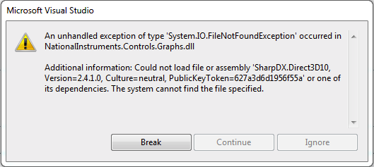
NationalInstruments.Controls.Graphs.dll System.IO.FileNotFoundException
Hello
The application I'm working on contains a few plots. All the functionality works great on my machine. However, when I built in release mode, and then test it on another machine (tried all the targets, x 86, x 64 and no matter what CPU), the application breaks down. The graph seems to load fine, but it seems that the accident occurred when the data are supposed to be added to the plot... In the crashdump, I see the following error coming
There is no reference to SharpDX in my project, and I'm assuming that this dll is used by Graphs.dll. How can I solve this problem?
Thank you
SharpDX*.dll meetings are used by the WPF support DirectX rendering. It was a new feature introduced in Measurement Studio 2015. There are 6 sets, and they are only in the GAC:
- SharpDX.D3DCompiler.dll
- SharpDX.Direct3D9.dll
- SharpDX.Direct3D10.dll
- SharpDX.Direct3D11.dll
- SharpDX.dll
- SharpDX.DXGI.dll
These are in the C:\Windows\Microsoft.NET\assembly\GAC_MSIL\SharpDX* files (each assembly has its own folder). If you copy these and put them in the same place that you run your executable from, they should work perfectly.
The new installer Builder that comes with Measurement Studio 2015 will also handle this automatically.
-
graph waveform of several sensors
Hi, I receive data from 50 sensors with a microcontroller. Data from the sensors are stored in LabVIEW in an array of cluster, each cluster containing a unique sensor info. I need to display a graph of trends of the curve of value 3 of all sensors, so that each sensor should be represented by a color. The data are updated every minute. Can someone help me please?
First of all, I'm sure you want a graphic, not a graphic. A graph keeps a history. A chart shows just the last thing you wrote for her.
Secondly, to make the building of the waveforms within the loop FOR. Makes things MUCH simpler.

-
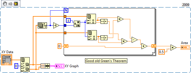
How to calculate the area of a XY graph
I have build a process assessment program and got stuck on it. I have a chart XY of the angles of knee hip x and need to find the area of the plotted curve. I searched the forums, but found no way to do it. Any ideas?
Green theorem comes immediately to mind:
I cut the first two points to make the graph more cyclical and 1300.36 for the answer. That passes the eyeball test, but you should double check my implementation of rapidfire (and my memories of summary calculation).
-
XY graph multi plot points and color control live
Hi all
I'm doing something that should be simple, but difficult so far. I had a good look through previous topics and found similar things, but not really what I want.
In my experience, I'm scanning intensity vs. wavelength.
Ideally, I want to be able to:
(1) scan and see live plotted points.
(2) then I want the plot to stay on the graph when I run the following analysis, etc.
(3) I have an arbitrary number of scans. for example to start a scan, I press a button, an arbitrary number of times.
(4) I want to make sure the current analysis is drawn live in (red), and all the previous analyses are drawn in a different color (blue).
(5) sometimes I want can erase the graph of all scans and start over, without having to stop the VI.
Items 1-3 can be supported easily by placing the XY graph building and the XY graphic object inside the loop that runs the scan and uncheck 'clear data on each call' in the properties of graphic generation. See the first VI attached.
However, at the beginning of an analysis, she joined the last part of the previous analysis up to the first point of the next scan.
The difficult parts are 4 and 5.
For article 4, you need to build an array of plots, which is easy if you know the number of plots, but here the number is arbitrary. So, how do I do that? I had a go trying to use Insert table in different ways, but I haven't worked on it. Then if all goes well using the graphics property XY nodes I can adjust the colors of the plots.
For part 5 is not just enough to use the invoke = node reset by default, and have a button that executes the node. This clears the graphic but then when you run the following analysis all parcels previous pop up once again, indicating that the table that stores the plots is not actually deleted. The second accessory shows how I delete the chart.
My biggest problem is point 4 and combining point 4 and 5 together.
Help, please.
I fixed the problem of the route doubly table and added in the desired color, attached plot.
The code now done everything I wanted to in my first post.
No doubt the code could be improved more, but that's for everyone out there who has this problem.
Thanks to tst for give me useful advice.
-
Graph waveform repeats with each iteration of the loop
Hi guys,.
I got some great responses from you many already, so I hope you can help me once more!
I try now to simply take a voltage that is measured by a sensor, I tied to AI1, and I built a graph of very simple waveform using a DAQ assistant. I have the setup terminal to CSR, the acquisition value continuous sample mode and read samples and rate game to a control on the Panel before which I can control myself. All this is a while loop that is needed to collect data over time.
However, the problem I have is that for each loop of the loop, it seems, to reset the graph, so my x-axis never increases over time, ideally I want it to do is to show results through from 0 to 100 on the x-axis to say, and then, when it comes to 101, he will start again on the extreme left of the graphic to the right to a crossing another 100 points given) (there's a term for this, but I forgot, sorry!). To be honest, this kind of logic like everything in the loop will be restarted, but after trying to chart the loop it does not work, so I'm fresh out of ideas.
I think I might have to do is to manually build segments of data acquisition (DAQ mx) and have only certain parts of them in the loop, although I can't be sure. I tried various examples and online on the database of NOR (including tension-int acq & graphic clk which works well in the examples, but not at my request) but no luck for now

If anyone can think of what could be the problem, then please let me know. FYI the sensor is optical fiber if it makes a difference. I have attached the file VI that I did does not really...
See you soon!
Ritchie
Since you use a chart there is no way to fix it. If you choose to go to a XY chart you could solve this problem. See the example below.


Maybe you are looking for
-
See above - there known problems with these applications?
-
Hello I'm new with labview and I need your help. I want to execute exe file (including USB) on the system without labview. I create "Installer" and added "NI Labview Run Time Engine 2011" and "NI Visa TERM 5.1" ". but the USB is not working!
-
How do I finalize a cd after having burned to a cd - r
After the extraction of a cd when I burn it to a cd - r blank it will not play on a cd player is only in the car or on my laptop need help?
-
I recently bought a hp photosmart C4580 all-in-one, I was wondering if it is normal that my printer to launch a test alignment whenever I turn on the printer, and if not, how can I stop this from happening? Message edited by daviemcharg on 09/23/2009
-
Computer began to 'hang up' or randomly freeze for periods of a few seconds to a few minutes when you use Windows Mail, Internet Explorer, Firefox, etc.I tried to do a "restore" to factory settings on the advice of the manufacturer of the computer, b