Graphic multiplot XY: bug in LabVIEW?
I started a chart XY simple concession with this array of points, a point being a cluster that contains an x value and a value of y. It worked fine until I wanted to a multiplot XY Chart.
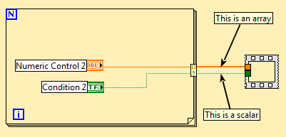
According to the detailed help of the XY graph, it must accept an array of clusters of plots, where a parcel is an array of points. A point is a cluster that contains an x value and a value of y.
Everything what I try, it does not work. I've included this example where I got a cut wire.
The example also shows the other option to display the graph XY multiplot and it works but then I have to redo a lot of coding.
Thanks for helping me!
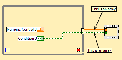
I found the solution and as a thank you for the attention, please find two ways to display multiplots on the XY graph.
Tags: NI Software
Similar Questions
-
Possible bug in LabVIEW with help chart
The attached VI reads a group of bytes as U8 from a file and writes the each other in a new file. It does this by using the function array decimate. It seems that there is a bug in LabVIEW. If the '+ 0' is deleted from the code nothing but 0 is written to the file. If you explore the table that will be written in the file it shows no null values, but the resulting file is always all zeros. Addition of '+ 0' was a work around the issue.
I'm under LabVIEW version 8.5.
This looks similar to the LabVIEW 8.5 suspiciosly bug, we discussed quite earlier.
Try placing a primitive 'always copy' (from the palette ' application control... control memory') until the file write and see if things improve. Good luck!
-
Graphical waveform Linestyle Bug?
Hello
I found that problems associated with the waveform diagrams and line styles in LV2016. If I change the line style of a multiplot for long dotted graph, the plot is changed for long dashed, but if new values are added, they will appear as short rushed. If there are other long plots dashed, they are modified short wiped out too. It happens with all styles (modern, classic, silver).
Everyone knows about these problems? Try again with the example below.
Niklas
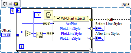
The good news is that you are not crazy, LabVIEW 2016 's erratic behavior. In an attempt to discover what had happened and who was responsible, I wrote a little routine to read and set the Styles of plot line for graphic signals 2 consecutive values from 0 to 4 with a variable delay (so I could put 0, 1, 2, 3, 4, or, say, 2, 3, 4, 0, 1).
My initial code read the line Style, and then return. I could tell by looking at the plot that something wasn't right, and if I ran it again, I could see what values were used. For example, if I put 0, 1, 2, 3, 4, I had 0, 2, 2, 3, 4, while 1, 2, 3, 4, 0 gave me 2, 2, 3, 4, 0. Since I did the reading before writing it, I needed to run the code twice to see what did the writing, so I changed the code to read, write, read, as shown below:
(The error shown above, dotted line was 'dug' NiklasN While loop to ensure that ran first).
Either incidentally, I added the delay time within the loop "just in case" LabVIEW need time to "adjust" the plots - I think it is probably indifferent...
To my surprise, the line Styles after were exactly what I expected - with an offset of 0, 0, 1, 2, 3, 4. However, if I immediately revived this code, the front line Styles (which should have been 0, 1, 2, 3, 4) were now 0, 2, 2, 3, 4, false! Also, if you look at the plots when you run the program several times without change to the Offset, you see Plot 1 change the appearance (probably when my 'put' loop runs) and then switch again as the numbers start to come there.
I just called Tech Support, made to this post, attached the code illustrating the problem (so they will have something to test), and I expect that they will confirm the Bug and drop off a CAR (report on the Corrective Action) to solve this problem. Thank you, NiklasN, to describe this issue.
Bob Schor
-
"Decimal string to Number.vi" bug in LabVIEW 2009 SP1
The "decimal string to Number.vi' seems to be the conversion of the input data in the type int32 internally even when the input tape in vi data is expanded floating point (no points of constraint). This is causing me grief. See attached vi
This bug is still present in LabVIEW 2010?
Thank you
Richard Ballantyne
There is no bug. You use the wrong function (see Help) If you want a floating point output. Use Fract/Exp string to a number.
-
Agilent 4156 bug or Labview driver bug?
Hello
I use Labview 8.5 for Agilent 4156C for certain measures customerized control. Now, I have a problem. I need to configure at least 3 SMEs. I chose SMU 1-3. I'm changing the sample program that come with the 4156C under labview driver installation. The problem is that when I use the Sub - VI Channe configure from 4156 Panel to change the configuration of SMU3 and SMU4, there is a message of error-1074000000. I choose simply SMU1 or SMU2 for the same operation, all right. What I did wrong, or there might be a few bugs? Thank you!
BTW, when I was looking for drivers for this equipment, I found 3 possible pilots with the keyword 'Agilent Technologies 4156C' and 'HP 4156C '. Are there different between these 3 drivers?
Evander
-
Can someone provide details on this known bug Labview? I can't find someone else who has experienced, and I would like to know what is the solution.
http://www.NI.com/PDF/manuals/374737a.html
412592
Cannot run VI FPGA in interactive mode (run button does nothing) if LabVIEW by default directory has been changed.
Well, it is set in 2014 of LabVIEW.
The problem is described in KB 4W7H2TNX: http://digital.ni.com/public.nsf/websearch/EF29C73D69B4887E86257592007C5AE5
It seems that the problem is exactly what describes the title, in that you could not run the FPGA VIs interactively if LabVIEW has been configured to a default directory.
-
Hello
I'm working on a project to map speed and rpm of a vehicle over time on axis x. I have sucessfully maped on an XY graph with speed on the right side and rpm on the left. Now, I want to change this representation in a stacked structure, but only with the help of a xy chart chart... I have. e using the same x-axis... and consider a range of woth speed rpm and 250 a range of 8500... then the graph must have 0-250 on the y-axis and the just above the 250 mrgin wide should start again from 0 up to 8500... is it possible...?
If Yes... Please help me. I'm working on LabView 7.1 and I have access to labview 2011 also.
Thank you
Rémy
Sorry about that, I forgot that the ILO.
Please read this: http://digital.ni.com/public.nsf/allkb/049C7E362BE4270A8625756E005CC46F
If this isn't what you're looking for, take a look at this: http://forums.ni.com/t5/LabVIEW/multiple-y-axis-with-different-scale-on-a-xy-graph/m-p/1731336?requi...
-
Cursor value Y set of linked graphics, no error (BUG)
As seen here when you set the value y of the cursor associated with a graph, the cursor is not moved (because the values can be duplical), but this action does not return an error.
This is a bug in my humble OPINION!
Tone
Your dear,
I was able to reproduce this problem with a simple VI; This is reported under investigation under the CAR # 165613
Thank you for bringing This issue to our attention.
Best regards
-
How do I display two signals graphic multiplot
Hi, I am currently working on a LabVIEW program that requires me to display two signals measured by two current using MyRIO sensors OR. I am facing problems displaying two signals on dashboard of data, I know how and what should I log in the block diagram Front Panel of LabVIEW so that both signals, measured by the current sensors can be displayed on the dashboard of data?
-Introduction to LabVIEW: http://www.ni.com/getting-started/labview-basics/ and http://www.learnni.com/
-Check the labview\examples\general\graphs\charts.llb for examples of the waveform card: https://zone.ni.com/reference/en-XX/help/371361J-01/lvconcepts/types_of_graphs_and_charts/
-Examples: http://digital.ni.com/public.nsf/allkb/21E8163F259DA2058625703B007511AA , https://decibel.ni.com/content/docs/DOC-40940 , and https://decibel.ni.com/content/docs/DOC-5574 -
bugs in LabVIEW 8.6 or "office 2007"
After you perform a clean installation of LV 8.6, I made a compilation of 'mass' on the record of the "addons\_office". However, the operation completed with errors:
# Compilation mass departure: Fr, 30. Jan 2009 19:11:09
Directory: "C:\Programme\National Instruments\LabVIEW 8.6\vi.lib\addons\_office".
# Bad VI: "borders and shading constant (Table) Shell.vi" Path = "C:\Programme\National Instruments\LabVIEW 8.6\vi.lib\addons\_office\word.llb\Borders and shading Constant (Table) Shell.vi" "
# Bad VI: "borders and shading Constant Shell.vi" Path = "" C:\Programme\National Instruments\LabVIEW 8.6\vi.lib\addons\_office\word.llb\Borders and shading Constant Shell.vi ""
# Bad VI: "withdrawal and spacing Constant Shell.vi" Path = "C:\Programme\National Instruments\LabVIEW Shell.vi Constant 8.6\vi.lib\addons\_office\word.llb\Indent and spacing"
# Bad VI: "Constant Shell.vi of the line and Page break" Path = "C:\Programme\National Instruments\LabVIEW Shell.vi Constant 8.6\vi.lib\addons\_office\word.llb\Line and Page break"
# Compilation of finite mass: Fr, 30. Jan 2009 19:11:25How is it that NEITHER provides a set of tools that even does not compile without errors? I am amazed and completely disappointed!
Herbert
Those are merge screws for pallets. They're meant to be broken. Everything will be ok.
D
-
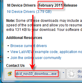
[Bug]? LabVIEW 2010 SP1 - Device Drivers Incorrect link
Hello
This page link to download LabVIEW 2010 SP1 Device Drivers Feb 2011 on this page points actually to November 2010.
See you soon
-JG
-
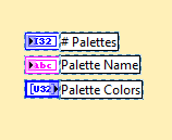
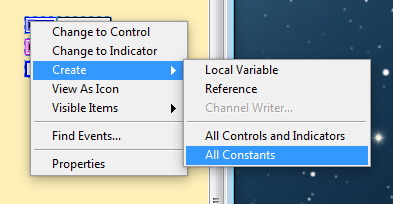
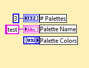
The shortcut of the comics 'Create all the constants' cannot create a constant to a control when it is mixed with flags:
Colors of the palette is a table control, the other two are indicators.
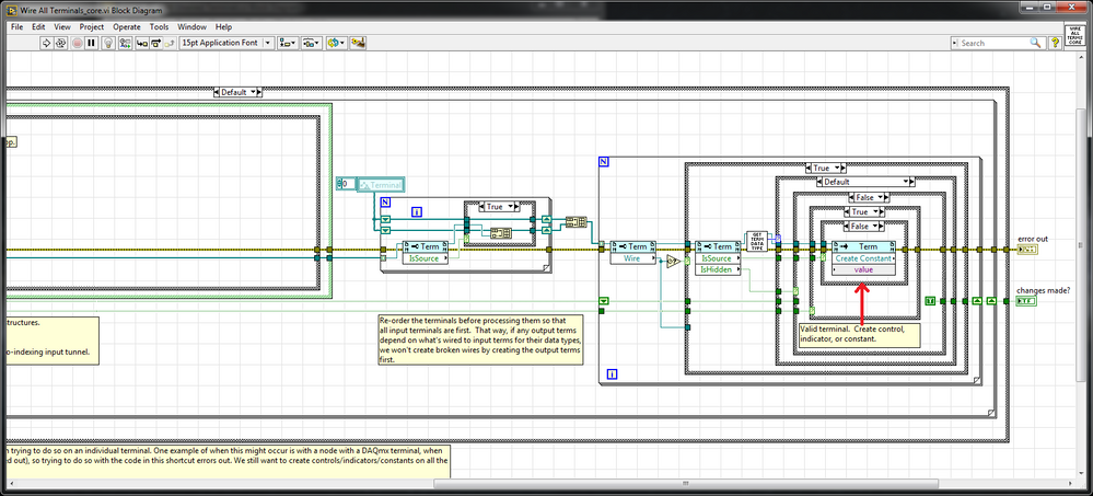
results in:
With the help of the 'constant to create' (which is something else altogether) works very well with the table control (of course, the constant is not connected to the Terminal in this case).
Tested in LV 2016 64 bit on Windows 7
You can change the functionality of the right click plugin by opening the Terminals_core.vi all the wires in the .llb following and by removing the structure of matter on the image below (keep remove it just method the structure around him). He did what you wanted in the original post, but is not very useful when you start to use it on items with multiple terminals (especially multiple output terminals). The code makes it seem quite expected, he travels all terminals it concludes and checks whether it is an input or output terminal. If it's an entry, it creates a constant, if it is an output, it does nothing. The change that I did just creates a constant whether it is an input or output.
time Board \resource\plugins\PopupMenus\edit and diagram\Wire all Terminals.llb Unwired -
Mixed Signal graphic = > line of bad names
Hello
I want to use a graph of Mixed Signal and I noticed that the digital waveforms line names are not properly displayed.
For example:
The attributes of the wave the nams of line are defined as "Name1" "Name2"; "Name3"...
On the graph of Mixed Signal, the first line is correctly called 'Name1' but all the others are called "Digital 1-> Line 0"; ' " Digital 2-> line 0 '...
Is this a bug in LabView?
If you use a normal digital chart, all names are displayed correctly.
Yes, I know that I can change the linenames with a property node, but it should also work with the attributes of waveform.
And a small second question: why are there no digital and mixed-signal graphics cards? I always build them manually...
Best regards
Reinhard
Hello Reinhard,
I think I found a link that might cover your problem. Looks like it has been known for some time
How can I assign names to my digital waveform shown mixed graphic Signal?
http://digital.NI.com/public.nsf/allkb/A6D74595D0EEFA6386257D77006537DE?OpenDocument
Best regards
Michael
-
Wiring of connectors in LabVIEW 2011 problems
I've just been 'bitten again"by a wiring problem with a connector for a VI in LabVIEW 2011 (I've not seen this behavior in any previous version of LabVIEW to 7.0).
The question is this. I (or one of my colleagues, who also noted it), run LabVIEW 2011 (August 2011 release), 32 - bit, Windows 7, 64-bit systems. I have create a VI using the usual 4-2-2-4 connector of mires and connect the appropriate connector. I save the VI, then drop it on a block diagram to use.
In another variation of this problem, the VI has fallen don't watch any connector or, if used to 'replace' an existing wired in VI with the same model of connector, "break" all the sons (because it has no connector when dropped on the diagram). Reopen and reconsider the VI show that, indeed, the connectors are wired, but when I use the VI, the connector wiring is absent (the VI dropped watch without connectors).
In the second variant, all right, the connectors appear as expected. But I then decide to move a connector. I have open the VI to edit, make a cut of this Terminal and rewire to its new location. The connector pane presents the new model. But when I drop the VI on a block diagram, the connector is in its original location.
Restart LabVIEW, indeed restart the PC, does not change. The only way to 'fix' this is to disconnect all terminals and a reconnect them. A nuisance, to say the least, but also an obvious bug.
Has anyone else seen elsewhere? I sent to OR, but it would be useful to know 'is it just me?' or not. In my defense, I've seen this problem on several computers, all win 7/LabVIEW 2011. I've also seen this with several LabVIEW projects.
I've attached a file with such a VI "buggy". When you open it, you will see that the 'Length' indicator is wired to the top of the connector set page. When I drop this VI on a new VI, however, the connector indicates coming out from the bottom!
BS
I was told by an engineer NOR that this problem (a) is real and (b) has been fixed in SP1 release (spring) 2011 LabVIEW. I have not had a chance to check this point, but (the trusting soul that I am), I consider that this problem has been a "Bug in LabVIEW 2011 that has been fixed in the SP1 Release"and therefore, I am prepared to mark this "resolved".
-
Bug of output conditional Boolean autoindexing
It's a little subtle, so I apologize in advance for the possible confusion.
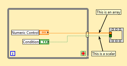
Start with a While loop and conditionally autoindex a scalar:
Example 1
As noted, the Boolean result is a scalar.
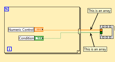
Now try the same thing with a loop (DO NOT REPLACE THE WHILE LOOP above by a For CREATING a BRAND NEW LOOP FOR loop):
Example 2
OK, so now the Boolean result is a table. Cool, that's what I wanted with the While loop above, but could not achieve.
Now you can play with replacements:
In example 1 above, replace the While loop with a loop For. Here's what you get:
If you CAN produce a Boolean scalar value in a loop For, but you have to go through a While loop to get it.
Now replace the loop in example 2 by a while loop:
All right, here's my table Boolean output. But I had to go through a While loop to do.
I'd say it's a bug, and the Boolean result of conditional indexation should be a table (not sure if there would be any how to have it be a scalar; last exit value?).
Tested by LavBIEW 2013 SP1 64 bit
Sam is correct: the conditional Terminal is not out of the loop for. When you "dragged through" the sequence you actually create an output of indexation of array of Booleans (unconditionally). Click on "cleaning chart" and you will see this. (I guess it might be a bug that LabView allows two nodes to overlay on the same place in the loop).
Moreover, you can always get a scalar to a loop for. right click on the tunnel, set it to "last".
Maybe you are looking for
-
Can I activate the Apple logo lit on the back of my 30 inch Apple display?
Can I activate the Apple logo lit on the back of my 30 inch Apple display? It would be cool to see!
-
Parent lock does not remove on the release 25
With the new update, Version 25, the Parent.Lock file does not during the release of Firefox. This problem never happened before. I use Windows 7 Home 64 bit on a gateway SX2800. When Parent.Lock precipitates, Firefox opens normally but if closed, th
-
I can't get firefox to respond - even to open. I tried the suggestion of support for the creation of a new profile, but the instructions are not working anymore so I can't create a new profile and test the system. I don't want to lose my info saved t
-
What happened to the MP3 option create?
Trying to put music on my wifes Mp3 player (not Apple) and the ability to create an mp3 version appears to have been deleted. Any ideas?
-
I've updated windows 8 (which was delivered with the laptop) to windows 8.1. I've also updated windows later. and with HP support assistant updated all the drivers, I have now version 2012.7.1231.2013 date: 13/01/2014 but still the problem frequently