Waveform graphic multiplot
Hello
I'm working on a project to map speed and rpm of a vehicle over time on axis x. I have sucessfully maped on an XY graph with speed on the right side and rpm on the left. Now, I want to change this representation in a stacked structure, but only with the help of a xy chart chart... I have. e using the same x-axis... and consider a range of woth speed rpm and 250 a range of 8500... then the graph must have 0-250 on the y-axis and the just above the 250 mrgin wide should start again from 0 up to 8500... is it possible...?
If Yes... Please help me. I'm working on LabView 7.1 and I have access to labview 2011 also.
Thank you
Rémy
Sorry about that, I forgot that the ILO.
Please read this: http://digital.ni.com/public.nsf/allkb/049C7E362BE4270A8625756E005CC46F
If this isn't what you're looking for, take a look at this: http://forums.ni.com/t5/LabVIEW/multiple-y-axis-with-different-scale-on-a-xy-graph/m-p/1731336?requi...
Tags: NI Software
Similar Questions
-
Graphic multiplot XY: bug in LabVIEW?
I started a chart XY simple concession with this array of points, a point being a cluster that contains an x value and a value of y. It worked fine until I wanted to a multiplot XY Chart.
According to the detailed help of the XY graph, it must accept an array of clusters of plots, where a parcel is an array of points. A point is a cluster that contains an x value and a value of y.
Everything what I try, it does not work. I've included this example where I got a cut wire.
The example also shows the other option to display the graph XY multiplot and it works but then I have to redo a lot of coding.
Thanks for helping me!
I found the solution and as a thank you for the attention, please find two ways to display multiplots on the XY graph.
-
How do I display two signals graphic multiplot
Hi, I am currently working on a LabVIEW program that requires me to display two signals measured by two current using MyRIO sensors OR. I am facing problems displaying two signals on dashboard of data, I know how and what should I log in the block diagram Front Panel of LabVIEW so that both signals, measured by the current sensors can be displayed on the dashboard of data?
-Introduction to LabVIEW: http://www.ni.com/getting-started/labview-basics/ and http://www.learnni.com/
-Check the labview\examples\general\graphs\charts.llb for examples of the waveform card: https://zone.ni.com/reference/en-XX/help/371361J-01/lvconcepts/types_of_graphs_and_charts/
-Examples: http://digital.ni.com/public.nsf/allkb/21E8163F259DA2058625703B007511AA , https://decibel.ni.com/content/docs/DOC-40940 , and https://decibel.ni.com/content/docs/DOC-5574 -
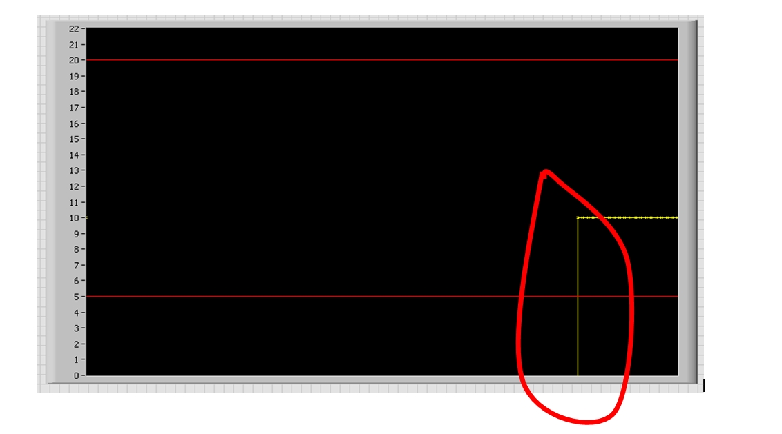
Change the Type of Interpolation of waveform graphic part
Hello dear colleagues,
How can I change the type of interpolation to a graph of waveform in part? Check the attached photo.
I don't want yellow interpolation to the beginning of the measure.
I know that the interpolation can be modified with the property node, but this has an influence on all points.
Any idea?
Thank you very much.
Hi maximint,
-NaN values used to hide unwanted in the plot points
-use separate plots when you do not want the "edges" in land line
-
continuous performance counter data
Hi all
I need assistance in the collection of data from a counter entry. I have a flow sensor that creates an output up to 600 Hz. frequency I plugged on the entry of a counter on my DAQ hardware, and in Labview, I plugged the DAQ assistant to a curve of waveform in a while loop. When I run it, it runs until it is among the samples and then gives the error 200284 and then shows the frequency over time on the chart.
However, I would like to see the frequency over time in real time on the chart, while it is running, and I would also like to run continuously until I hit the stop button. Can someone explain how this is done?
Best regards
Allard
Allard,
you stop the acquisition in the loop. This is why buy you a single package (of 1000 samples) and finish the acquisition. After that, the loop runs immediately create 100% CPU load on a carrot and basically doing nothing except waiting for the stop button to be pressed.
Learn more about the shift registers to store job and put the task to stop outside the loop. In the loop, modify the terminal to stop the loop itself to stop if the stop button has been pressed OR if an error in the acquisition took place.
Your current implementation will wait 1000 samples and display in the chart. The next update will completely replace the old conspiracy. According to the speed, you will get this behavior (@600 Hz about once every 2 seconds). You can do the following:
- Reduce the number of samples for example 100
- Use a graphic instead of waveform graphic waveform (for 'history')
or
- Set up a ring buffer using a shift register to update a chart similar to a graphic waveform
Norbert
-
DAQmx create several channels of
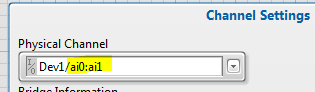
I downloaded the program entry OR bridge-continues and tries to modify it slightly to allow several Wheatstone bridges to connect. Currently, it has the ability to connect to a single channel but don't not to acquire information from several channels simultaneously. All information regarding the shunt calibration, bridge information and waveform graphic output remains the same. Ideally, the program displays the greatest value in the final waveform graph, but it is fine if it shows separate graphs for each of the two entrances. I was playing with it without much luck though if I start from scratch and you use the DAQ assistant, I'm able to get information without penalty. Any help would be appreciated.
In fact you are 99.99% of the way.
You just need to 4 characters
The name filtering on this control is even properly defined to allow multiple selections and just shift click on the second channel

-
customize multiple scales of Y in a wave chart
Hello
I'm showing two channels in the same form of wave, but with scales graph Y distinct. And I want to customize the two scales Y independently using nodes property. But I found under the node property of waveform graphic, there is only a single scale of Y.
Does anyone have the experience to customize them independently using nodes of property?
Thank you
XP\LabVIEW 2011
Use the "Active Y scale" property to select the scale you want to act accordingly.
Scale Y Active value of 0 (the first scale of Y), then set all the properties that you want for that 1 scalethen Y Y Active set at the scale of 1 (the second level Y) and again to set all the properties that you want for this 2nd scale Y.
Hope this helps
-
What is the problem with my vi?
Can someone tell me why I get the following error? "Error-200279 took place in DAQmx Read (analog 1-d Wfm NChan NSamp) .vi:2"
It runs for a few moments and then shows me the above. I have attached my vi. I use a box NI USB-6009 to read signals from my sensors and then to control my Velmex VXM (stepper motor controller). However, the DAQ Assistant keeps giving me issues.
Also, I'm using LabVIEW 9 if that makes a difference.
Thanks in advance!
Put a timer in milliseconds in the loop and get to a shift register. Subtract the new value of the value coming from the shift register and post it in an indicator. Perhaps also a waveform graphic as well. That will tell you how many milliseconds takes each iteration of the loop.
My guess is that it takes longer than 100 milliseconds. Since you are only entering 100 samples of data on each iteration of the loop (at the rate of 1000 Hz), you complete eventually your DAQ buffer.
-
A multi-terrain grah, which has a buffer and you can scroll back
Could someone help me, I'm doing a chart that can handle more than 1 field and updates in real time, has a buffer and allows to scroll back so that it runs without the cursor of the x axis back flip to the prior of the x-axis when you release the mouse.
I'm ok with aid graphic of waveform or waveform graph.
Waveform table almost it! It is so close, it has a buffer, it will update in real time and it can manage more than 1 field... but whenever I scroll to see previous data, once I have let go of the mouse button, the cursor changes beforehand... can not to analyze my data like this (and stopping the graph is not an option).
I was able to set up graphic waveform with a buffer, the credit goes to chilly
 charly from this forum for this solution... which was also so close, but I was not able to chart more than a plot with this stamp...
I enclose the waveform graphic solution that works almost... except no multiple locations. There are also under screw function... which is fine if that's what it takes, I thought that there could be a simpler solution... the waveform is so close.
Thank you very much!
-
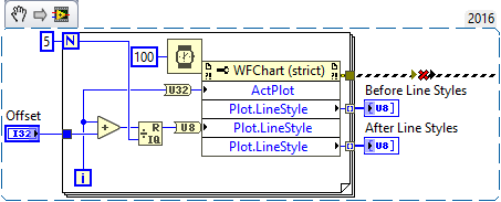
Graphical waveform Linestyle Bug?
Hello
I found that problems associated with the waveform diagrams and line styles in LV2016. If I change the line style of a multiplot for long dotted graph, the plot is changed for long dashed, but if new values are added, they will appear as short rushed. If there are other long plots dashed, they are modified short wiped out too. It happens with all styles (modern, classic, silver).
Everyone knows about these problems? Try again with the example below.
Niklas
The good news is that you are not crazy, LabVIEW 2016 's erratic behavior. In an attempt to discover what had happened and who was responsible, I wrote a little routine to read and set the Styles of plot line for graphic signals 2 consecutive values from 0 to 4 with a variable delay (so I could put 0, 1, 2, 3, 4, or, say, 2, 3, 4, 0, 1).
My initial code read the line Style, and then return. I could tell by looking at the plot that something wasn't right, and if I ran it again, I could see what values were used. For example, if I put 0, 1, 2, 3, 4, I had 0, 2, 2, 3, 4, while 1, 2, 3, 4, 0 gave me 2, 2, 3, 4, 0. Since I did the reading before writing it, I needed to run the code twice to see what did the writing, so I changed the code to read, write, read, as shown below:
(The error shown above, dotted line was 'dug' NiklasN While loop to ensure that ran first).
Either incidentally, I added the delay time within the loop "just in case" LabVIEW need time to "adjust" the plots - I think it is probably indifferent...
To my surprise, the line Styles after were exactly what I expected - with an offset of 0, 0, 1, 2, 3, 4. However, if I immediately revived this code, the front line Styles (which should have been 0, 1, 2, 3, 4) were now 0, 2, 2, 3, 4, false! Also, if you look at the plots when you run the program several times without change to the Offset, you see Plot 1 change the appearance (probably when my 'put' loop runs) and then switch again as the numbers start to come there.
I just called Tech Support, made to this post, attached the code illustrating the problem (so they will have something to test), and I expect that they will confirm the Bug and drop off a CAR (report on the Corrective Action) to solve this problem. Thank you, NiklasN, to describe this issue.
Bob Schor
-
The graphic evolution of waveform details updated?
Hi all, hope everyone is having a wonderful July 4.
-Very well, so I'm new to labview and find my things around simple things well enough, but not having never taken an interest programming, Im a little behind in the logic of the machine, so I thought I would ask here.
EDIT: using labview 2009. Vision package
The research that I do is to analyze the electron Speckle Pattern Interferometry (ESPI) images and their fringes to observe weaknesses points/potential fracture in different materials and others. I made a simple VI which allows me to draw a line on the image the ESPI and exit of the intensity of the light to a waveform chart to make it easier to objectively determine the size of the area (area where the fracture is more likely to occur) plastic.
What I would like is to be able to draw or first set the coordinates of the line, then somehow, be able to move vertically - using just my mouse or a digital controller - and have the graphic waveform updated in real time, as I do.
Any suggestions? Ive attatched my programs, one called "line.vi" uses digital input to determine the coordinates of the line.
Also, since I did not sem to be able to set the bitmap images, Ive uploaded a sample of image here http://img594.imageshack.us/img594/3566/espiimage.png I don't know why imageshack converted into a PNG image if
Thank you all

Hi itschad,
have you read the context-sensitive help for the chart? Here we show what kind of data you connect to draw more than one line on the graph of some...
"Does a weird issue where once I select the line, the intensity profile keeps itself adding time and time again on the end of the table, so a table that could have initially 100 datapoints, stop of is longer and longer."
That's how cards work. They keep a story (that you disable constantly). You can set the size of the history buffer. If the default value of 1024 points, it's too much for you, you can cut it to 100 - it is just a right click away... Otherwise, you must use a graph as a graph plots only the points that are currently wired to him (it does not keep a history of previous values).
-
How display the waveform acquired DAQ card separately in wavefrom graphic
I NI 9239 DAQ card and it has four channels. I need to create a user interface graphic labview in which I need to display all the forms of four wave separately. If I select all four channels of the daq assistant and connect the waveform table all four waves are coming to overlap... I need separately for the treatment... what should I do?
Thank you and best regards...
Try this
-
Updated graphical waveform constantly with digital I/o
I'm new to Labview and I try a digital waveforms graph to update in real time after the analysis of the data of a digital acquisition of data from input to output. Is this possible or real time update can only be done with graphics?
Hello
Once, a very similar subject has been addressed in the forum of LabVIEW, where DFGray has responded to the following:
- You can use an XY graph generating X values yourself. This will ensure that you place the data exactly where you want it on the X axis. It's fast, but involves a cost of memory.
- You can use a chart of waveform with an entry of waveform instead of the cluster that you are using. Use the antiderivative of waveform to build instead of the bundler to make your waveform. Set the values of t0 on the appropriate values (negative work, as do the numbers - time is in seconds, using the primitive of timestamp to convert to DBL timestamp). Finally, you must set the graph of waveform to use the t0 values. Pop - up on the waveform graph and make sure that ignore the time information is not checked. Depending on your version of LabVIEW, you may need to appear on the chart or axis. When you uncheck ignore timestamp, you'll probably want to reformat the x-axis again. Waveform graph clears the data at each iteration, so you have to replot all your data every time. Just create an array of waveforms and keep to add. The t0s will waveforms in the right places. Yes, this can cause memory problems.
- Finally, you can use the waveform, that memory. Create waveforms as you did for the waveform chart and send them to the chart. He remembered what was sent to her from run to run. Make sure to set the length of the graphic history (pop up on the chart and select chart history length...) long enough to contain your data together. You can use a node property to retrieve the data at the end, if you wish.
Link to the original thread: http://forums.ni.com/ni/board/message?board.id=170&requireLogin=False&thread.id=102699
I hope that this solution solves the problem.
-
Hello
I have a request I'm two signals to measure voltage in and feeding these signals to the mask and limit test VI to check if the signals are at your fingertips.
I want to have 1000 samples7sec (1 kHz sampling frequency). The software works well but the only problem is with graphical waveform updated. If I run the loop of producer with 1 ms, in the log file, I have 1000 samples/s, BUT I see nothing on the waveform table (the second graph on GUI). I mean, I do not see the tolerances and my i / p signal.
When I run the loop of producer with 2 ms, I can see signals on form of wave, but in the log file table, I have 500 or lower than that of the samples/s. I tried to change the rate of smapling but without success.
Any help would be appreciated.
see the attached example VI
1. with a continuous sampling, you do not want to set the size of buffer. Just let him be the default (which is quite large).
2. you really do not want a waiting in your loop of producer. Instead, you must inform the DAQmx Read to read something like 100 samples. Waiting for the upcoming data will limit your loop rates.
3. your second table is actually a chart. A graph has the whole story and shows exactly what you gave him changed. So, if you were trying to get all of the samples every 1ms when you are sampling at 1 kHz, you get 1 sample buffer playing and only 1 sample will be on the chart, making it appear as there is nothing in the graph. When you go to 2ms, you get 2 samples to appear on the chart. So I think you want to replace it with a chart.
-
Graphical waveform reference conflict with table 2D?
Hello world
I have a problem (I hope so easy?) with the joint 2.vi Untiltted... I need to wire a reference (with the chart "MVC and Stim") to the Sub - VI X axis Curs table under so I get the x-axis positions the cursor over the chart MVC and Stim... When this chart is a 1 d array, it works fine (graph at the bottom should graphic data between the sliders)... But I change the MVC and graphic stem in a 2D array that draws multiple waveforms graph Ref do not connect to the Subvi?
Any suggestions? I'm on a tight schedule, and it's killing me slowly...
Kind regards
Jack
Hello
I do not have chekced your screws I did not LabVIEW on my pc at the moment. I hope that the code is LV 2010 or below. If this isn't the case, please send the code in a version compatible with LV 2010.
However, a few questions:
What is your Ref entry selected to include the data type? You create the reference control once again inside your sub vi when you changed from 1 d in table 2D graphics?
If Yes, suggest to the two qus, try removing the data type "include". This can cause problems in the future. Otherwise, you must re-create your sub vi entry ref control again.
one way is, just transfer the reference on the front of the vi that has graphics for the sub vi, use application of the nodes to get the name of the control and the reference in the Panel, check your "MVC" and "Stim" among the control names, get the control reference. This will save you the dotted arrows.
Maybe you are looking for
-
Satellite L755-11J battery low charge question
I have a laptop Toshiba Satellite L755-11J for nearly three years. It is now stated the battery down and to replace. What is the average time that the battery lasts? Understand that they take some time, but seems a little earlier. Looking for a repla
-
hp f4440 deskjet scanner not working not not with mac osx 10.7.4
Hello; I have connected the hp deskjet f4440 on my Mac Pro computer Processor 2 x 2.8 GHz Quad - Core Intel Xeon Memory 8 GB 800 MHz DDR2 FB-DIMM Graphics ATI Radeon HD 2600 XT 256 MB Software Mac OS X Lion 10.7.4 (11E53) I went through all the tro
-
Wi - Fi calling will remain active on the iPhone 6 s
I'm having a lot of trouble getting my iPhone AT & T 6 s to work reliably with Wi - Fi calling. I have an unlimited data plan 1 original iPhone, which means that I have an old regime excluded with only 450 minutes of voice calls. Now, my dad just got
-
For the last month or so my shortcut keys f6 - f16 (the actions not the real f-keys) have stopped working. This includes the button wifi, microphone and toggle the webcame and the brightness setting. With the help of software I can see the real f key
-
Restore to the factory via HP Support Assistant settings?
I restore my laptop HP G62-b33EE to the original because of some problems with OS settings. It was delivered with Windows 7 Home Basic Edition but I upgraded to Ultimate and now I want to restore it since its performance is much reduced. What should