How do automate you a pwm signal?
I think I should do exactly what this guy:
http://forums.NI.com/T5/LabVIEW/dynamic-duty-cycle-change-for-PWM/m-p/2360002/highlight/true#M735803
Except that I don't have vague sinosoidal, pulse train is fine.
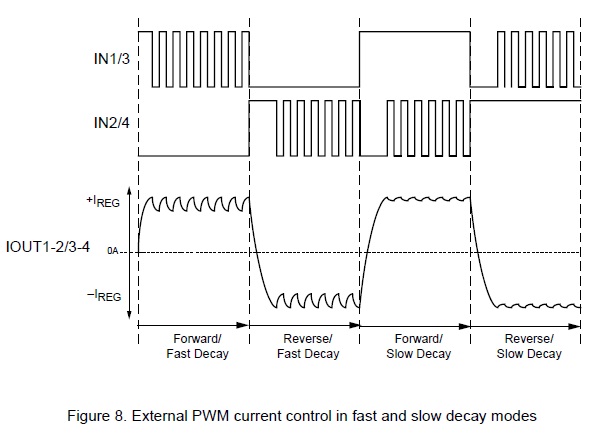
I need automation because I have to generate a pulse train resembling 1,2,3,4 below entries:
so that the output is generated in the osciloscope.
In fact, my question is how can you automate change the market factor after, say, milliseconds "x"?
In case anyone is curious, I use Figure 8 of this MSDS
How accurate do you need time to be? If you just want to adjust the signal after approximately 10 seconds, then it's easy. Put in a synchronization code that counts 10 s and change the value when the timer expires. You could store a range of values in a table and the index using their sequence, or just increment/decrement the duty cycle and frequency whenever the expiration of the timer, depending on what you need. The easiest way to do this is the function of 'Elapsed Time' (I'm not usually screw Express fan, but in this case, it's easy).
There is no time scale in your Figure 8, and your original message says that you need to change the use after a certain number of milliseconds. It's very different to change after a certain number of seconds, because to get milliseconds precise you need hardware timing, so that you can get seconds around the software.
Tags: NI Software
Similar Questions
-
Hi guys!
I'm working on a project where I want to control a motor dc with VirtualBench and LabView.
I have the engine connected to a H-Bridge motor, so I need to send 3 digital signals from the DIO VirtualBench to H-bridge.
With respect to management, I figured out, but now I need help to get a PWM signal to one of the DIO pins.
I can generate a PWM of the FGEN but do not know how to export to a DIO PIN.
I can also generate a PWM with the Express-> entry-> function Generate signal in Labview. But I get an error when you try to write this signal to pin.
Or is there a way smarter or easier?
Help, please!
/ Christian
The digital i/o pins are supported as the SPI, I2C, static DIO (timed by the software) and exports of MSO Trigger or FGEN signals start. There isn't any feature PWM/meter.
It is not a way to generate a PWM signal real on the DIO pins, nor can you give a digital waveform to dig write. From the FGEN might be your best option here.
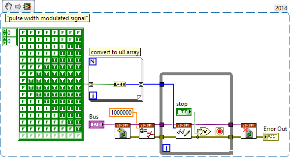
Another possibility might be to use (ab) the functionality of mastering of SPI. The following VI generates a modulated signal of pulse on dig/1 (MOSI) width. It will also generate signals on dig/0 (CLK) and dig/3 (CS), which may not be desirable, and you will have "gaps" between each call to read write of SPI.
-
How do I output a digital signal to an analog signal
Hi all, I use a PCI 6221 with LabVIEW 2010 (no add-on) with the CB-68LPR connection block and I want to use an input signal analog of voltage of between 0 V and 5 V of an LDR to change the brightness of an LED, so I can maintain a stable lighting for a webcam capture feature level image and treatment system.
I can get the analog input voltage of the LDR (set up as a voltage divider circuit) using the DAQ assistant, via the channel of Ain 0 on the use of pins 68 (AI.0), 67 (AI GND) and 14 (+ 5 V) and write it in a graphic and digital display but I don't know how to write the value to a PIN that can be used for PWM I think assistance from pine 40 PFI 13 P2.5 and a digital (GND pin 13).
I looked at the example of code that was written to produce a PWM signal, but these programs don't signal to a device/circuit, they are just "nothing stuff" that the PWM signal to a graph.
Can someone help me or direct me to tutorials/code examples which are of real-world applications?
Hello
PWM can be done in DAQmx using a task of the meter output.
I think that example 'PWM-Counter Output.vi' goes quite a long way to do want you want I think. It is located in the LabVIEW examples of shipping.
I also found here:
http://zone.NI.com/DevZone/CDA/EPD/p/ID/1710
This could be useful a read thus:
http://zone.NI.com/DevZone/CDA/tut/p/ID/2991
Let me know if it's of any help.
-
Generate PWM signals with 1.5 ms pulse width
Hi all
I'm working on a project where I need to generate a PWM with a pulse between 1.3 and 1.7 width ms to order a servo rotation continues. LabView is in communication with an arduino Uno microcontroller by LINX. My original plan was to use the milliseconds of wait function in LabVIew to do this. I put the PIN PWM high, wait 1.3 or 1.4 ms then set the low axis for 20 less ms pulsewidth. before repeating. This is how I have gnereate one using the Arduino IDE pulse width, so I thought I'd be able to do something similar here. However, as I'm sure is already obvious to anyone who reads this, the milliseconds waiting finction in LabView only accepts the whole entries. Arduino IDE is similar, but there is a delayMicrosecond function that can be used, so if I want 1.4 ms I use 1400 US snf then convert it in ms for the 20 least part. How can I do something similar in LabView? Also. When I run the program as what with a 1 ms pulsewidth I have a strange behavior. It in fact generates a PWM signal, somewhere between 0.75 and 1.25 ms and with a period between 50 and 54 ms, it turns into a model each about half a second. I'm using LabView 2014. Any ideas?
Chris
You can't get that kind of resolution with Windows and any delay you specify will have considerable jitter due to Windows. If you can pass values with Linx and allows the arduino to control them, stick with that.
-
Why are there at - it such a delay, write and read a PWM signal to digital input?
Hello! I am trying to read and take action on a PWM signal. The equiptment I'll have access to: 9201, 9425 and cDAQ-9172 chassis of NOR.
That's kind of what I'm experimenting with now (I have tested with a device USB 6211). Someone at - it a better idea how to do that?
The problems that I encounter:
(1) it seems there be then buffering of questions?
(2) it takes too long.
My vi is attached.
Thanks in advance for any help you can give.
Also, in my final application, I will not have to create the PWM signal - this is just to test the acquisition currently.
Try to use functions DAQmx directly rather than the DAQ Assistant. They are a little more work to learn but are more effective. Your 6211 can generate a PWM signal in hardware, so use it (see examples of LabVIEW). Finally, of course there will be some delay in your code. You read to 1.5 k samples to 1 k/second, so each loop cycle will be 1.5 s.
EDIT: also, why you write 1 k samples and then read 1.5 k, both 1 k per second? This means that your output will not generate any signal for long periods of time...
-
How can I respond to the signals of the QML context properties?
I put a property will involve on my .cpp, so I can access it on my document QML.
How I respond to the signals defined in this context property class?
Hello
You can connect signals to help
contextName.signalName.connect (javascriptFunction);
to disconnect:
contextName.signalName.disconnect (javascriptFunction);Or use the {} QtQuick connections for automatic connection / disconnection:
-
HP 3050 has J116g: How do install you a printer HP 3050 has J116g internet wireless
We have a wireless NETGEAR but not internet router.
I created one with the Internet several times without problem.
How do install you a range of printers HP 3050 has J116g as wireless internet?
Thank you!
Thank you for responding @tollymcc
The Netgear should disseminate its own signal, you should be able to view and connect to available wireless networks on your computer.
Please let me know if any of these steps has resolved your problem, or if there is anything else I can do to help.
I look forward to hear from you!
Thank you
-
generation of two complementary pwm signals using myrio
Hello, im working on a project and I need to generate two complementary pwm signals (when we go to 1, the other goes to 0) using myrio.
the problem with the blocks of myrio pwm is that when you set the market factor, the signal always starts with its high value. Can someone help me please?
Hello
You can create a Boolean square signal with chosen service and frequency cycle, create its opposite with makes NO sense and then send both signals via Digital Out vi (myRIO/Default/Digital Out) to two different outputs.
Best regards
-
I have a DAQ Assistant configured to read 2 channels at the same time. When I have a graphical indicator of wire to the output, I see 2 signals mixed together. How I divided them into separate signals?
When I wire any type of indicator, it is show that a release of a single channel.
I want 2 indicators showing 2 different signals as expected from 2 channels configured. How to do this?
I tried to use split signal but it end by showing that 1 out of 1 signal two indicators.
Thanks in advance.
Yes you are right. I tried, but I don't have the result.
I just find the path. When we launch the split signal, we should expand it (split signal icon) by top, not the bottom. It took me a while to understand this.
Thank you
-
How to automate the cutting through a visual basic 6.0 application tool?
Original title: Visual basic 6.0
How to automate the tool to cut through a visual basic 6.0 application. Or my visual basic 6.0 application is to take screenshots and save them as gif images, but the files are too big and take a long time to be sent by e-mail in real time. Please if someone could help, need a code in visual basic 6.0 to make these small files.
Hello
You can get support for development on the MSDN Forums tools.
MSDN forums: Index
http://social.msdn.Microsoft.com/forums/en-us/categories
Concerning
-
Voltage offset problems with the NO-9401 for PWM signal output
I try to create a 20 kHz PWM signal to drive a motor control circuit uses the NI 9401 module in the chassis OR cRIO-9073. Generating the PWM signal works. For some reason, changes in shift of power as the market factor is increased. It is less effective for the engine, as you can imagine.
The code I am using is the finder of the example, for the generation of PWM on an FPGA and is attached.
I thought that it worked before but may have used the the NOR-9505 rather PWM output to test my circuit. It would be unreasonable for me to do this as a permanent solution.
The problem can be summed up as: with an increase in the liability of the cycle the voltage line (offset) movement of the output signal in the negative (according to ADGE) Basic or down. The Vpp signal is correct and does not change. Against ticks from 0 to the maximum of 2000 ticks (duty cycle IN), the offset voltage shift is such that 100% the level of full voltage is 0V.
Any ideas as to why this offset voltage shift that happens?
Do not be dismayed, I worked on the problem. There was a connection problem - I thought I was logged in as reference Earth, but it has not been properly clipped.
-
Problem when the PWM signal combinning and analog signal TOGETHER!
Hello everyone,
first I DAQmx 6212, and I need to run the water pump small (9V - 16V) that should be driven by a PWM signal; I also have a motor (5V - 13V) for a water supply which must be controlled by an analog signal and it has built in a force feedback potentiometer, I logged onto this potentiometer correction + 5V the DAQmx and used the output voltage of the third extremety as a value to diagnose to know the position of the engine.
My VI shows:
1 is a normal meter production to create my PWMout signal.
2 is an analog input, I use it as a PWMin to the LabVIEW to diagnose what is happenning in my pump water through the cycle and frequency.
3 is an entry of the third extremety of the analog potentiometer.
4 is an analog output that I used as power supply of the motor valve and I used an AC/DC amplifier for aplify signal the DAQmx and the motor road, between the two (3. 4.) I made a comeback with a few calculations, I had a P-controller to know the real position of the engine valve.
My problem:
When setting to 1. and 2. in the same VI only, I get an own PWM output with no problem.
also with 3. and 4. in the same VI only i can control the motor valve without any problem.
but when I put all these 4 set found in the attached VI, I have a problem as the engine valve turn continuously without stopping even if I change the position of the valve between 0 and 100%, I should mention that I see a PWM normal outside a signal on my oscilloscope, another thing to delete one of (1 or 2) and run the engine valve VI works fine without any problems.
so this my problem, if you can think of any solution please let me know.
Thanks in advance for your help.
Kind regards
Caliente
Here's your VI, slightly modified so the two analog inputs belong to the same task. This if only for purposes of illustration, I him have not tested. You will still need to do some debugging.
While changing your VI, I noticed another potential problem with your original configuration. You have configured the two tasks of AI for the same frequency, but read you 10000 samples of one of them and only 100 samples from the other (and throw it most of it). Data acquisition data are buffered, and if you read as fast as you acquire, the buffer fills eventually. If you read 10,000 samples of a channel, and the other channel acquires at the same rate, then when you read from the second channel you will get old stale data or an error full buffer.
-
How can I generate modulated amplitude signal?
How can I generate modulated amplitude signal?
I got this VI examples NOR but in this VI "m message signal .vi is missing. So, how can I generate missing VI or VI full for the Amplitude modulation signal using 5441 PXI and PXI-5610 as upconvertor. If possible guide me steps to generate.
Thank you and best regards
Isabelle Kodgirwar
Graduate student
University of Texas at Arlington.
Hi Aron,
-
How to automate ScanDisk using Task Scheduler tool?
There is no file c:\windows\scandskw.exe on my XP, does anyone have any suggestions on how to automate using Task Scheduler tool in XP ScanDisk?
Thanks for all the suggestions
Saturday, August 14, 2010, 02:18:45 + 0000, SC Tom wrote:
There is no program Scandisk in Windows XP.
In order to specify that the person you are you answer to the. There is no program
called the Scandisk, but there is a program with this feature; There
Called Chkdsk.Ken Blake
-
How do access you the list of programs that start when you start your computer?
How do access you the list of programs that start when you start your computer?
Saturday, January 19, 2013 19:48:16 + 0000, Psylly wrote:
How do access you the list of programs that start when you start your computer?
First of all, note that you should be concerned all the programs
starts automatically, not only those who enter in the system tray.
Not all the programs auto-start manifesting by an icon in the
Status bar.On each program, you don't want to automatically start, check its
Options to see if he has the choice of not start (make sure you)
Indeed choose not to run, not just a "don't show icon.
Optional). Many can easily and better be arrested like that. If that is not
work, run MSCONFIG from the start. Run the line, and then click the Startup tab.
Uncheck the programs that you do not want to automatically start.However, if I were you, I wouldn't do it just for the application of
the minimum number of running programs. Despite what many people say
You should be concerned, not with the way that a lot of these programs
you run, but who. Some of them can degrade performance severely, but
others have no effect on performance.Don't stop all programs to run willy-nilly. What you need to do
is to determine what each program is, what its value is up to you which
the performance cost is its running all the time. You can try
Internet search and ask questions about the details here.Once you have this information, you can make a smart informed
decision on what you want to keep and what you want to get rid of.
Ken Blake, Microsoft MVP
Maybe you are looking for
-
Hi, after updating my firefox, I can't open the download icon
Today firefox updated the browser automatically. Then I download something after download of color of the icon should change to blue, but it is not. Yet gray. While I try to click on it, it will not open the download.Now, I have to manually open my d
-
After buying an opportunity 2012/13 Macbook Air I can access is the app store. I changed my password but still no luck. Message says it can't recognize my Macbook.
-
Mozilla crashes when you try to load the addresses of rss and xml
Whenever I try to load any stream rss or xml feed in the address bar (I tried four or five different ones), mozilla is trying to load the page, fails and then fails altogether. I tried to create a new profile to see if any existing modules or plugins
-
Need help: error communicating with the server on boot up
Anyone an idea what server it could be? I received this alert after starting my Mac Pro (OSX 10.7.5): He didn't identify which server, what app or anything like that. I wonder if I should do a virus check. If someone things can a good idea, it's been
-
HP Photosmart D5460: Impressions blue when it should be black printing on photo paper
First attempt to print from the update to Windows 10