http trigger
I'm trying to set up the following. A Web page, a user enters his phone number on a form, when the user clicks on send the url triggers a script and phone number is passed from the web page to a variable in the script
I followed the guide but don't know how to set the http page
any help would be great
If you want to use a form to collect user information or to the appellant, then you want to set up your web page as follows:
http://:8080/">
Name:
name = "visitor_name" size = "30" / >
Phone number:
name = "phone_number" size = "30" / >
value = "Send info" / >
In the part of the action of the form, you can call the trigger http that you have configured the CRS (IPCCx or IP IVR). is the name of the trigger on the CRS.
From here the associted file application and .aef with the trigger runs. "The step to READ CONTACT HTTP INFORMATION can then be used in the script .aef to extract the variables"visitor_name"& phone_number."
Tags: Cisco Support
Similar Questions
-
Hello
We have a requirement of click to call in installing 10.5 UCCX with customer website (user input) for our client, anyone who tested it in the laboratory/prod settings?
Thank you!!
MagaliHello magali.
It is possible to deploy with UCCX HTTP trigger type. To get the number of customer via the HTTP trigger to the script. Then we can place the outgoing number of customer to campaign or appeal directly to the customer and place this call to the QSC.
There are two scripts for web reminder in Cisco repository of scripts, see this http://www.cisco.com/c/dam/en/us/td/docs/voice_ip_comm/cust_contact/cont...
-
Java errors using ticket submit script.
Hello people.
I used the script submit_ticket.aef of your repository with success on the IPCCX 3.5.3sr2, 4.1.3sr1 CCM for several months now. The scripts have not been updated, but now we receive loads of java errors after we click on submit:
com.cisco.app.ApplicationTaskInactiveException: is no longer running for the task
com.cisco.wfapi.WFClassInvocationException: error call to the class.
java.lang.reflect.InvocationTargetException
to com.cisco.app.impl.ApplicationManagerImpl$ TaskImpl.cleanup (ApplicationManagerImpl.java:4063)
at com.cisco.app.impl.WFWorkflowAppDebugTaskWrapper.taskAborted(WFWorkflowAppDebugTaskWrapper.java:693)
at com.cisco.app.impl.WFWorkflowAppDebugTaskWrapper.execute(WFWorkflowAppDebugTaskWrapper.java:748)
at com.cisco.wfframework.engine.core.TaskManager.runTaskNormally(TaskManager.java:291)
at com.cisco.wfframework.engine.core.TaskManager.runTask(TaskManager.java:246)
at com.cisco.wfframework.engine.core.Invoker.invoke(Invoker.java:67)
The session ID is to be filled ok example: http://10.102.0.100:8080/ticket.jsp?%20&sessionID=1108000000007,0
When you click submit submit & no attached java error occurs.
When debugging the submit_ticket.aef script I get an error of class invocation. ; is:Java.lang.reflect.InvocationTargetException nested exception
Could someone please help me with how I find what mean these errors of java and what is perhaps the task no longer running.
Tips/advice etc would be greatly appreciated.
See you soon,.
NJ.
1. in the office administrator, according to the company, make sure you have
This two fields created: sessionID (type 2) sequence (type 3)
2. change the available to field (type 252) by selecting default in the page layout list.change the name, rather than default, the ticket name.
3 Add the sessionID and the succession to the field of page layout.
4. now, go in the Workflow in Desktop Admin: in the office administrator select Workflow.In events, select the (s) loose.
Add a rule called ticket and enter an action called ticketEntry.Select launch application external nd:
: May Explorer\IEXPLORE. EXE
Hover over the sessionID of the arguments column. Select Enable rule, any Condition is true, and a condition set sessionID is not empty.
Click OK.
5. go in the app and create submit_app. In the field script select submit_ticket.aef, and then add a HTTP trigger (/ ticket)
6 Creat a subsystem HTTP: URL: / ticket (please do not confuse this name with the ticket.jsp that is executed when the agent filed the appeal)
Language: EnglishApplication name: name of your choice (example Submit_app)
Please do not forget that you have followed all of these steps.
-
Display statistics of queue on a reader Board
We would like to display our status of queue in real-time which is calls how in the queue, aware of waiting on a reader Board etc? Anyone done this before and if so, how did you do?
Thank you.
Due to the number of requests, I'll just post this script. This script queries the current state of a specific agent agent then sends the data to a template xml file. Keep in mind you need to create an HTTP trigger to call this script.
-
How can I create a trigger e-mail messages sets a phone when Gets an email from particulry?
Hi team, support
Customer email thunderbird whit, how can I create a trigger e-mail messages rule a phone dial when comes a word of the body particularly E-mail?Kind regards
Alessandro.I don't think you can do this with ordinary Thunderbird. But this add-on
https://addons.Mozilla.org/en-us/Thunderbird/addon/FiltaQuilla/
allows you to run javascript or IIRC, launch an external program when a given filter condition is met. So this does not exactly provide an answer to your question, but allows a possible solution. '
-
Hello friends,
I have a question. I need to trigger an output of Myrio with a single pulse. After the pulse, the output will remain active. Then with another single pulse, the output will be switched off. Should what tool I use?
Thanks for listening,
Kind regards
David
Hi Davi08,
I did a little research for you answer and I found another "NI Discussion forums" forum that maybe can help you.
Try using this link, I think this will help you.http://forums.NI.com/T5/academic-hardware-products-Elvis/myRIO-digital-trigger/TD-p/3278560
Best regards
-
Mounted daqmx calendar/trigger on 2 chassis mxi-express
I have 2 chassis SMU (including one with a RT controller) connected with SMU-SMU/8384-8381-MXI-express boards.
I can see all the devices in both chassis and can configure DAQmx tasks in each chassis individually, but I can't create any single task with a device of two chassis. When there is a feature of two chassis in the task, I get:
Error-89125 occurred at DAQmx start Task.vi:7220002
No registered trigger could be found between the devices in the range... Make sure that there is a trigger line available on the bus triggering shared between devices.
Is this possible in the software? Or should I add material? I can't find any docs or examples on this subject, other than a promising article on Veristand (ni.com/white-paper/14637/en/, #2) but I can't implement in MAX or NV. Timing is not critical (50 to 100 ms is very good), I just need many devices on 2 sites, so the MXI solution seems to fit in. I thought the solution was to use the local clock on each chassis and set up a trigger shared/exported, but impossible to find something that works.
Thank you!
Hey brimcd,
You are right; It is not a way to send a trigger between chassis without timing card. This link goes into a bit more detail: http://digital.ni.com/public.nsf/allkb/D91582EBF0810F4486256E70004E4145
-
Problem of generation of Sync trigger in several synchronization USRP RIO 2943R problem
Generation problem shutter Sync in several synchronization USRP RIO 2943R problem.
Previous SR you may already know I'm stacked in USRP RIO multiple synchronization problem, especially in the mode based on the signal. Now I can cut down, the problem is mainly due to the outbreak of sync signals generation.
First of all, I read the article and the discussion in the following two links:
http://forums.NI.com/T5/USRP-software-radio/how-to-synchronize-multiple-USRP-Rio-294x-devices/TD-p/3...
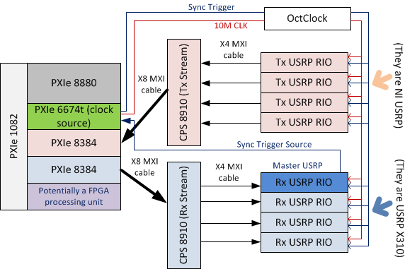
http://zone.NI.com/reference/en-XX/help/373380D-01/usrphelp/synchronization/and I did my connection of the material according to the suggestions in the second link. My system schematic is shown in the following image:
I checked OctColck and SMU 6674 T connections. They are all connected correctly and the cable are fine. I use the niUsrpRio200_XcvrSyncPps.lvbitx.
According to the description of documents and discussion forum, the USRP RIO 1st in the list of devices are considered to be the USRP Master. Then, the FPGA to master USRP RIO released "trigger of sync" signal through the 'PPS Trigger Out' SMA port in RIO USRP box.
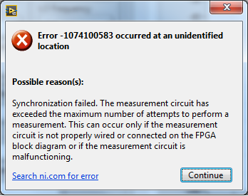
Based on the my analysis of the system, the first impression I have is the USRP Master does not export the 'sync trigger' correctly. The host VI reports the error like this:I was trying to measure the "synchronization trigger" using oscilloscope, but I found that it is impossible, because the host VI can not yet run, so there is that no signal can be seen from port 'PPS Trigger OUT.
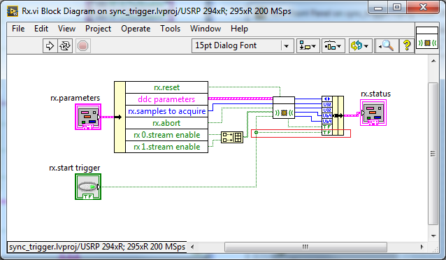
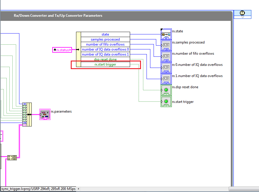
So I think that if I can watch this signal "sync trigger" in home VI by importing this signal from FPGA to host VI. I did some changes on the FPGA VI as shown in the following image to watch this signal of façade of the host VI. but not so successful. the rx.start tragger relaxation and tx.start do not appear on the host vi read/write control function.
-
Trying to send a software trigger to 5114
Greetings to all my friends on the set of the digitizer,
I try to send a software trigger to my digitizer 5114 in c# .NET. There is no cable attached to the Commission, there is no signal going. It works very well with the trigger set to "immediate". However, I would like to make a trigger of software I test things. It does not work - when I told FetchByte it crashes with a timeout.
Here's the basic gist of what I have in my code:
PrecisionTimeSpan triggerHoldoff = PrecisionTimeSpan.Zero;
PrecisionTimeSpan triggerDelay = PrecisionTimeSpan.Zero;
scopeSession.Trigger.ConfigureTriggerSoftware (triggerHoldoff, triggerDelay);
scopeSession.Measurement.Initiate ();
scopeSession.Trigger.AdvanceTrigger.SendSoftwareEdgeTrigger (); Is this good?
waveformByte = scopeSession.Channels [ChannelName]. Measurement.FetchByte (timeout, 1, waveformByte, out waveformInfo); This request times out.
This looks good, or is there another way to set up a trigger of generic software, and then send it to the 5114? Thanks for any thoughts.
Kind regards
Penny
Penny,
Thank you for using the API OR-SCOPE of .NET 2.0 so soon after the release!
In order to respond to your question as to why worked scopeSession.Trigger.ReferenceTrigger.SendSoftwareEdgeTrigger () and scopeSession.Trigger.AdvanceTrigger.SendSoftwareEdgeTrigger (); not be found in the help topics include file:
http://zone.NI.com/reference/en-XX/help/370592V-01/digitizers/5122_state_model/
Your code has expired because he was in a State of pre of sampling, waiting for the trigger for reference. Once the acquisition is completed, i.e. when (in yellow), he will wait for the trigger of the advance. The advance trigger is used for multiple acquisitions records and allows you to wait between records.
This table is also useful because it shows all events that can be exported and triggers that can be imported to your scanner. (and when these triggers can be used).
I hope that helps!
-Nathan
-
LabVIEW statechart module of data acquisition error external trigger
I have a 2 loop vi is the acquisition of data of a data acquisition instrument loop and the second is a loop to run my statechart of. I would like to respond to an error in device of acquisition data if it occurs in transition out of my current state in my diagram States-transitions and enable management of custom unique business mistakes. My States-transitions diagram is synchronous and send it external trigger.vi funciton will not work with it. How to achieve this? In addition, there is some confusion about this literature in http://zone.ni.com/reference/en-XX/help/372103F-01/lvscconcepts/sc_c_callervi/ at the bottom of the page it saidNote sending triggers for synchronous charts is optional. If you do send triggers, LabVIEW sends the NULL trigger for transitions. If you send a synchronous statechart triggers, you can send these triggers to the caller VI. »
Is it possible to do this and if so how with the synchronous statechart?
Thank you, it should work for me
-
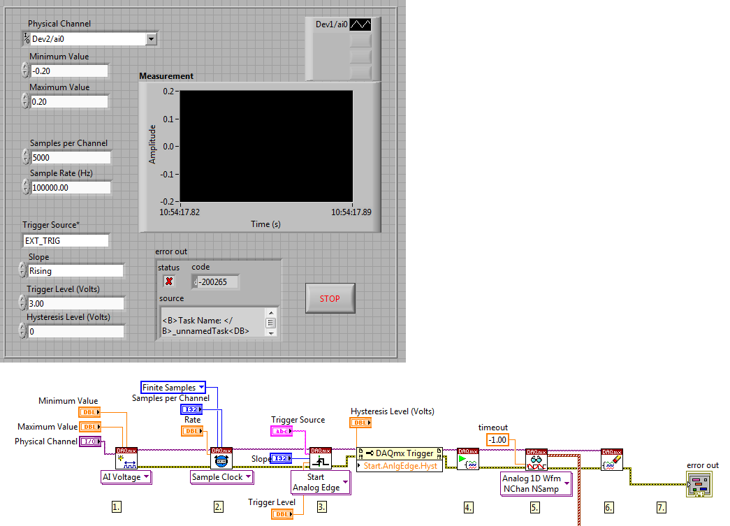
Source of external trigger PCI-4472
Dear all,
I have a PCI-4472 b I want to program to acquire a signal channel 0 whenever it recives a TTL signal throw the input external trigger.
I use a modified example but I don't know which is the name of the external trigger source. I always receive this type of error (for example if I connect to a string that contains "EXT_TRIG"):
Code: '-200265 '.
"DAQmx Start Task.vi:1 '.
Property: Start.AnlgEdge.Src
Value: EXT_TRIG" Task name: _unnamedTask
" The program I use is of this form:
First of all, this error means that I have no right external trigger source name entry?
If so, which one is the good name of the source of external trigger for NI4472B?
Thank you for the help
Hello
The error pops up because there is no channel named EXT TRIG. If you receive a trigger channel 0, I think that the best way is to specify the name of the channel in the "DAQmx Start Task. There is a terminal where you can specify the name of the channel and use that name to a string for the trigger input. I think this should solve the problem.
I referred to this knowledge base.
http://AE.natinst.com/public.nsf/webPreview/BEBB10D02D72798A8625736B0076B09A?OpenDocument
Also, looks like you have trigger 'start analog edge '. Since you want to get the TTL signal, why not try 'start digital dashboard' trigger?
Kind regards
-
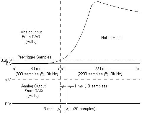
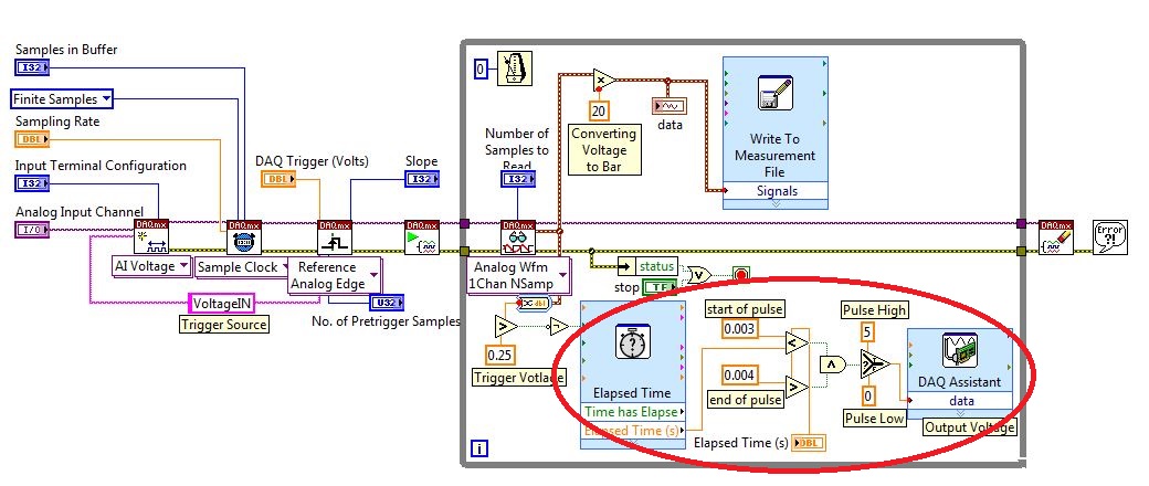
I am working with a combustion chamber and using a system of data acquisition (with the hardware OR SCB - 68) to read the pressure in the cylinder (such as analog voltage). I'm trying a pulse delayed, 1 millisecond to 5 volts of output once the pressure in the cylinder is high above 5 bar (which corresponds to an analogue voltage of 0.25 V). I would also like to record 30 ms samples before the trigger and 220 ms samples after the outbreak. The following image shows visually what I'm talking about.
I created a LabVIEW VI (which is attached), but I keep running into 2 issues:
- When I run with samples finished after a period of time, I get error-200281which I don't quite understand.
- Using the Express VI 'Out of time' to keep time for the pulse I can not get a resolution of 1 millisecond, the pulse is not generated when I put the window between 0.003 and 0.004 seconds for high pulse (i.e. the resolution of 'Elapsed Time' seems to be too coarse).
I'm a beginner to LabVIEW sorry if my questions are trivial or my VI makes no sense, but I was stuck on this during more than a week. Any help would be greatly appreciated!
Thank you
Morgen
This isn't a good way to trigger a pulse.
Use a trigger DAQmx to send the pulse when your acquired signal exceeds 250 mV you specified.See this for DAQmx trigger:
-
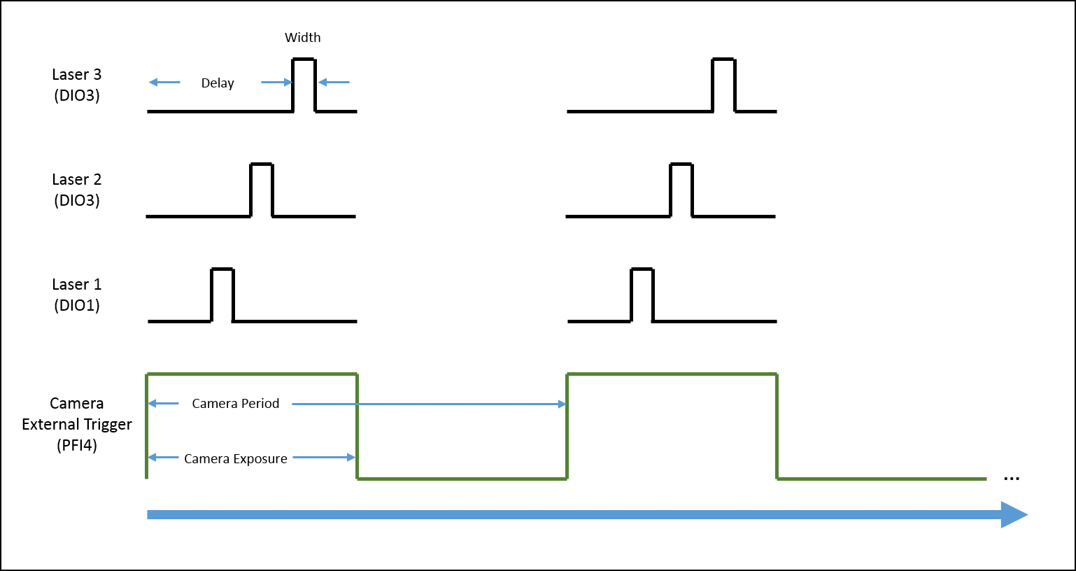
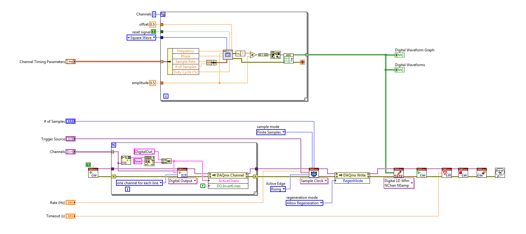
Generate a single pulse on several channels of an external trigger high-speed DIO
Hello
I'm trying to implement a system using a PCIe-6535 b connected to a high speed of SMB-2163 DIO. The system must be configured to work with a camera send a trigger (at the beginning of each show) to the PFI4 which in turn sends a single pulse on three digital output channels to lasers. Each output has its own specific deadline and the width. There is no counter on the SMB-2163, so I think I need to use Pulse Width Modulation (PWM). I saw this example and adapted to my system:
https://decibel.NI.com/content/docs/doc-8010
However, when the source to enter the DAQmx VI of sample clock is set to PFI4 (instead of the on-board clock) to receive input from the camera, changes in behaviour. The rate of sampling in the sample clock VI is ignored, and each element of the digital waveform is triggered. I need the sequence to complete each after trigger.
I am attaching a quick diagram of the sequence. Any suggestions on how I can get this kind of events triggered? (With the help of LabVIEW 2013)
Thank you
Mike
PLATES
The external signal must be configured as a trigger for digital startup rather than the sample clock. I do not think the 6535 redeclenchables supports digital output, so you don't have to restart the task after receipt of each trigger (something like this, however you can improve performance by committing to the task by using the task of control DAQmx before entering the loop).
Best regards
-
Hello colleagues LV coders.
I've looked everywhere and can't find the answer to the following question: How can I access a trigger in Star in a PXI 1031 DC chassis? I know this must be through SLOT2.
I currently have a micro controller PXI - 8102 SLOT1, an arbitrary generator (AWG) pxi-5422 the SLOT2 and a PXI-7954r FPGA with a digitizer 5761 nor in SLOT4. I know that activitate the outbreak in Star, a "Timing and synchronization' card must be in the SLOT2. Is it possible that I can use either the microntroller in SLOT1 or the Working Group in the SLOT2 for access to the relaxation of Star? I think that the microcontroller will probably be able to reach, but what about the Working Group?
Follow-up on issues is as follows: suppose that I am able to implement this Star trigger correctly, once the working group receives the signal to send its chirp 10usec by having the Star trigger go HIGH, is there a way of simultaneously to adjust the line of PFI0 HIGH in the Working Group and a time that the 10usec is completely sent to set the PFI0 on the BASS line in the generator of signals for usec then 90? This could be repeated indefinitely and the PFI0 line is used to control a switch via a cable. In addition, this PFI0 of the GTS line will always be equal to "output mode".
Thanks in advance a ton. If I found the answer elsewhere, I'll make sure to update here.
-Daniel
The link "what GIS speeds. do my chassis PXI Trigger lines Support' really helped me to understand how triggers are connected in the bottom of the basket of the PXI chassis. In my case, I need my shutter button to get to the e in 1 usec and thus the PXI Trig. Bus to get there. No need to worry about the outbreak in Star for my application. Thanks for the research!
http://digital.NI.com/public.nsf/allkb/892204272FF2C0BE862575C500636AF6?OpenDocument
-Daniel
-
Group execute Trigger on 2 DMMs
Hello
I'm trying to use software trigger to trigger two Agilent 34401 DMM "simultaneously". I found this article from 2007:
However, the answer is less useful, because it does not address the issue.
What I'm trying to use is the function GPIB 488.2 Trigger List (such as recommended by NEITHER). However, generating a list by program turns out a touch... interesting.
Given that the selection of the device is made using aliases VISA, I am trying to use a property node to retrieve the GPIB address. As a temporary trial, I use a VI with the attached excerpt included code. With DMM configured in GPIB0::6:INSTR and GPIB0::22:INSTR (but try this at home with no real hardware attached), my probe shows all the values of property as 0.
I tried the wrong approach? Try this at the office with the DMM attached would produce a different result? (I'll try again tomorrow anyway.)
All comments would be appreciated.
Kind regards
Geoff
Try to work with the connected digital multimeters (and turned on), the primary address property returns exactly what I expect and the code snippet works - apparently - perfectly.
I had been struggling with getting the DMM to trigger and retrieve the measurements of the DMM. I tried to use the 'Trigger' function, but it doesn't seem to work without additional steps to ensure that the right listeners are selected - so the function "basic list". I also had problems of data recovery - partially because he was (probably) not trigger, but especially because I wasn't not wait long enough so that all samples must be collected.
For more information, this system has (by default, but configurable) 10 samples being played at intervals of 0.1 s, so you have to wait a second. I could just have increased the timeout, but it's a bit messy. Otherwise, I guess I could loop waiting for signals to be ready, but the driver for this DMM does not seem to include a query function.
The screw with a symbol of the timer on them simply contain a call to Wait (ms). It's cleaner (in my opinion) that put in a frame. Now that I have the work function, I also replaced the frame function timestamp and relaxation with a sub - VI.
Kind regards
Geoff
Maybe you are looking for
-
How can I connect if I forgot the answers to security questions?
I need to change my security questions, but I can't connect without the original responses to my questions...
-
HD/Fusion drive locked, it cannot erase or restore
I had difficulties with my drive stall at random for seemingly no reason. So, I did a full backup (not with Time Machine... which waived the slightest error) and intended to erase/recover and then reinstall. Well well, in the middle of the erase proc
-
Blue screen after installing SP3.
OK, I got a laptop the other day of a member of the family... was working fine when I got it I was behind on updates... so I downloaded and installed service pack 3 and when I restarted the laptop I get the blue screen... I tried to boot in safe mode
-
Whenever I have move photos from one folder to another file, the picture is no longer accessible.
I use Windows XP - perfectly up-to-date. Whenever I have move photos from one folder to another file, the picture is no longer available and cannot be removed with using unlocker. This has happened for several years. I copy pictures and new folder
-
Cannot open my saved Movie Maker!
I worked on a film for weeks, save that I will. Now, I try to open again to finish, and a box will appear indicating that another user is open on this computer. But it's not. How can I open it?