6033 PCI analog measurement noise
|
I want to assure you that I do everything I can to get the best measurement possible IM using a SCB-100; I use a card PCI 6033. I have connected my analog son Looking at a picture labeled e/s to 64 channel connector E series devices... I see to reason a choice AI GND, SENSE of HAVE it, HAVE SENSE 2, EXT REF, AO GND, D GND. I used the GND. HAVE My measure is close but there are a few milliamperes noise 4.30 should I get 4.80 on some units the extent of automation and I set up for single ref has ended and a 09:50 vdc extent I connected a wire to the GND AI for my units I measure power supply ground wire is short less than 10 inches, 16 gauge. I use the correct ground?. Thanks-Kurt |
Kurt,
Yes, it's good ground for a measurement of CSR. Is your source of signal floating or grounded? If it is connected to the Earth, I would recommend using differential or NRSE instead of CSR. Here is a document that is an excellent reference for wiring and noise considerations.
-Christina
Tags: NI Products
Similar Questions
-
With differential measurement noise problems
Hey everybody.
I use an NI USB-6211, LABView 2011 and Win7.
I'm trying to measure a voltage through a resistor using differential mode. But unfortunately im getting a lot of noise (on + - 25%).
The voltage source I use is variable and can go up to 600V. With my diet I am essentially heat a metal plate.
A parallel voltage divider is used to reduce the voltage by one hundredth (1 MOhm and 10 kOhm).
Two wires attached to the lower resistance then go directly into analog input 0 + 8 of data acquisition.
So if I'm trained 600V to the plate, data acquisition should get about 6V... and that's what I measure with my voltmeter attached to the acquisition of data input pins.
I also tried these resistances of POLARIZATION and connected the + and - leads to the analogous to the ground like a resistance I used 10 k, 100 k and 1 MOhm and 2 MOhm and
continue to receive a bad signal.
Two sketches of the wire as a signal (100V, supposed to measure 1V, no CORRECTION) are attached to the post.
Concerning
EDIT: I forgot to write that I even tried an another NI DAQ and still get this noise problem.
Also, I measured the voltage source signal using an oscilloscope and I see that noise. But the differential mode isn't supposed to
reduce noise to a minimum?
Hey everybody,
come to understand that the voltage divider resistors are medium to high and they were the main reason for the noise
problem.
Before I used 1 MOhm and 10 kOhm, now I use 100 ohm and 100 kOhm and with a median filter in this regard, it works very well!
But still, if I use the resistance of these BIASES they do not change.
Concerning
-
PCI-6733 signal noise when the computer screen is plugged, the weight on the case
Greetings,
I hope that it is in the right section.
Card: PCI-6733
I'm a 60 Hz, 2 mV peak-to-peak with a compensated 2.4mV noise when the monitor is plugged into the VGA port.
Same card in a second computer, problem is more serious, 4mV Ridge to Ridge, 4.3mV offset. When I push on the case near the power supply the offset rises from a few millivolts.
The two computers are running the same exact versions of software and drivers. Dell and quite similar to each other in both material and form.
I have a third computer that noise coming out of the map is horrible no matter what.
I exchange business cards and the problem is with the computer, does not follow the acquisition cards.
No idea how to solve this problem and what is the cause?
Thanks for any thoughts!
-Michael
Tall_Michael,
Looks like you may be plugging your monitor and your computer in different points of sale. If this is the case, this is probably the cause of your noise and can be eliminated by connecting the two devices on the same socket.
Here are some articles that deal with the noise you are experiencing and various workarounds in the cases where what I mentioned above are not the case:
The problems of noise in the measurement configurations
Sources of the measuring Signal ground
How to eliminate noise on measures DC power without using a lowpass filter of material?
I hope this helps!
Thank you
Trey C.
-
Installation of bench beginner for the introduction of analog measures
Hello world
I'm looking to install a system to help make some simle measures. This configuration will be used only by me at my desk/Workbench to help me better understand some parts of machine, that I as well as various other hardware troubleshooting. The I want to be able to take common measures are: stress/strain, vibration, temperature, force, torque and movement.
At this stage, this project is on a small scale. I'm not running from PLC or using data in order to operate a plant. This configuration will be about just myself, my computer and a piece of equipment, I need to test.
I currently have one 6003 NOR for my use that would be preferable to use, but if I need a stronger DAQ so I can get to the need.
My main question is if I can get aqeuate with hardware DAQ 6003 and results if I would be able to condition enough signls accompaniment or if I need a DAQ with higher resoluion and a signal conditioner sufficient. My concern is whether or not I will be able to properly signals on status of piezoelectric sensors at vibration action. Is there a way to produce viable results, or I'll have to come back a more capable DAQ? I wish I could do an analysis of the frequency on trees engines operating normally at about 60 Hz. It would be nice if I had the Betacam to observe signals of up to 150-200 Hz at least. In my case I don't need extremely accurate results if I can go out with an afforable configuration more. I think that a level of trust of value p final (90%) will go well at this time.
I'm still quite new to data acquisition and signal conditioning. My purpose behind this, especially to learn how to take the right steps correctly more than I worry accurate results.
If someone could give me their thoughts about this I would be very grateful.
Thank you kindly,
James
James
I think you need to split the signal conditioning in data acquisition. I suggest you watch the series 7B Analog Devices and some of the imitators, for example Acromag.
http://www.analog.com/en/products/landing-pages/001/7B/7B-Series-Overview.html
Essentially, you choose a module specialized for each measure of your choice. The modules are isolated, at least reduce signal interference problems. Sensor excitation, e.g. for the strain gauges is provided on certain modules. You will need to study the performance of frequency to get the 200 Hz on some modules.
The modules plug in a motherboard that can then be connected to any data acquisition system that you like.
Or the versatile NI9219 can better meet your needs.
-
What are the PCI ANALOG OUTPUT PORTS Terminal 6024E block CB-68LP
Dear all
I want to get the analog output on the physical output signal. In my LabVIEW diagram, I develop the DAQ assistant and configure ao0 as analog output. The tension I want hovel is analog - 5v to + 5 volts. Terminal block, what will be the output port analog physical that I measure this voltage.
Waiting for ypur response.
Kind regards
Irfan
In MAX, you can simply right-click on the device and select 'device pinouts. The DAQ Assistant will also show pinout.
-
Analog input noise, best way to filter?
Hello
I use a cRIO (w / LV 8.5) to make a lever on an electric race car and the driver throttle control signals are 0 - 5V or 0-5kOhms. Now, I work with a signal of 0 - 5V for some tests. If this gas 0 - 5V input arrives, the cRIO resembles certain conditions, and if all goes well, just if he crosses this 0 - 5V located on the engine without changing it at all. So I have a NI 9201 AI module and a module NI 9263 AO. Our first hook this system up to a motor on our chassis dynamometer, however, we quickly realized that there too much noise in the signal of butterfly, and engine jerking around, kind of like he's possessed. We thought that maybe we could live with that, sort of like the irregular Growl, you get a burly V8, thinking that this might be nostalgic for the former riders, but it is a bit difficult for our lab tests pending.
I had a look at a few examples of using a lowpass butterworth filter on the FPGA, and this seems to be a nice implementation. My stumbling block comes from the fact that I use calibrated data, value engineering coming out of the modules and just passing the value of the voltage of my HAVE on area of OCCUPANCY. Meanwhile, the Butterworth filter can operate with integer values. I then tried affecting the entry and the exit of the modules of the raw data and not calibrated sends me data whole instead of FXP and then passing the entrance through the filter and then straight in the output module. It seemed to work at first, but then I realized that my exit was not mapping to my entry, the voltage output was far from what I was before. This is because the calibration of the raw data to engineering values is different for the two modules, and integer values, as I passed from one to the other do not match values of voltage. Then I thought that I could take in the raw data from the input module, filter it and then pass it through a calibration unit which become values of voltage, and send data to the output module calibrated (reset the rear output of Raw to calibrated, but keep the entrance of raw data.) That was when I realized the calibration of raw to engineering values, I've seen always happened in vi of the host, and that the calibration does not support the FPGA that blocks, I found in the examples.
I don't see how do now (maybe throw a gain to adjust the output data until my entry maps correctly to the output) but she think there must be a more legitimate way of filtering data from a module of HAVE and that passing on an AO module. Thank you in advance for your help!
Jeff
Hybrid of McGill Racing Team
I've backed a LabVIEW 8.5 project that shows an example of what you're trying to do. There is a test case of windows showing the result of the filter. I think this can help.
The analog input is 12 bits and the output is 16-bit, I'm sure that is part of the issues you dealt with that.
-
trying to trigger multiple analog measures with each pulse of an encoder 500PPR
I'm taking steps analog multiple sensors to formula 6 with each pulse of a 500 ppr encoder and write these to a file. I met problem is I don't get 500 readings with 1 revolution of the encoder the more I received is 187 but is not consistent.
using
Card series E 6024
EIB L25G encoder
Still relatively new to labview as well as using an old version 7.0
Thanks in advance
Never mind after watching it somemore I found that I was using the wrong sampling frequency
-
initiation of an analog signal noise
Here's the idea (the concept is available in commercial software) - to remove the background noise of an audio event, acquire a small sample pre-event, and do a FFT to discover the strength of the signal in multiple bands; It's the characterization of noise. Then set a threshold for each a little higher than the intensity of the noise signal. It is then applied to the 'event' to each frequency band - if the signal for the event does not exceed the threshold of this band, which is not part of the event, but just background noise. This I did, my question is how to better implement the filter in LabVIEW - I think both approaches, (a) filter in the frequency domain (should be easy), but can only be returned in audio in the time domain? or (b) the audio sample run through a series of band pass filter beginning by stripping the lower frequencies and working to the highest and what remains is the audio event with any other deleted. Whoever did this in LabVIEW?
Or of your approaches can be used in principle. In practice you can't get as good performance as you want.
With both methods a few time delay between the audio input and audio output will exist. How much delay you can tolerate?
(A) to two FFT. One of the pre-event segment. The other is the segment of the event. If the sgements are of different lengths, df will be different and this will make the rest of the complicated treatment. The shorter segment with zeros to fill is the easiest way to match the DSV, but will present amplitude errors. After resetting in the case where the bins below thresholds segment FFT, do the inverse FFT. Be sure to use complex numbers on all frequency domain calculations to avoid losing the key stage information.
(B) you will have to deal with transient responses and delays of the filters. Each filter with different center frequency and bandwidth will have a different response and delay. Compensate for these effects can be very inconvenient. With continuous data spikes fade, but for your process based on events, it can be a viable solution.
Lynn
-
NI9213 Thermocouple measurement noise AC
I use a cRio with various thermocouple C-Modules NI9213. For my application, I need thermocouples not be safe and be very close (same body) sources and AC cables. When I read the thermocouple values that are close to the AC cables, I see noise sinusoidal structure in different frequencies (according to my sampling frequency). I use high-resolution scanning engine (mode high speed gave a louder signal). I would appreciate any help on this matter. Should I ground my cRio in a particular way? My last resort will be to sample at a higher frequency and the average of the values (assuming 60 Hz noise, I want to sample at least 120 Hz).
Thank you!
Thank you very much for your answers.
I had to settle for ' high resolution ' on the NI9213s and its rejection of 60db 60 Hz with some 'best practices' noise when the wiring of the AC power lines and thermocouples. However, the noise is not completely filtered. Looking around for other data acquisition devices (no OR in particular) I found modules thermocouple with at least 120db 60 Hz noise rejection. I personally use another provider of data acquisition with a thermocouple module that filters the noise of 60 Hz as a charm. I wonder why limited filtering on the NI9213.
-
PCI-6120 noise performance is higher than in the data sheet.
I use the PCI-6120 card in warp mode, at 1 MHz. everything works, but there seems to be a discrepancy between the measured acoustic performance (with 50 ohm or short) and performance between quotes in the datasheet, 6120/6115. Here is my comparison.
City of range AI N + Q (uV) measured N (uVrms)
+/-42 V 550 1410
+/-20 V 220 600
+/-10 V 110 280
+/-5 V 69 140
+/-2 V 31 60
+/-1 V 18 30
+/-0.5 V 10 20
+/-0.2 V 5.1 15
It seems to me that N + Q data are shifted a range of analog input as numbers are good but not on the beaches of right. For example, the range V cited 42 N + Q agrees with the V 20 measured noise range. Everyone knows this?
So what you measured here is actually the system noise, who we spec on page 4 of the specification, uncertainty about the noise, which we spec on page 3. The noise of the system for the PCI-6120 is shown below. To calculate the noise from the system of these specs, you use the following formula:
(LSBrms system noise) * (Input Range) /(2^Resolution) = Vrms system noise
Thus, for the 42V range, noise specified in LSBrms is 1.2 LSBrms. The input range is 84 (±42V is total 84 volts). The resolution is 16 bit. So:
1.2* ((84) /(2^16)) = 0.001538 V = 1 538 uV
For each of the beaches, the sound of the system is:
Range LSBS Sound system (µV) 42 1.2 1538.09 20 1.2 732.42 10 1.2 366.21 5 1.5 228,88 2 1.7 103.76 1 2 61.04 0.5 2.2 33,57 0.2 2.8 17.09 Hope that answers your question.
-
Blocking of blue screen with the analog voltage (WinXP, PCI-6251)
Hello
I'm looking to solve a problem of blue screen with my measure blocking
application, which I am developing with C++. Blocking seems manifest
a little random after a variable amount (500-50 000) of voltage analog
measures. My application needs to make a huge amount of these digitally
trigger voltage measures after a certain period of time, and I'm using a
unique
task to do. The task is stopped and started after a single measure
is
which is done around 10 000 - 100 000 times per second. For this
because I do synchronized with the PCI-6251 map data acquisition and
one
Ztec oscilloscope card. It seems that the probability of blocking could be
associated with
the frequency of measurements of voltage that I perform.The
the app itself is multithreaded, but I'm blocking concurrent access
TO
the card with lock - all access to the card are behind a single mutexlock, so simultaneous access is blocked. In any case, all data acquisition
access
o the map is initially a single thread, which is dedicated to the acquisition of data
operations.I also did stress tests with Ztec scope map, which does not
result
in all the problems. I also disabled in order of acquisition of Ztec map data
TO
Make sure that it wasn't the card scope, the origin of the problems - the problem
persistent, so this seems to point towards the direction of the nidaq map.The deadlock appeared when I used the original supplied with drivers
the
card. I installed the latest drivers (removed the device from)
' Windows
Device Manager and your application Measurement & Automation, reinstalled), but the blue screen still appears.Blue screen gives me a few debug data, but it does not mention any
files .dll or something that would be of course point to a specific file (driver). I enclose at least partially matching code snippets.
Hello again! I've been in contact with a local support person, who suggested that I have use DAQmx_Val_FiniteSamps instead of DAQmx_Val_HWTimedSinglePoint. I don't have any other changes, but this (see below) and the problem disappeared, so this seems to be an acceptable solution, because I don't see at all why not do this way. (Thanks Henry!)
DAQmxErrChk (DAQmxCfgSampClkTiming (task_reader, NULL, 100000.0, DAQmx_Val_Rising, DAQmx_Val_HWTimedSinglePoint, 1));
DAQmxErrChk (DAQmxCfgSampClkTiming (task_reader, NULL, 100000.0, DAQmx_Val_Rising, DAQmx_Val_FiniteSamps, 2)); -
Problems with timing of analog input PCI-6111
I'm reading the analog input of a PCI-6111, who receives a square signal of 1 KHz with a cycle of 50%. I put the sampling frequency to 1 MHz and wait until the data points are 1 usec outside. When I check the signals received, it appears that the duration of each period of the square wave is 1.22ms instead of the expected 1.0 ms.
The following is a snippet of what I tried:
int NUM_SAMP = 10000;
DAQmxCreateTask("",&mTaskHandle);DAQmxCreateAIVoltageChan (mTaskHandle,
"(/Dev1/AI0","",DAQmx_Val_Cfg_Default,-10.,10.,DAQmx_Val_Volts,null); "
DAQmxCfgSampClkTiming(mTaskHandle,"",1000000,DAQmx_Val_Rising,DAQmx_Val_ContSamps,NUM_SAMP);
DAQmxReadAnalogF64(mTaskHandle,NUM_SAMP,10.0,DAQmx_Val_GroupByScanNumber,mDataBuf,NUM_SAMP,&numRead,);
Can you tell me what I am doing wrong?
Hello SNL_NB_1167,
A good place to watch code you know works would be the finder of the example. "" "" Open the finder example and navigate to hardware input & output "DAQmx" analog measures ' tension ' ContAcq - IntClk.prj
Run this code and see if you get the same results. If so, then we would know that it's a hardware problem and not a problem with the programming. If you see the correct behavior, then you have code that you can shape your out of. I hope this helps.
-
measurement of analog voltage tends to zero
Hello, I'm new to the forum see lab and Labview FPGA. First of all I would like to describe my system: I measure the voltage of the voltage inverteres-three with LEM - LV 25-400. Three analog inputs (I + and HAVE-) are connected to the LEM. I run the analog measurement of Labview demo program and it can measure the voltage, but donot values remain constant. He goes to zero and after some time goes to the correct value. My blood pressure never goe to zero. One can derive a little but almost constant. If I add the filter with high sampling rate, I had an almost constant value but miss the ripple values. I wonder if anyone can help me would be greatly appreciated.
with respect,
Marco
problem solved
-
Hello
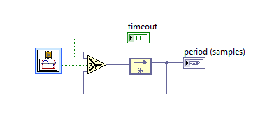
I need measure the frequency of the signal sinuoidal that is developed by using LabVIEW FPGA. I tried to use the block analog measurement period.
The value that I used are: 0 threshold, hysteresis 0.5.
However, no matter what the frequency, the period is always zero.I also tried different threshold and hysteresis values, but it was in vain.
I would be grateful if you could be of any help.
Best regards, Keshav
Hi keshasvew,
This function has a valid output signal that becomes true once per period, so it is likely that you are actually getting a good result, but never see. You will need to add a bit of code to output that uses the valid output signal to lock the result of the last valid measurements. You should also monitor the timeout output, which will remain if you get no results at all generally true.
-
Player Code VITC/CTA time analog PCIe with ESXi
Hello
We have two PCIe analog LTC/VITC time Code Reader (Adrienne card) we would like to install on one of our virtual dedicated server
My question is, how can make us it one of the Virtual hosts to recognized this card and use it or its automatically detects?
Please advice
Thank you
You can't do work at all - random PCI cards may not have sent resources to a virtual computer.
-Matt
Maybe you are looking for
-
Stupid problem... can't access app store
Hi, because of a failure of ssd, I installed on an old hdd 250 GB mountain lion. This facility is very good, and I want to upgrade to the el capitan. I click the app store icon and click on hard find sign in button, where I'm presented with a newspap
-
Android tablet with docking station: table of the emoticons are not more
Skype for Android: since the last updated version, I can't view the emoticons for IM table. I use an Asus Android tablet placed on a docking station (external keyboard). When I click on the smiley face in the message new message, nothing happens. Whe
-
OfficeJet Pro 8500. orientation of the page when printing double-sided it is backwards.
OfficeJet Pro 8500. orientation of the page when printing double-sided it is backwards. How to change so when doc is printed can be read like a book? I don't know where to find and change settings. can you please help? Thanks in advance Anna Anna
-
Personally, I am frustrated to discover file that are currently hidden by vista. For example my temporary Internet folder located in my Temp folder If I open Explorer and browser to the Temp folder is empty - no doubt. It doesn't even have a drop d
-
You will need to turn on computer OnMy (NAP).
How can I turn on my computer network access Protection and how do I do this?