integration of the acceleration in decomposition signal
Hello
I have an experimental acceleration signal deteriorating weather
I want to get the speed by integrating this signal. Practically speed signal should also disintegrate over time. But the built-in signal isn't decomposing? When I make a mistake?
VI corresponding and the AccelerationDATA is in the attached files.
Thank you in anticipation
Looks like you have some positive DC offset in the accel signal which then joined in a speed ramp. A quick and dirty of approximate solution would be to subtract off the coast of the straight line integrated speed adjustment.
-Kevin P
Tags: NI Software
Similar Questions
-
Integration of the signal from Y1 to Y2
Hello guys,.
I have a problem and I would like to ask your help, look, I built a VI that supposed to be able to integrate a certain value Y1 [increase] signal to another value Y2 [who]... Please see the photo.
Right now I am only able to identify the values on the axis of time and points [X] index.
The attached program, it is able to integrate some X 1 X 2 value another value (this is useless to me)
What I really want to do is to perform an integration of the signal using the y-axis, by selecting the first value [Y1] when the curve is raising and the second [Y2] value when the curve is declining
How can I do this? You guys have any ideas?
Please help me
I have attached a diagram of what I want to do, the VI and a TXT file with data that must be integrated
Thank you
SergeArmz
This is because the sliders are locked to the plot. So they can only go to the values where there is a data point. If you create an indicator of table and look at the data values are near index 106 (X 1 Index), you'll see that the intervals ranging from a few thousandths to 3, 4, 5, between the points.
You can create a free slider. It will not focus to data so the location of the cursor can be anywhere in the plot. The increments on which depend on scale of the graph. I get = 0.002 dX and dY = 0,096 on the chart on the version I posted earlier. I connected the slider. Bouquet to the threshold instead of 2 Y1 and it changes the area under the curve in small increments when moved up and down along the steep part of the curve, which is what I expected.
Lynn
-
Integrate the acceleration to get speed using time domain mathematical
I'm trying to do something simple, but have not found the answer to my problem.
I have a loop that couple as input and calculates the acceleration; See attachment.
I'm trying to calculate speed using acceleration.
I used the function of continuous integration of time mathematical field, acceleration plugged as a signal, but the speed that it displays is not correct.
If the acceleration is 1 / s ^ 2, the calculated speed is tens of thousands in / s in the second. This is not true.
What I am doing wrong?
Thank you
Looks like I posted this in the wrong place. Don't know how to delete it well.
-
Integration of the IPM with EBS
Everybody, hell
My IPM server: 11.1.1.3 version (linux)
Server version: EBS R12
I m following the sub process.
Document download (for KFI) through document capture, then it goes to the IPM server.
Then, in Server EBS, click the zoom button, browser task IPM page is open.
Open as user1:
Push data into EBS seeking task IPM viewer data.
Save it in EBS. Click on the approval of the Bill, give an authorization to obtain data to a particular user.
Log in as User2: not found a job.
Error in the BPEL instance is as below:
* < part name = "summary" > *.
* < Summary > Exception occurred when the link was invoked. Exception occurred during invocation of the JCA binding: "binding JCA execute operations reference 'Get_InvoiceTransaction' have to: Interaction processing error." Error during execution of the BPEL_RETRIEVEINVOICE processing. Interaction AXF_VALIDATION_IMPORT_PKG$ RET API. An error occurred during the processing of the interaction to call the BPEL_RETRIEVEINVOICE. AXF_VALIDATION_IMPORT_PKG$ RET API. Cause: java.sql.SQLException: invalid name model: AXF. AXF_VALIDATION_IMPORT_PKG_R_I '.» The called JCA adapter threw an exception of resource. Please review the error message above carefully to determine a resolution. < / Summary > *.
* < / piece > *.
* < part name = 'detail' > *.
* < model name invalid detail >: AXF. AXF_VALIDATION_IMPORT_PKG_R_I < / detail > *.
If someone can tell what packages are used to integrate IPM and EBS.
Here are the names of sql file for the integration of the IPM with EBS:
PATH\CREATE_TEMP_TABLE. SQL;
PATH\AXF_VALIDATION_IMPORT_PKG.SQL; s
PATH\AXF_VALIDATION_IMPORT_PKG_BODY. SQL;
PATH\AXF_PREIMPORT_CUSTOM_PKG. SQL;
PATH\AXF_PREIMPORT_CUSTOM_PKG_BODY. SQL;
PATH\BPEL_11G_IMPORTINVOICE. SQL;
PATH\BPEL_PLACEIPMVALIDATIONHOLDSON. SQL;
PATH\BPEL_PREIMPORTCLEANUP. SQL;
PATH\BPEL_UPDATEHOLDLIST. SQL;
PATH\BPEL_VALIDATEINVOICE. SQL;
PATH\BPEL_RETRIEVEINVOICE. SQL;
PATH\BPEL_GETORGID. SQL;
PATH\EBS_CREATE_HOLD_LOOKUP. SQL;
Please answer me ASAP.
Regarding
JyotiThe problem with the documentation, is that there is no mention of these SQL files that need enforcement. Those that must be performed and visible in the schema of the user of the DB that you configured in your DB Adapater. There are many stored procedures using the model of Accelerator AXF appearing in these SQL. I believe (from memory) is grant it access to one, but I do not see that in your list, and you list looks like also a bit incomplete, which version of the model are you using?
-
Why the extreme to express signal is broken
I have an Airport Extreme b, g, n, ac cable (ethernet) to my router Verizon Wireless. The router has been updated by Verizon end of last year and works very well. From there, I have an iMac with 802.11 b/g/n/ac cable into the extreme as well. I have a Windows pc in another room wired with ethernet to the extreme as well.
At the back of my house, I have an Airport Express b/g/n I used to extend my Airport Extreme signal for the past 18 months without any problem. I had problems of signal with the Express and it seems to re-defining the Express worked, but the image of my signal has changed my Airport utility on my iMac. Previously, the signal was solid from the far down to the Express, and the image on my iPhone 6, at the launch of my Airport utility has been broken from the extreme to the Express.
Now the images are reversed where my iPhone has the solid signal, and my iMac broke the line signal. Someone knows why? It works, but the lines threw me.

A dotted line between the terminal of the AirPort Express and AirPort Extreme indicates that the Express connects to the extreme by using a wireless connection.
What do you want?... or... the Express linking to the extreme by using a wired Ethernet cable connection? If If this is the case, there should be a continuous line between the Express and Extreme.
What device do you have used when you reset and reconfigured the Express... the iMac or the iPhone?
Did you completely turn off the iPhone, has waited a minute or two and then he fed up and checked the AirPort utility again this way?
-
Search engine Google which is integrated in the browser settings
Search engine Google is integrated into the browser. How can I set it so the search results will be shown on a new window, as the fact of the toolbar Google and in the same window (after entry)?
in your topic: configuration settings
- Browser.Search.openintab user set to true
See https://support.mozilla.com/questions/899856
with or without the parameter, you can do something, concluded the
Search bar or in the location bar to open in a new tab with "Alt + Enter". -
AZ1VR Action Cam Mini with a Wi - Fi connection is the GPS integrated into the handpiece
I have the new AZ1VR Action Cam Mini with a Wi - Fi is the GPS integrated into the handpiece
cannellaj wrote:
I have the new AZ1VR Action Cam Mini with a Wi - Fi is the GPS integrated into the handpiece
Yes, get the GPS with the AZ1 to remote LVR2V wrist. You must also update the firmware in both devices. I have both and they work great.
-
Satellite A110-149 - HPET chip integrated into the southbridge?
Hello world
Could not find this information anywhere, so I ask you.
Don't the Satellite A110-149 has HPET or HPET integrated into the southbridge chip?Kind regards
CharlyHello
It is not known to me, but maybe this info might help you:
My knowledge of the computer laptop Satellite A110-149 was equipped with processor Intel CELERONM-430 YONAH (1.7 GHZ) and a RC410MD ATI graphics card (ATI Radeon Xpress 200).Here are all the details I could find on this device.
-
"Protection of the integrity of the system.
I know that Apple has replaced the old system with a new permissions, because I had to disable the other to use my vertical mouse move.
What are the effects downstream of a deactivation of "Protection of the integrity of the system"?
What are the alternatives?
Deactivation of "Protection of the integrity of the system" would explain the bugs some of us have some with dvd players?
It would open up your machine to potential piracy as well as the loss of control over the permissions to change by ill-conceived installers. If security is a concern let alone SIP.
-
How to change the configuration of the BIOS with NO SIGNAL - to accept the new card PCI - ex
Compaq Presario SR2030NX
Product #RJ036AA
S/N {removed privacy}
MB: ASUS A8M2N - LA
Bought: October 2006
OS: Windows XP Media Center 05
New graphics card: MSI N210-D512D2 graphics card GeForce 210-512 MB, DDR2, PCI-Express 2.0 (x 16), 1 x DVI, 1 x VGA, DirectX 10.1, mono-emplacement
New: 480w PSU
ERROR: NO SIGNAL on monitor and can not reset the BIOS to accept the new video card in the PCI slot
PROBLEM: The user reports the monitor suddenly became white with blue lines finally erased. On start-up, the screen shows "No Signal" then turns off.
Troubleshooting has included:
Fixing monitor with its cable to another PC - monitor work
Fixing working monitor and cable to the PC - No Signal
There is no boot beeps, fans, lamps, not work cable defeated, no video. I concluded the embedded video component failed.
Installed the new video PCI - ex card and new power supply 480w and still get NO SIGNAL. New video card specifications called for a minimum 350w power supply. The fan on the new video card PCI - ex works. Search on the HP Support pages indicates that the BIOS should be modified to change the type of PCI slot type in-flight video. Makes perfect sense to me, sounds like it might work.
How to reset the BIOS when you do not see what you are doing?
I have moved the jumpers to reset the CMOS, but cannot tell if it worked or not. I tried a couple blind BIOS resets, but I could do this for months.
If I could determine the Version of the BIOS, I might be able to blindly to reset the BIOS. The Compaq Options of Menu and "BIOS Setup Utility information" web page provides instructions for BIOS version 6 or less and version 7 and greater - menus and access steps are very different.
QUESTIONS: How to determine the version of the BIOS. Which key I hit to access the BIOS (F1, F10, esc, Del)? Which menu I followed to reset the type of video, so how can I save and exit?
Thanks for any help
GJBThank you Paul,.
I didn't know that it was just a function of Regedit - piece of cake.
-
How can I measure the voltage of a signal?
Well!
I'm trying to read the voltage of a signal using acquisition data PCI-6229 card.i am giving the signal as an input to the DAQ card and try to read the voltage level. The range of my signal is 4.8 ~ 5.5 VDC but the results are not accurate, such as measured with DMM. My code is as follows:
1.i m using DAQmx create channel to create an analog input channel
2. then a sample clock with finite samples, sampels by channel and set the rate of iteratively
3. then I start the task
4. analog playback 1 DBL AK1 N sample d
Pressure readings I am differs widely that the actual.e.g a signal measured with DMM is 5v but when applied to the DAQ hardware and measured gives 6v.also I have to define minimum values and maximum in VI... If I put 4 to 5 maximum and minimum to measure a 5vDC signal it gives good result. , but if I change the maximum setting to 6v then it gives me results.also bad behavior is different for different signals for example when I measure a 6.5 VDC to signal that it shows me the voltage as 7.3V...
Photo of my code of VI is attached... Please answer... or give me another code that works fine at the voltage of a signal reading.
-
Integrated above the graphics card dedicated graphics card, I think?
OK, just to put my problems in perspective, I have a laptop-> Hp pavilion dv6 (on the laptop). It is 2 months old, has a processor intel i5 2.30 GHz processor (Duo of course). I have a graphics card integrated on the motherboard according to the usual and a dedicated Radeon 6490 M. in the past, I've never used Nvidia so I'm not at all familiar with the material.
The problem I have is when I go to play a steam game (for example today, counter strike source (CS source)) said that the graphics card I use is not known for their serves. Then I'm fine, if that's the case, the computer must choose using built-in dedicated memory (the best clear). Now for the players no, engine cs source is not really powerful compared to our days the games.
My logic is that a graphics card as up-to-date as mine and the fees I paid for the laptop, I should have dedicated memory and computing power necessary to run the game to its full potential. Its really frustrating, I suggest that person never buy HP again. I already have so many problems. Maybe it's not right to blame the company material, but most of the problems were hardware problems (a part of the single Pass system - TERRIBLE!). I'd appreciate any help, ANY HELP reallly! Thank you
Hello
Your PC think that Steam does not need a lot of graphics computing power. So, it's not getting 6490 m and thus, Steam only detects the integrated graphics card. What you want to do is spend on 6490M before launching Steam.
Read this http://support.hp.com/us-en/document/c02731962#N347
It solves your problem, I hope
-
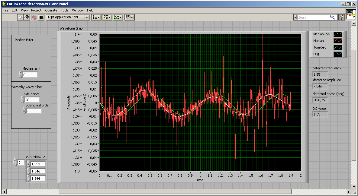
How can I remove the noise of a signal?
Hello world
I need to extract the phase of a signal of 1.5 Hz which has little noise (see attachment files) and MAX I was recording the signal to 500 Hz. I use the filter of Labview tool value 'smoothing' with a factor equal to 3. Could someone tell me if using the right tool for what I want to do? If so, is-3 a correct number of retativaly? Looking at the result of the signal is much better.
Thank you
User
here still to play

I did not use the ordinary filter, but also more you know about the original signal, the better your filter or fitting can be.
If you know it should be a sinus (maybe even with a constant frequency) and you want the phase, go with detection of tone or a linear adjustment...
the median filter is good against the spikes, the filter of SG will make an adjustment of polynomial (original designed for adjustment of Spectra but it's also nice noise with propper settings)
Uups, the pic was taken without median filter...
If you tell us more about the signal, we could offer best filter. And keep in mind that most of the filters have an influence on the phase of the signal (late phase/group).
-
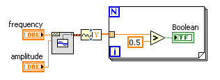
With the help of modulated signal pulse width (square wave) to control when a signal is enabled or disable
Hello all
I am using a modulated signal to labview created pulse width (square wave) to control when a signal is activated or not.
Here is my logic and a concrete example:
(1) the wave source signal is continuous
(2) use a PWM (square wave) created in labview to control when the signal is enabled or disabled
(3) if the PWM (amplitude) signal is superior to 0 play signal PWM is not greater than 0 do not play signal.I use actually this to the sequence step / pulse several distinct magnetic coils using my audio card (which has several channels of audio output), I have a signal in labview played constantly. As to compare it to the PWM (square wave) which controls whether or not the signal is played on each separate channel. That way I can control which coil is on and offshore and in what order they are activated.
I couldn't find an edge detection for a square wave created in labview, so I tried the limits, but it doesn't seem to work unless I change the phase manually and it only goes 1-1. I'm just trying to compare the PWM (edges of the square wave) already created by labview / play a signal if the pulse is greater than 0 and it shuts off the signal, if she is less than 0.
Should I do this another way
TIA
A waveform contains an array of values. You must check every value and respond accordingly:
-
Filling of the specific category of Signal on the range of functions
Hello
Does anyone can help with advice on how to complete the specific category of signal on the palette of functions of block diagram?
Thank you
Hi Ewan,
Uninstallation and reinstallation in order would ensure that everything was properly associated. However, I don't think that this should be necessary in your situation. Please go to control panel > programs and features > National Instruments software to see the full list of National Instruments software you have installed. From there, you should be able to select any individual installation from the list and select "repair". Instead of just seeing that something is already installed and the output, it should go through the installation and check alteration. In addition, this should add the correct associations if they were currently missed due to the order of installation.
Please try to run a repair of 2013 SignalExpress and restarted your computer, then check if the LabVIEW function palette is completely filled.
Thank you!

Maybe you are looking for
-
How to do a full (level 4) uninstalling the software of a photosmart c6180 all-in-one printer?
I have to do a complete uninstall of my printer, because when I try to uninstall from the Control Panel, or the cd, it does not completely uninstall! Then, when I try to re - install, no icons are visible! and I am unable to view or change the print
-
Some web pages are not available with Satellite Pro 4600
Installed a new hard drive and Windows 2000 in my laptop and now a weird problem. Both Ie6 and Firefox accesses some Google Web sites (I can get on and get results), some sites UK & US, etc., but toshiba support page I can't seem to ebay, bbc, most o
-
WVC210 display of the camera does not
Hello I have a wvc210, the small LCD screen on the camera does not do anything, so I can't determine what IP it works stop. The lights work and it starts ok. Any suggestions?
-
Fonts installed - available through programs - do not appear in C:\Windows\Fonts? Why?
Slowly, I'm losing my mind here! I have a few fonts installed; specifically, variants of Helvetica Neue and Janson Text Std LT. If I use something, say, Photoshop, all my installed fonts and all their variants appear and operate as it should, so I'm
-
BlackBerry smartphones 'Advanced settings' missing! (Verizon Wireless)
The "Advanced settings" option in BIS is missing... I don't know if there is a problem with just Verizon or what? It is absent from the version of regular desktop browser and mobile version. Verizon didn't know what was happening and referred me to B