Internationalization of the connector generic technology
I created a connector generic technology in IOM with 'Cp1251' as the encoding of the file. But Cp1251 supports only English characters. I want to load the data that have some French characters.A recon event is received when we try to load the French characters, but the data received are distorted. And since there is no matches found for the Organization of the data for example, recon fails.
If any of you have worked on the internationalization of the generic connector, please let me know the solution.
You must use an encoding of UTF - 8 type and also make sure that the file is in UTF-8 format :)
Thank you
Suren
Tags: Fusion Middleware
Similar Questions
-
Fluid was detected in the connector of the lightning.
I get a warning when my iPhone is plugged into its lighting cable saying 'Disconnect accessory lightning' "Liquid has been detected in the connector of the lightning" ' to protect your iPhone, unplug this accessory of lightning, and allow the connector to dry. "
The cable is as dry as a BONE, the phone has never been exposed to water, other than standard moisture. I have several cables, and it happens with all of them.
Clues?
Thank you.
Try a forced reboot. Hold down the Home and Sleep/Wake buttons at the same time for about 15 seconds, until the Apple logo appears. You won't lose anything.
If the steps above do not help, you may need to test in an Apple store.
-
I need the list of pins for various connectors case-Strip pin, especially J24 but other multispindle those too.
Manual of Tyan S2915 Board for is a different version than that of poor quality that they OEM would be at HP for the 9400 and HP Tech Ref for the 9400 only provides pinouts for connectors well defined including pinout lie anywhere.
The connector of the Panel before xw9400 J34 (there is no J24) pinout, the mother, is map:
There are 2 key positions (lack of spindle) on pins 10 and 15. Use these empty pins to help identify the signals.
The pinout is very similar to other former workstations HP. A few tips:
-Pins 1 and 3 are for the harddrive activity led.
-Terminals 2 and 4 are for the power light. HP systems have back to back LED connected between these pins. A green is on and functioning normal and red lights (and flashes error codes) when there are errors.
-Connect a momentary between pins 5 and 6 switch will turn on the computer and off.
-Connection of a momemtary between pins 7 and 8 switch will force a system reset.
-PIN 9 is designated as + 5V, but it is powered by a 100 ohm pullup resistor to + 5V, so it will not provide a lot of power. FOR INFO.
-SPKR + and SPKR - are for the internal speaker.
Most of the other connectors xw9400 follow standards of industry, i.e. the IDE drive and floppy connectors.
Is there anything else you want to know?
-
Satellite L750-1PH - how to activate the Turbo Boost technology?
Hello
I want to activate the * Turbo Boost technology *. But I don't know how.
And the fan makes a lot of noise and hot air of spit.I will be very happy if you could help me :(((
Thank you
Best regards
* Bahad? r ACARYou have Intel Core i7-2670QM processor and this processor supports Intel® Turbo Boost technology 2.0
These features of the CPU can be enabled and disabled in the BIOS. But just in case where this option is available in the BIOS.
When this option isn't available, you will not be able to put ON or OFF -
How to disable the functionality of the hyper-threading technology
How to disable the functionality of the hyper-threading technology
Hello
I put t know what BIOS you have, but generally you can activate or deactivate this option in the BIOS.
-
PIN of the connector broken but the charger works always, safe to use?
On food, to the end that connects to the computer, the connector is cylindrical with a thin metal rod in the middle. This rod is broken, but taken light goes even when the connector is connected. I can still continue to use the charger or the computer may be damaged? If this isn't the case, I'd appreciate an explanation because I am familiar with electronics. What is the function of the centering pin? The other end has a third PIN to ground. Thanks in advance
-
That means the following message from VI Analyzer: "part of connector of this VI is not a part of the connector that is specified by the user."?
The VI it references has 4 connections: 2 in. and 2 outputs. He was selected from a template.
Everywhere where the VI that it references is used is relinked and properly connected.
While it has been warned?
As it says, this is just a warning.
Many programmers standardize on a small selection of models of connector. VI Analyzer will tell you if a different connector pane is used. One of your screws apparently uses a connector part 2 x 2, which is not used very often. (Example (1) it must be changed if you need connectors later, (2) it does not match the gap-type-in and error-out lower terminals, (3) if it is mounted in series with subVIs most popular models, the son will have elbows and things not the line-up, etc..)
Two choices:
- If you are really in love with the part of connector 2 x 2, add it to the configuration of the parser as a reason accepted.
- Stick to a more standardized connector component, even if not all the connectors are currently used.
-
I have a PCI 6519 data acquisition card. I want to install it on the PC and use it outputs to control a robot. I have problems with the connections to the terminal block which is attached to the cable.
What type of connections I do for the acquisition of data PCI 619 card pins? What I have to give it to the ground and the CCV on the pins of the connector myself? What should be the value of the SCR I need to give to the PIN?
-
Z400: Z400 firewire pinout of the connector?
I noticed that the connector on the front panel 1394 connector 12 pin rather than the standard 10 pin. Does anyone know the pinout? It is not in the maintenance manual. Thank you!
Here is the pinout of the Z400 J13 1394 header. Keep in mind that it is looking at the head of the motherboard, and not the connector at the end of the connector to the front panel, which could be a reflection, depending on how you look at the connector.
The best way to determine the pinout is to use the keyed/missing pins as a refrence.
-
Why the connector pane displays a different connector for lvclass?
Picture is worth 2000 words...
What is the special problem with the connectors on the left & right superiors?
I have other lvclasses, but they do not have the points X shaped...

Those who are marked as dynamic connections distribution (take a look on where you would be required). An entry from JJ means that it is a VI that is designed to be substituted dynamically at run time according to the type of class actually present on the wire.
-
under condition of read/write terminals on the side of the connector (basic training 3)
Hello
During my practice towards the review of the CLD, I examine the Core 3 online training material too. I just read a few tips of 'best practices' on the forum, for example this post:
It should be noted, that we should not use terminals (which are on the connector pane) to the inside of while loop or condition of the structure. Neither control, nor indicators (read/write terminals): "terminals conditionally read or written on the side of the connector are BAD!"
I can find many examples in the online training materials, when the indicators and controls are placed inside while loop and the case of structures in a Subvi.
I guess I should not do this during my review of the CLD, as they will run benchmark on my project? Should not be the core training materials updated some time? Or it's just not too important to have terminals on the outside? I would lose points during the CLD Exam my project as in the Core 3 screws?
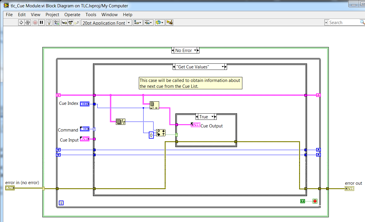
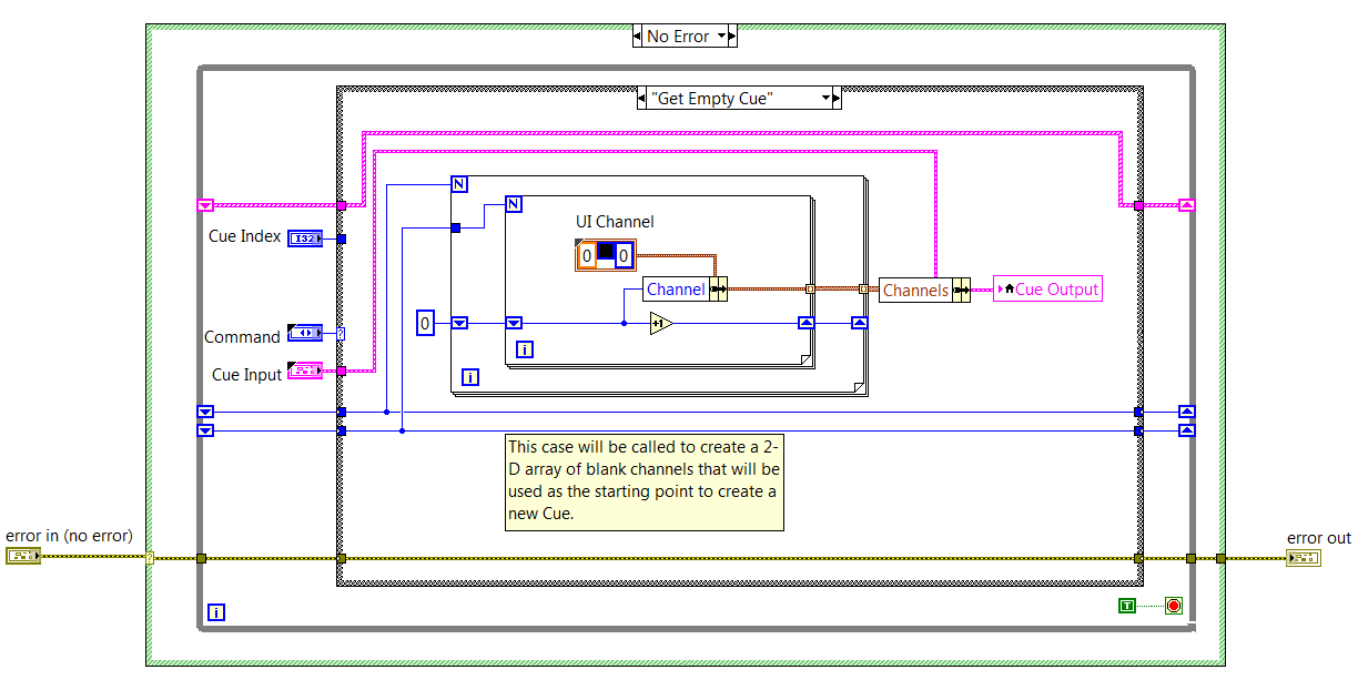
example 1: Core 3, exercise 4-6 design of an error-handling strategy:
EDIT:
What's even more ugly in this project, is that, in the case of 'Get empty Cue', the Cue output indicator is updated via a local variable, because the indicator is not accessible via 'outside ': wire
Nice catch on the training material. that the application would take an if subject to a review of the CLD test graders.
As noted in the nugget: sentencing of perfomance for conditionally reached terminals is a function of the size of the data. So, it is sometimes acceptable for simple data. The larger point being to learn about compromise and make the right choice for your code.
Preping for the CLD on other means of hand knowing that VI Analyzer will run on your project. Like any other code review you walk in - know the guidelines for the review and code to ' review ' as well as 'reply spec.'
I've not seen an instance where an example of shipping (2013 and later versions) would fail this test VIA (there are a few screws deep inside the vi.lib which can date back to before the adoption of this recommendation from style)
-
What is the connector 100 OEM part number used on the PCI-DIO-96 map pins?
I have a PCI-DIO-96 card and I want to make my own custom cable to connect to the connector of the OID 100 i/o pins. However, I can't find any reference to the reference OEM of the connector used on the PCI-DIO-96 Board so I can order his companion.
If anyone knows of any information about the connector part number 100 pins used on the PCI-DIO-96 Board, I would be very happy to know this information.
Thank you.
Well, I found earlier the information I was looking for... Page 1-3 of the PCI-DIO-96 manual (section "Custom wiring"). FYI, I have the March 2009 edition of the manual. (it helps to actually read the manual, huh?)
In this section, two OEM mating connectors are suggested:
Company AMP (P/N 749879-9)
Honda Corporation (Ref. PCS-XE100LFD-HS)
I went to the website of the GPA. There are actually two AMP parts active that do the trick... the P/N given in the PCI-DIO-96 manual map is the non-RoHS connector version. The compliant version RoHS/ELV of this connector is AMP P / N 5-749879-9. (Note than the previous one "5" in the part number)
For the purposes of referral, the connector is a series of 0.050 "SCSI cable insulation Dispalcement Connector [CID] (100 pins to 0.050" Ribbon).
In the United States, Heilind Electronics (http://estore.heilind.com) carries the AMP part. Minimum purchase is six parts. At the time of this announcement, they have a few hundred in stock.
If all goes well, that helps other readers.
-Mike
-
Get the reference to control of the connector pane
I'm trying to get a reference to a control associated with a specific index in the connector pane. I see that there is a method to assign control to a terminal, but not get control of a terminal-specific. I know that I can enumerate all the controls in the connector pane, but it doesn't specifically tell me where they are.
Edit: I see, there are private methods to get and set properties that can have this info, but because they are undocumented, and they are properties of a VI that is binary, I can't bone.
When you read the Controls property of [class ConnectorPane], he puts back them to you in the order of terminal. There is a VI in the examples folder that shows you the order for each connector component model (visually). I don't have LabVIEW in front of me at the moment, but it should be examples\Application part Scripting\Connector Control\VI, or something like that.
-
Subvi value not updated when it is connected to the connector pane
I have a legacy program that computes a frequency when a value changes of sensor (falling edge essentially), and I'm trying to convert the logic to a Subvi, so I can use it for 44 other sensors. The program first used a large number of property value node, I discovered is not good for subVis. I converted them to local variables, but I still have questions.
As soon as I connect something to the output pane that closes the update value question. If I remove the connection in the connector pane, it works fine.
a picture of the block diagram is attached. I tried to connect Freq and frequency of output to the connector pane, as soon as I connect it to the component connector to work properly to date do not at all.
The VI is configured as non-reentrant.
Thank you
-
Could not load the connector pane
Has anyone else had this error before? I asked tech support, but they had not seen anything like that either.
System:
Windows 7 Professional (64-bit), LV2010 (10.0f4 v, 32 bit)
The repro steps:
(1) create a new VI (any method)
(2) right-click on the icon and select 'display the connector '.
Expected result:
Connector pane appears
Actual results:
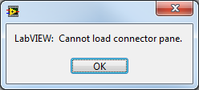
Error message - "LabVIEW: cannot load the component connector.
Workaround solution:
Click OK in the error message. The connector pane then charge and everything works fine.
This happens only the first time that I open the component connector on a VI; It does not happen after that I have opened (even after the backup, etc.). Technical support had me try the f4 patch, reinstall/repair of LV2010, and I even made a compilation of mass for good measure. It is not a real problem (I just click OK on the error and go about my business), but I'm curious to see if anyone has seen this kind of behaviour before.
-Daniel
So if you have an archaic line in your file LabView.ini (maybe since way back in the days 6/7/8.x and it is simply copied to after each upgrade, then copied on new computers) and it looks like this:
defaultConPane = 4185

Then you could try to load a connector component that does not exist. It should perhaps have been 4815, or something else. In any case, delete said line and everything is fine.
http://digital.NI.com/public.nsf/allkb/279F064F0688C114862570900057678C


Maybe you are looking for
-
Hi I want to find the place to the creation of my iCloud account
Apple customer HI my question is too imforted please answer me I'll be happy two years ago, I created this account ***@icloud.com I forgot creation of place please help me and tell where I was created < email published by host >
-
Keyboard satellite 2430 problem when press z,?, Fn or the arrow keys
When one of these keys are pressed (z,?, Fn or the arrow keys), the cursor control mode light will light up and the keyboard no longer works. In addition, the context menu of the application randomly appears and disappears, and when I'm using a text
-
Captian El is not installed on the SSD disk fusion part after recovering from the internet
I found that my Mac OS X El Captian is installed on the part of the hard disk of 1 TB disk fusion rather than the part of the SSD drive after the installation of recovery of the internet. And the SSD disk fusion part seems to be "not fitted"... May I
-
Today, only with Firefox open, I get a strong Mermaid CONSTANT (like Super Mario). I uninstalled then reinstalled... siren always there. I didn't Remove Favorites, what should I do? Is it possible to save my favorites until I kill them? Will be more
-
Hi all. I read everywhere and personally see no reason that neither of them should work, but I've read some reports of people having problems with the Corsair does not and having to go back to her and the second pair does not. Then the HyperX for som