Isolated ground and analog ground in Multisim
What is the availability of isolated or analog grounds in Multisim? Multisim allows 2 main types of designs, standard ground (can also be called grounding, represented always net '0') and digital terrestrial, but sometimes in a design, you will need several references to the ground for the different areas of design, including a ground Earth or chassis point, digital and analog ground terrestrial and sometimes ground isolated.
How that this can be accommodated in a modeling Multisim and the point of view of layout?
Kind regards
Patrick Noonan
Business Development Manager
National Instruments - Electronics Workbench Group
50 market St 1-
South Portland, ME 04106
Phone: 207 892-9130
E-mail: [email protected]
Here are examples:
Other reasons Example.ms10 - example of Multisim illustrating how to connect and measure, CGDN, IGND and V_ISO and ALWAYS
Isolated from Source and Earth Example.ms10 - another example showing IGND and V_ISO measured relative to the Earth (0 net)
Special_Gnds.Prz - update database file - creates the new family of "Special_GNDs" (Multisim 10.1)
Thanks to the original user who have requested them.
Kind regards
Patrick Noonan
Business Development Manager
National Instruments - Electronics Workbench Group
50 market St 1-
South Portland, ME 04106
Phone: 207 892-9130
E-mail: [email protected]
Tags: NI Software
Similar Questions
-
Terca M4: How to activate the external ports, DVI and analog?
Please can someone please tell how to activate the two external ports. I would use two DVI and analog to the office. Currently if you activate a second screen machine sets up the flat screen and the other the DVI external display. Is this in any way about this?
See you soon
Hi Matthew
As far as I know you can connect an external monitor or a TFT. For this you can use the VGA (15-pin) port or DVI - D video, supported by PortReplicator III (PA3314E).
Sorry, but I don't understand why you need the two holes at the same time. How many external screens that you want to use? Sorry if I'm missing something but perhaps you can explain your wishes more precisely.
Good bye
-
Digital and analog inputs simultaneously - NI USB-6009 and NI USB-6212 - ANSI C
Hello
I'm reading at all times and at the same time analog and digital inputs. Digital and analog samples must be sampled at the same clock and acquisition should be started (triggered?) at the same time (I don't want, after some time, analog reception more digital samples - the opposite is also true).
I found an example (in C source code) "National Instruments\NI-DAQ\Examples\DAQmx ANSI C\Synchronization\Multi-Function\ContAI-Read dig Chan" and tried to run with two USB cards: NI USB-6009 and NI USB-6212. Unfortunately, the two results by mistake, as described below:
DAQmx error: the requested value is not supported for this property value.
Property: DAQmx_SampTimingType
You asked: DAQmx_Val_SampClk
You can select: DAQmx_Val_OnDemandTask name: _unnamedTask<1>
State code:-200077
End of the program, press the Enter key to exit-Is it possible sync analog and digital acquisition in the paintings?
-If so, how?
Thank you
Hello tcbusatta,
Two of these modules, USB = 6008 and USB-6212, support only timed software inputs and digital outputs. This means that you cannot define material timing (like finished sampling or continuous) for these modules. Digital lines can be retrieved or written once to each call DAQmx read.
This means that you will not be able to get any type of synchronization tight between the analogue and digital channels. You will need a Board such as the NI USB-6341 in order to synchronize the AI and DI closely.
-
6009 outputs digital and analog input synchronization
Hello
I work in a program NI 6009. I want to leds by car with outputs digital NI 6009. For example, leads first will be on until what 200 micro seconds then second led will be on up to 200 micro seconds, and then first of all led will be on up to 200 micro seconds. I'll take led with photodedector signals and connect analog output photodedector input NI 6009. I want to synchronize the outputs digital and analog input and separate the first and second led signals the analog input for NI 6009 channel. How can you do with NI 6009? Please ADV
You can not do with the USB-6009 case. Its outputs digital are software with a maximum speed of slightly more than 100 samples per second. The outputs can produce 200 microsecond pulses and cannot be synchronized with the analog input.
You need a device with outputs digital hardware timed or counters that can produce a pulse outputs.
You can synchronize a bit digital output and analog input recording signal on an additional channel to HAVE. Will allow you to see the photodetector and LED the drive with the same schedule and such resolution as described by the sampling rate I. The maximum sampling frequency of AI on the USB-6009 case is 48 kHz that is shared by all channels. If you have two lights to led and photodetector two signals maximum sampling rate would be 48 kHz/4 = 6 kHz which is barely fast enough for your 200 US signals. For more than 4 channels, it won't be fast enough.
I suggest a simple oscillator circuit building and use it to clock a flip flop. This will give you alternating signals to drive the LEDs. You can use a line to reset the flip flop to give you control without the need for high speed.
Lynn
-
Questions about the synchronization between output and analog input
Hi all
I now have a simple task which head a signal voltage (from PXI ao0) on a circuit and then your comments a voltage at the terminals of a component, for example, that one of the resistors in the circuit, through ai0 on PXI. So in this case, the synchronization between analog input and analog output must be made to avoid error of phase shift.
I tried to build my VI by learning this example: https://decibel.ni.com/content/docs/DOC-3882
However I have a few questions.
1. I noticed that there is a merged error fed the "start task" sub VI for the analog output. What is the point of fusion to mistake?
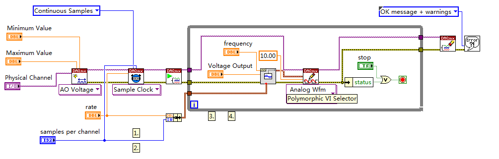
2. I enclose my VI (also shown below) for the output voltage. I put my writing of DAQmx Subvi in the while loop so that I can change the voltage while the VI is running.
However, in the example, the author has been reading outside of the loop and before even the start task. What difference will it make?
3. I have also attached my synchronized VI. I always put the wavegeneration and the DAQmxwrite in the loop. A bulging guard error saying about samples is not available and needs to a higher sampling rate or a longer wait time. What causes this?
I appreciate that these problems can be solved. Thanks to you all.
(1) first you need start the task of acquiring, he'll wait for trigger here. And then you start the build task that provides this trigger. If acquisition could trigger and never start.
(3) you must first write something in the buffer (writing DAQmx), then only you can generate it (Daqmx Start).
Check Cont Gen tension Wfm - Int Clk - no Regeneration.vi in the help-> examples for example.
-
(Vista) Is there a PRACTICE way to switch between speakers and analog headset?
(Vista) Is there a PRACTICE way to switch between speakers and analog headset? Must I ALWAYS return the default setting, depending on which audio output device I want to use?
We have recently installed Music Maker 16. Before that, we never had a need for headphones and a microphone. Now, in trying to use the headphone and microphone - and THEN switch back to speakers - we discover a problem. Apparently, the only way to do it is to change the audio output device by default EVERY time.
The dispute with this cannot be more of this. My son records a beat and singing (with headphone and microphone), and then, play through speakers (so we can all hear), we need to change the default settings. And back... There must be a better way!
Any help would be greatly appreciated. Please talk layman jargon; I'm not a COMPUTER guru. Thank you!!!
Hi AnnieElle,
You will need to switch between the speakers and the analog device and special value to use as the default device. There is no way to set the device to be used at the same time. You can follow the steps below to switch between the speaker and analog device.
1. right click on the speaker icon in the taskbar.
2. click on the playback device.
3. Select speakers or analog device.
4. right-click on it and click on set as default device.
Hope the above information helps.
Thank you and best regards,
Srinivas R
Microsoft technical support.
Visit our Microsoft answers feedback Forum and let us know what you think.
-
Difference between the isolated property and cascade delete
Hello
I property remove relationship in the master / detail in material form. By using the isolated and cascading deletion property, both produce the same result. Setting the deletion as the child isolated property are also supprimés, which is contrary to the statement of isolated property to delete.
Try to clarify my doubts.
Thanks in advanceI rtied using Forms 10.1.2.0.2 against 10 g-data base.
When the isolated use and removing the master, the details are removed from the form, but when commit that the master is removed, the child records still exist in the database.
I guess that there is somewhere is code in your which removes the details.
If you don't find anything, maybe its useful build a testcase very simple to check if it is somewhat related to your tablestructure. -
I have NBN FTTP with iiNet and looking to move to an Airport Extreme. My question is, is there a way I can connect an analog phone to EI or should I get a new phone. I need a by 2-3 cordless handsets so I weigh the cost between a converter or a new device. My phone service is via the VOIP application.
iiNet should give you a wireless modem router... Method NB16VW which includes voip, unless you specifically asked to do not to get.
The method can still be used ATA plugged in the extreme is my guess.
Otherwise, you should buy a VOIP phone... ultimately, it's a far superior solution... The gigaset C530IP round $180 and you can buy additional handsets with her. Quite expensive but big cut above the average.
There are a few old gigaset nine eBay for $75 if you want a good option. Research of F470.
-
Portege M400: Port Replicator support DVI and analog monitor
Hello
I use my Toshiba M400 in the duplicator.
The duplicator has two outputs to a DVI and an external analog output display.I would use both screens at the same time under Windows Vista RC1.
The port replicator manual mentions that this should be possible depending on the connected computer."According to the computer connected to the port replicator, you can connect external monitors to DVI port and the port external monitor and display on both screens at the same time."
Someone he knows the M400 which supports? I only get the external DVI monitor or at work.
(He used to work with my old others and this function was just great).A big thank you in advance.
Rogier
Hello
I'm not sure but pretty sure you cannot connect two external displays at the same time due to the restriction of graphics card for laptop to 100%. You can stretch relative to your office for two screens (one internal and external) or have the same image on laptop LCD and external TFT connected DVI or RGB port.
If I read the sentence you have posted I realized you can use two ports (according to specifications) and use two screens on the same time screens (laptop screen and an external).
All available modes to switch the display to the external one, you can check with the combination of keys FN + F5 or in change of display tab tool mobile extension of Toshiba Service.
-
Digital and analog gain in Script mode
Hello.
5422 module can change the voltage Vp-p order of 05:54 V.
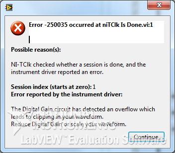
But when I use the property node - digital Gain, after setting the 1.1 V and return to its previous value (V 1.0) occurs the following error:
And when generating a signal of amplitude of 1.1 V signal very distorted.
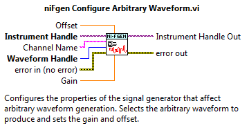
In niFgen configure Arbitrary Waveform VI it is a Gain parameter to control the standard signal (which I understand). Is there something similar for the Script mode?
How to access the analog Gain?
And in general, how to properly use the analog and digital gain in Script mode?
I apologize for possible errors, but the example is not yet complete.
Max O.
Developer of software and engineering,
TeSLa.
Hi max_i,.
Since the ownership of digital Gain help file:
"Specifies a factor by which the digital signal generator multiply data generated before the conversion of an analog signal in the CAD." Saving digital greater than 1.0, the product digital time gain the data generated must be in the range ±1, 0 (assuming that the floating point data). If the product exceeds these limits, the signal generator cuts out the output signal, resulting in an error. »
Digital gain requires the data, being always standard-1 to 1V. The output of 'Ladder' to 'normalise Waveform.vi' here is generally superior to 1, which causes this error 250035. If you search for the property similar to the entry of 'Gain' on the ' configure Arbitrary Waveform.vi ', I advise to use the 'Gain' on the tab 'Arbitrary signals' property in the property node.
Looking at your code, it seems that you try to build pretty standard signals (sine signals). Is that this will change in the future to more complex waveforms? If not, I wouldn't recommend watching one of the examples in the example LabVIEW finder, I find "Sequence of Arb basic Fgen" quite useful. If you want to make scripts as well, I would recommend the example "Fgen Arb Script".
Thank you
David B
National Instruments
Technical sales engineer
-
Digital and analog simultaneous inter channel delay
I need to a simultaneous analog input 1 channel and 1 entered digital who intend to make possible acquisition of maximum speed. Of course I expect no delay channel inter if the two entries on the edge of clock sample even sampling. But this example shows unexpected behavior. Restart acquisition regularly shows different delays inter channel. I hope there is someone there to help out me. See the included example.
I asked the support of National Instruments and they came with an adequate solution.
Time t (0) stamp in the waveform is NOT the start time of the acquisition but it is the time the buffer is read.
To demonstrate this applies the same "pulse train" to the two channels and t (0) all forms of wave at the same time of departure. Observe that the edges of both signals match exactly. Because a single channel is a digital input, we make the logic of levels of tension into account.
Thanks to Henk Talsma
National Instruments
Engineering applications -
Digital and analog generation and acquisition using USB-6251
Hi all
I have to actually synchronize a 6251, USB and USB 6366 Board. I have a vi, which is good that now I am able to use the 6366 as the master and as slave 6251, attached tie. The master generates a digital trigger for (generation synchronization) pulse and the acquisition of the signals on both cards, analog signal ramp and acquires signals. The slave acquires only a series of signals after outbreak.
I want to have the 6251 as master and as slave 6366. The vi attached the other way around as I mentioned above. When I try to use the 6251 as the master, I get an error asking me to specify the clock source (I did the material and some changes in the program as well, as export properly 6251 at 6366 clock).
Thank you
SANJU
Thanks for your reply jonathon,
But in your code below, I coudnt get the Outpput internal PCI-6251/ctrl0...
but I hardwaired the o/p (PFI 12) meter... .and generated a signal meter on this port, I used that as the clock...
Thank you
SANJU
-
9174 triggered output pulses and analog input synchronization
Hello
I have a cDAQ 9174 with a 9215 analog and a 9401 module. I wonder if this configuration is suitable for my use: a trigger digital extern is sent to the system to trigger a task of analog input, trigger a generation of pulses, with another counter, count of trigger events. Using two counters on 9401, it seems I have no left Terminal at the entrance of my trigger signal. The trigger DAQmx vi does not show counters entries in the list of signals; and if I select a PFI line, an error that says that the line is already in use..., I missed a few obvious solution? I have change my 9401 to a 9402 did?
Thanks for any help,
Vincent
Hi Vincent,.
So, looks like you need a single line to use as input to trigger events and another line to use for a generation of pulse output. This should indeed be possible, since the 9401 has 8 lines that are configurable nibble (i.e. lines 0:3 could be configured as inputs, while the 4:7 lines could be taken out, or vice versa).
However, a big caveat with the 9401 is that the lines must be reserved before each task is started. This is a limitation of the direction of the line is implemented in hardware and is common as customers when something they using the 9401. Explicitly reserving your tasks before starting must correct the behavior if that is indeed what you see.
Best regards
-
Switch between outputs, digital and analog input
Forgive me, I'm sure that there is a simple answer to my problem, but being relatively new to LabView, I do not know how to proceed.
With the help of producer/consumer achitecture I am trying to accomplish the following:
Producer
- Relay nearby
- Read the voltage
Consumer
- Compare the voltage to the expected value and append the true/false value in a table.
It will be run 8 times then wait for input from the user through the dialog box run then 8 times.
My question/problem is how I set up so that the digital analog in and out are timed correctly and get a sample of AI after each relay is closed?
Material used is the cDAQ, (2) NI9481 & NI9221 (1)
Attached, is the vi that I came with this day and a diagram to illustrate the intended application.
Any help is greatly appreciated.
-
Using of FPGA VHDL IP and analog output
I use a system with Labview 2014 PXI. I've got Labview FPGA to program and run the card PXI-7854R.
I have the VHDL Code I want to use to control an analog output of the card. I use the IP integration node for this now but I also tried it making the process CLIP and still have not been successful. The problem that arises is that the IP integration node must be in a timed loop, while the analog output indicates that it cannot be put in a timed loop. Is there a way to provide an output of VHDL analog outputs of the card?
I tried to embed a loop timed within a while loop, but it still does not work.
I can't download the VI due to the policy of the company, but suppose I'm generating a sine wave in my VHDL code which must lead to the analog output of the card (the actual wave is company owner information but it is generated by a glance to the top of the table as a sine wave VHDL would be).
In an attempt to work the problem I retried import CLIP of the HDL code in a new project in Labview and VI. I'm still not sure about why it did not work with each other when I tried it.
For anyone who seeks to solve this problem:
I basically used this tutorial for the process CLIP: http://www.ni.com/tutorial/7444/en/
It also explains the differences between the CLAMP and the IP integration node.
Maybe you are looking for
-
Unable to scroll upwards or downwards with the iPhone iOS 10 6 s more
With any screen with my iso 10, it is difficult to move or scroll. Is there an adjustment for this? It's the same thing with the home screens, it is difficult to move to the next set of icons or just scroll up and down with safari. Thank you Bill
-
I'm going to buy toshiba Satellite A50-101 butI ask how hours life and I want pictures for her.Thank you
-
HP advisor and update software
Download hp update and HP Advisor I like to find the link on the site of hp and not from the google search, but I would have it on my laptop and desktop to get the hp and the hp update Counsellor installed on my computer for some reason, he wasn't on
-
Re: P750-13N wrong display driver
Hello I just bought a Toshiba Satellite P750-13N. When I got the laptop, I put my recovery disk disk and down them. I have my setup of the laptop and the loan, but I noticed that I have view the drivers installed. The Nvidia driver and Intel HD famil
-
Personal Hot Spot off, always appears as a choice WiFi
My Personal Hotspot iPhone is disabled, but it always appears as a choice of Wifi on other devices that are nearby. I don't want this index upward as a possible choice, especially in public places, and I have a concern that it drains my battery. How