Isolation between channels SMU 5451
Hello
We try to use the exit CH0 + as a floating voltage source. Our instrument is the NOR-SMU-5451.
It seems that the SMA cable screen is difficult driven ashore by the analog output.
I can't find in the documentation it is possible to isolate the CHx outputs of Earth.
Does anyone know if this is possible or not?
Thanks in advance!
Hello
I looked in your query about isolation and it is not something that is possible with the nature of the card being the only complete reference.
Thanks for posting!
Kind regards
Will be
National Instruments
Engineering applications
Tags: NI Hardware
Similar Questions
-
Generating signals simultaneously on two channels (SMU-5451)
Hello!
I'm trying to generate 2 different signals on the two output port of my SMU-5451.
Signals transmitted from data read from the file of PDM.
I'm able to generate 1 1 channel signal. But I can't ' figure out how to complete the data for my 2 channels memory and let generator simultaneously press these data or their respective!
Can any help? Maybe an example?
Thank you!
Hello Mr. Gambini,.
You can find all the information to do this here:
http://zone.NI.com/reference/en-XX/help/370524P-01/siggenhelp/5451_ni_5450_multichannel_allocation/
Particularly:
"To write waveform data to two channels at once, you must first striping of the data. "Once the data are interleaved, call the VI niFgen write Waveform (poly) or one of the wave functions write niFgen with the channel parameter set to"0.1"
Kind regards
-
Error-1074135024 with the sequence mode arbitrary two-channel on SMU-5451
Hello
I am trying to use both channels on my SMU-5451 and operate in arbitrary sequence mode.
In the build step start, I get the error-1074135024:
Possible reasons:
Invalid value for the parameter or property.Attribute values are not similar in the channels or the specified features. Use a unique channel name or feature name to query the value.
Unfortunately, I have no idea what parameter or property value causes the error.
Initially, I tried this with my own VI, and I was able to run each channel individually, but could not get them both to operate simultaneously. As an attempt to troubleshooting Finally, I decided to change the example of arbitrary signals Fgen (Dual Channel) (which worked properly), to see if I could get it to work with arbitrary sequences. I still get the same error. I enclose modified VI, because it is quite a bit simpler than what I'm running.
I'm under Labview 2012.0.1f3 (32-bit) on a Windows 7 Enterprise (64-bit) operating system.
Thanks for any help you can offer on how to solve this problem!
Bill
So with the help of your VI I have figured out how to make it work.
First of all, your VI I noticed that I should wire the specific channel, I just want to niFgen Create VI waveform, but not in VI of arbitrary sequence niFgen set up. For this I devrais either do not fill in the entrance of the channel, either entry "0.1". This gets rid of the original error message that prompted this post.
Your VI works, but it seems to be designed to write on only one channel at a time. However, I noticed that if I run it with all the waveforms channel 0, change the waveforms to be on channel 1 and click load & sequence, waveforms will be correctly output channels 0 and 1.
Finally, I worked on that the trick is to create an arbitrary sequence, so use the arbitrary Create Sequence niFgen and niFgen configuration arbitrary sequence screw, single-channel waveforms. Then run the niFgen Clear VI arbitrary memory, then create another arbitrary sequence for the other channel. After that, run the generation VI niFgen undertake. And everything works fine! I don't know why it is important to have clear memory arbitrary VI in the Middle, but it seems to be essential for this to work properly.
I downloaded my VI relatively simple test that works properly with this arrangement.
Thank you very much for your help.
-
Peer to peer between SMU-5451 and SMU-7966R
Hello
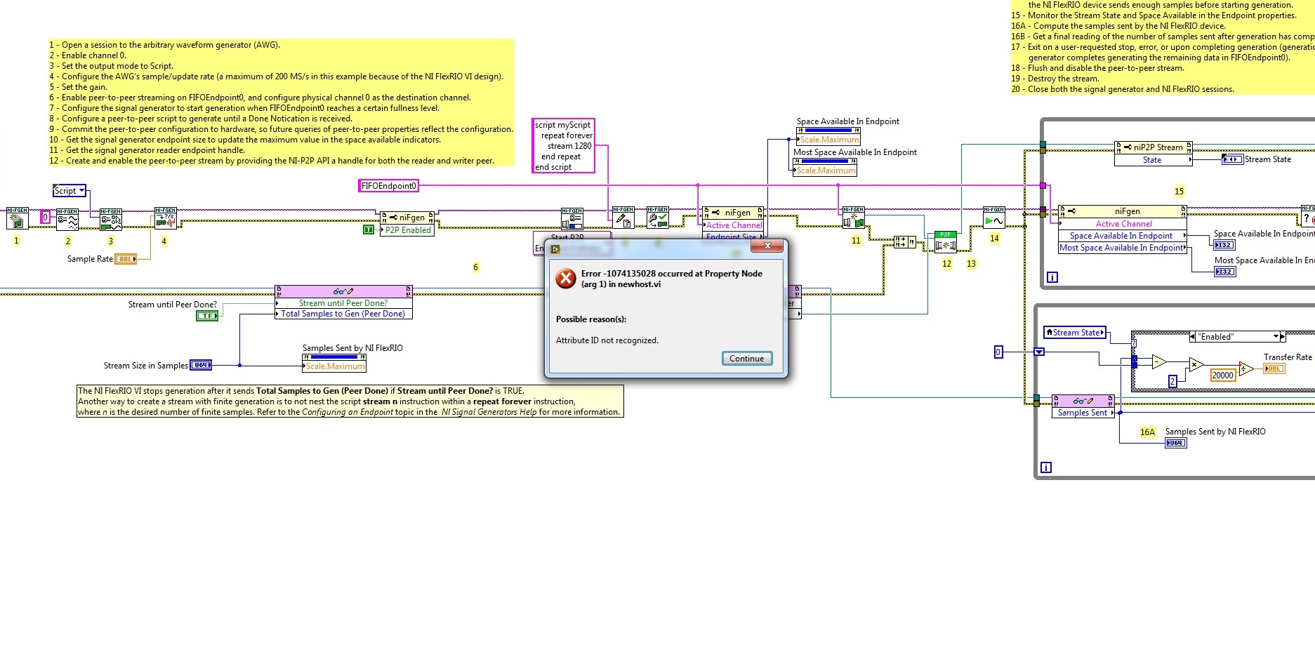
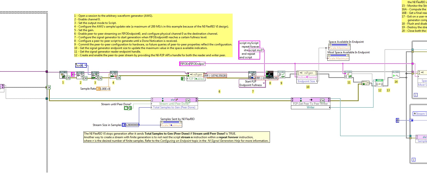
I would like to connect two devices - SMU-5451(waveform generator) and SMU-7966R(NI FlexRIO) with the P2P streaming. I want to transmit data from FPGA to the generator and I took the example of NOR-FGEN. When I started host-vi, there is an error (see photo).
What I am doing wrong?
Try to set the Active Channel property before the active P2P. Property nodes run from top to bottom, so the Active Channel property must be set before calling the property Enabled of the P2P.
-
SMU-5451. digital filter Interpolation
Hello
I use the SMU-5451 with FPGA SMU-7966R signal generator. They are related to peer-to-peer technology.
I want to use the digital filter of Interoplation, but there is a place to errors in the property node. Here is a screen of this error.
What should I do to fix this?
Looks like the 5451 doesn't have a digital interpolation filter. There is only a FIR filter on the device. You can check that this is the case and that the problem is not the use P2P when trying to run a script example that does not use P2P and setting this property. You should get the same error.
-
Interference between channels using a block of cFP-TC-120, CB-3 connection
Using a CB-3 with a cFP-TC-120 module connection block for read sensors millivolt. The sensors are pressure with an excitation of 10V sensor. Millivolt signal varies 8mv to-70mv. All have 8 differential channels wired in two of these modules sitting in slots 3 and 4, a slot 4 back on the plain. There is also the 24V in the electrical box used by two modules to relay PSC - 421 driving valves that open, leads at room temperature or in separate the empty rooms they are in slots 1 and 2. Do to the cFP-TC-120 the same and each is affected in the same way, more interference is not only between the same module 120 channels, but also between the modules! If a sensor is vacuum where the millivolt is around 7 mV reading is stable through the following conditional changes. "If a sensor is emptied at room temperature, say channel 6 and channel one is already at room temperature its reading can change by 0.25mv be affected by the evacuation of other channels. This worsens proportional number of channels is ejected by up to 0.5 mV for all other channels that are evacuated. This module is differential and each channel and the module are isolated we don't understand where or how this interference takes place. Help!
Ben,
We have done some trouble shooting and isolated in millivolts sensor signal of the NOR. We found that voltage was real and electronics is not the field point. The system runs on 24V except for sensors that have an excitation of 12v. We found that the Commons between these continuous tensions were just that, each have been shared. We have separated the Commons and vola! Perfection.
Leigh
-
DAQ interference between channels
Hello
I suffer from a problem of jamming now while I do some work data acquisition.
I'm using LabVIEW to control data acquisition system to capture the signal voltage of several thermocouples. The results of sense to me but I found, there seems to be some problems of all channels: it is clear from the joint, to find some simultaneous fluctuations on all curves (see portions of curves in the numbered 1, 2, 3 and 4).
My block diagram is also attached here (which seems to be dirty and vulgar-designed for you guys because I'm a newbie on LabVIEW)
I wonder if it is an interference with the hardware problem or a problem on my programming, and please let me know how to handle this problem to reduce (or even cancel interference).
Thank you.
Search Forum messages on "ghost".
Lynn
-
3 voltage/current measurement channels, crosstalk between channels
Hello
I am running a NOR-USB-6211 is connected to an instrument that runs labview 8.5. What I want to do, it's current 1 and 2 channels of voltage measurement channel. All are separate physical channels. I use an express VI to separate the 3 channels on the box USB-6211 and trying to draw on maps of distinct waveform stacked in a way that it respond independently (as they should be physical separate circuits). I can ALMOST that it works. I can measure the current very well. The problem is with the tensions. If I change the voltage on channel 2, channel 3 meets both equally (eg. increase 5V on channel 2, channel 3 increases of 5V); However if I change the voltage on channel 3, channel 2 does very little (such as increase of 5V on channl 3, ~0.05V increase to channel 3). Not the best result, but better than the reverse. Channel 1 is not affected by changes in voltage, but it affects the Channels 2 and 3 (current increase, increase of tension of channel 2 and 3). I have no idea why this is happening. I saw the same thing when I used only 2 channels (current and voltage). When the current (channel 1) is changed, the (channel 2) voltage changes, but when the voltage, the current does not work. There must be a problem with the program because I get the same behavior when I physically disconnect channel 3 (for example, always responds when I change the voltage of channel 2). It seems like it should be a simple installation and a simple solution, but I can't understand it.
I've included a snapshot of the program. I share the channels so I can selectively save some data in a file. I tried to simply connect the VI express to a graphic, and does not either (tensions influence each other). I also tried to replace the cluster with a table, but that did not work or the other. I tried to simulate the data with sine waves and I can get this to work without problem. I don't know what I can do.
Thanks for your help.
The f
interference of signals of high-level signals at low level is normal with inputs high impedance of a multiplexer.
put a short channel shorted inbetween and measure this also but throw the zero.
-
The sampling frequency is divided between channels USB-6211
I use a USB-6211 DAQ card. The jury is announced with a rate of 250 kech. / s. I started to take action with 2 channels and could not get the frequency of sampling of 125kHz, then when I tried to make measurements on 5 channels, I could get a maximum of 50 kHz sampling frequency. This figure of 250 kech. / s is really the sum on all channels, or is there a way to get that channel?
I have only a simple Laview program with a while loop, 1 assistant DAQ entry with 5 channels, assistant DAQ 1 exit with 1 output channel, box 'Relaxation and door' to catch a progressive input signal, a smoothing filter and graphics.
250 kech. / s is an aggregation rate as shown on the first page of the document specifications. This means that the device has a single A/D converter that is shared by all channels under analysis. According to th etime to the multiplexer and all time for the internal amplifier, your maximum rate may be slightly less than 250,000 / N where N is the number of channels.
Lynn
-
preserve the spaces between channels...
Hello world
I'm trying to extract some data in a flat file in a format that each column has start and end positions.
I am trying to trim "spaces" after each column for my requirement. My code is not preserve the
spaces between each string.
That's what I have...
But the strange thing, I found... I run the following code
and that is the preservation of spaces.declare final_str varchar2(100); begin final_str := rpad('12',4)||rpad('12',4); insert into test(col1) values (final_str); end;
Is there something wrong with my code. I need to preserve spaces after each series.
Please help me solve this problem...
Thank youHello
I did this test and works great:
DECLARE

    v_line      VARCHAR2(1000);
    FILEHANDLER UTL_FILE.FILE_TYPE;

BEGIN
    FILEHANDLER := UTL_FILE.FOPEN('EXT_FILES', 'test.txt', 'W', 10000);

    v_line := RPAD('hello', 30) || RPAD('how', 30) || RPAD('are you?', 30);

    UTL_FILE.PUT_LINE(FILEHANDLER, v_line, TRUE);

    UTL_FILE.FCLOSE(FILEHANDLER);

EXCEPTION
    WHEN OTHERS THEN
        raise_application_error(-20001, 'An error was encountered - ' || SQLCODE || ' -ERROR- ' || SQLERRM);
END;
/
Generated file:
hello how are you?Kind regards
-
Number of different characters between channels
Hi all
Is it possible to determine the number of characters that differ between the 2 strings in a varchar2 column?
My Table structure is as follows:
CREATE TABLE SPOLIGO_CDC2
(
VARCHAR2 (100 BYTE) MIRU,
FOUND VARCHAR2 (100 BYTE),
FAMILY VARCHAR2 (100 BYTE)
SUBFAMILY OF THE VARCHAR2 (100 BYTE)
COUNTRYLN VARCHAR2 (100 BYTE),
)
My task is given a value of "MIRU", for example. "'2456 c' to determine the row in the table that corresponds to the MIRU which is the closest distance of 2456 ' c ' and the value of this distance. Here the distance is defined as the number of characters that are different, regardless of the value of the characters.
So from the bottom of the values
2456a
23455
3333t
"the closest value to ' 2456 c ' is 'a 2456' and the distance is 1.
Thanks for your help,
AmyQuick ' n-sale would be a function that takes 2 inputs... the MIRU and target MIRU, compares their character
by character and returns the Distance between the two.-- I didn't try compiling this, it's just off the top of my head... CREATE OR REPLACE FUNCTION MIRU_DISTANCE ( p_val_in SPOLIGO_CDC2.MIRU%TYPE, p_ref_in SPOLIGO_CDC2.MIRU%TYPE) return NUMBER AS pos pls_integer; l_return number := 0; BEGIN FOR pos in 1..length(p_ref_in) LOOP IF substr(p_val_in, pos, 1) != substr(p_ref_in, pos, 1) THEN l_return := l_return + 1; END IF; END LOOP; IF length(p_val_in) > length(p_ref_in) THEN l_return := l_return + (length(p_val_in) - length(p_ref_in)); END IF; RETURN l_return; END MIRU_DISTANCE; /Then you can simply use something like this to do whatever you want with distances.
SELECT MIRU, '2456c' as TARGET_MIRU, MIRU_DISTANCE(MIRU, '2456c') as DISTANCE FROM SPOLIGO_CDC2 -
I try to write a control program for my reactor system, and I'm focused flow. I have the pump (0-10 VDC), but I can't figure out how to generate or modulate the voltage. I use a cRio, and I use the platform of scans, so I can't use DAQ. Could you please say.
Hello BioProcessNU,
There are several analog output modules for the cRIO. The type of module, you must use depends on how many channels you need. I've included links to some of the output modules analog National Instruments cRIO.
Here is a link to the four channels of analog output Module.
Here is a link to the 16 channels of analog output Module.
Here is a link to the sixteen channels with isolation between channels analog output Module.
-
Using SMU 6612 to measure PXI-6528 pulsewidth channel - channel is not available.
Hi all
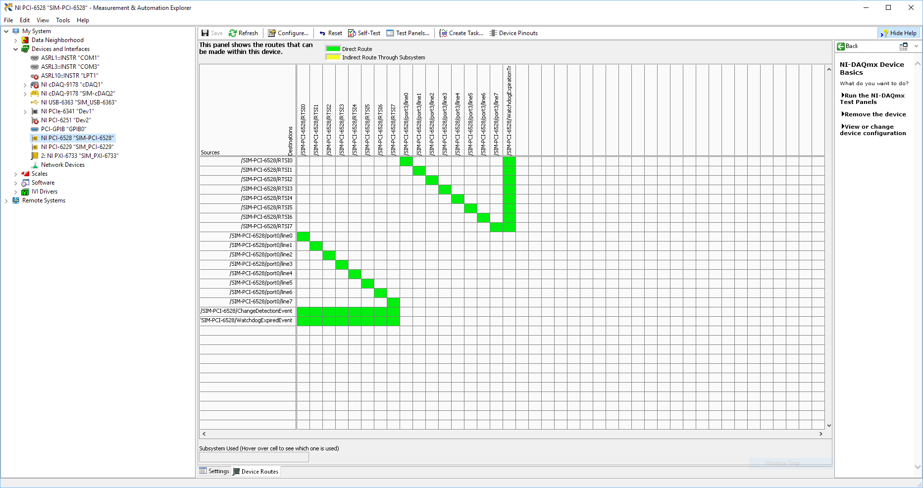
I use SMU 6612 card counter to measure the pulse width of the signals to PXI 6528 DIO card. These two cards are in the same chassis PXI (NI-SMU-1065). I could measure the pulse widths using the example LabVIEW 2013 Counter - pulse width of reading and (over) frequency example of .vi. However not all channels of the PXI-6528 map appear in the drop-down list of channels on the pulse width can be measured. Try to connect any other channel that those which are available in the drop-down list returns the error. On the PXI card port 6528 0,1 and 2 are entered ports and port 3-5 are output ports. I can measure the pulse on port 0, 3 width and line 0 port 1 and 4.
Can someone explain to me why don't see port 1 or port 2 channels in the drop-down list or force the VI to measure the width of pulse on these channels?
I can plug PXI-6528 external input channels SMU 6612 counter input channels and measure the pulse width, but if possible I'd like to avoid the external wiring between the 2 cards.
Probably not. Unless the routing plan is in fact reversed as it seems a bit sorta that. As stated on my system, you can route * of * a port of entry * to * RTSI, or you can route * of * RTSI * to * one output port. This does not make much sense to me, but that's what I see:
If the routing card * is * reversed, your only likely workaround without physical wire would be to generate impulses in question of port 3. It's pretty clear that 1,2,4,5-tetrachlorobenzene ports have no ability to interact with the bus timing, physical wiring would be the only option.
-Kevin P
-
SMU-4304 causing the ripple on the input signal?
I have an SMU-1082 chassis that contains a high-6341 and a PXI-4304 module. To check my code, I have connected the analog input (channel 0) of the 4304 to the digital output (PFI 12) of the 6341. My program VI shows a ripple of Vpp 0.2 on the analog input that I'm not using a scope.
The wiring is SMU-6341 [12 PFI, DGND]-> SCB - 68 a,--> TB-4304 [AI0 +, -]-> SMU-4304
I have attached photos of the verses reach the graphical VI. The scope is the AI0 + AI0-terminals and the TB-4304.
Y at - it a supplement on the ground that I should use, or is - this normal for the-4304 to add the ripple?
Thank you
Ron
Short answer, is that there is nothing wrong with what you see.
You have connected a digital output signal low impedance to a digitizer analog high input impedance. Since a digital signal is essentially a square of variable in time wave and square wave have edges of transition that contain information of very high frequency, you will almost always see a form of "ripple" (see animation synthesis of fourier of a signal square from this Wikipedia page ). Thus, a digital output signal is more concerned with the synchronization and the upgrade to be a square wave perfect.
In addition, you can see additional "ripple" because of differences between the SMU-4304 and the noculars that you have demonstrated. the noculars can be a combination of a bandwidth of upper entrance (which can come from various sources like low sampling frequency on the 4304 which would result in a higher frequency of information recorded by the noculars for smoother transitions to research) and, possibly, a lower input impedance (causing less, if any, the reflection of signal which would cause the ringing of the signal).
-
Unknown channel or feature name repeated
Hello
I want to connect NI SMU-5451(waveform generator) and NI-SMU-7966R(Flex RIO) with peer-to-peer technology. I took an example of NOR-FGEN, which works perfectly, but when I use it in my project there is a mistake takes place - the "unknown channel or feature name repeated" What should I do to fix this?
Hello
I saw this post in another place, and there was a proposal to reorganize the properties in your node as well as "Active Channel" is the first. As mentioned on this post, property nodes run top down and you may need to specify the channel before enabling the peer to peer. Did you get a chance to try this yet? You still see the same error?
Maybe you are looking for
-
When I open an email, 2 sections are now missing. At first, he used from, to, subject, etc.. It has now disappeared. In addition, under this judgment to the right, he used to say the answer, before, delete, etc.. He is now gone, too. I tried w/toolba
-
What happened to all my search engines? When Firefox updated to update to the latest version it wiped out ALL but two. Is NOT COOL Mozilla.
-
Cannot connect to itunes store
When I open Itunes Store, appears an Itunes U link, open it, and this message "cannot connect to itunes store. I don't know how to solve this problem, I want to watch movies and I can't. It is not connecting to wifi, it only is not that I don't sign,
-
Hello Unable to access user account! So I have to go as a guest! How can I get access in the comments, I type the password as an administrator as the user account is the administrator who is the account that I can't access! Suppose I want to remove t
-
Capture the signal micro PC line
I am aware of LabVIEW Sound screws and I used them often. My question is that if I have a line in signal plugged into the microphone port, how can I capture. There is no mic involved, just a line of sinusoidal signal. Thanks for the help,