Issue of digital overflow
Hello
Can someone well want to explain to me why I am getting this error -
{
DECLARE
P1 PLS_INTEGER: = 2147483647;
P2 PLS_INTEGER: = 1;
n NUMBER.
BEGIN
n: = p1 + p2;
END;
/
}
Error-
ORA-01426: digital overflow
ORA-06512: at line 6
Thank you 1 million.
Hello
Sri G wrote:
Hello
Can someone well want to explain to me why I am getting this error -
{
DECLARE
P1 PLS_INTEGER: = 2147483647;
P2 PLS_INTEGER: = 1;
n NUMBER.
BEGIN
n: = p1 + p2;
END;
/
}
Error-
ORA-01426: digital overflow
ORA-06512: at line 6
Thank you 1 million.
When you add the PLS_INTEGERs 2, the result is a PLS_INTEGER. The amount you're trying to do is greater than the maximum value that can contain a PLS_INTEGER, that's why you get the error.
If you change the assignment statement to
n: = CAST (p1 AS NUMBER) + p2;
you will not get this error.
If you suspect that you will get anywhere near the limit, you should not use PLS_INTEGERs.
Tags: Database
Similar Questions
-
Digital overflow in proc error
Hi guys
When running under proc I get the digital error by infinity to lineno 36... Please help me.
ORA-01426: digital overflow
Thanks and greetings
************************************Proc Code******************************************************
create or replace PROCEDURE proc_tab1 IS
V_Rlt varchar2 (4);
------------------
cursor c1 is
Select a.ref, b.key_ref from a, and b where a.ref (+) = b.ref;
------------------
cursor c2 is
Select x.id | x.dt_key, x.d_value x, y
where y.s_ref = 'ML21' and y.id = 'RT' and x.f_ref = y.s_ref;
------------------
Curr type is table c1% rowtype;
Curr c_table.
------------------
type curr2 is the c2 table % rowtype;
c2_table curr2.
------------------
Start
Open c1;
loop
collect the fetch c1 into loose in c_table;
When exit c1% NOTFOUND;
end loop;
------------------
Open c2;
loop
collect the fetch c2 in bulk in c2_table;
When the exit c2% NOTFOUND;
end loop;
------------------
because me in 1.c_table.count
loop
If c2_table.exists (c_table (i) .ref | c_table (i) .key_ref)-after concat the value length is 16
then
v_rlt: = c2_table (c_table (i) .ref | .d_value .key_ref c_table (i));
on the other
v_rlt: = "R";
end if;
------------------
Insert into tab1 (ref, rlt) values (c_table (i) .ref, v_rlt);
end loop;
end;Why not do it with a single insert statement?
insert into tab1 (ref,rlt)
select c1.ref, nvl(d_value,'R')
from (select a.ref,b.key_ref from a,b where a.ref(+) = b.ref) c1,
     (select x.id||x.dt_key key, x.d_value from x, y
       where y.s_ref = 'ML21' and y.id = 'RT' and x.f_ref = y.s_ref) c2
where c1.ref||c1.key_ref = c2.key(+);
It is not tested, you provided no examples of data...
Max
[My Italian blog Oracle | http://oracleitalia.wordpress.com/2010/02/07/aggiornare-una-tabella-con-listruzione-merge/] -
anyone else having issues receiving digital sketch, but not question to send?
I don't get the digital sketches, but can send them very well. Apple Watch has been restarted twice. Any suggestions?
Hello..
See if there is something in this article of support which may help > use digital touch - Apple Support
-
Issue of digital entry behavior
PCI-6143 with wheel wired to PFI0 & PFI1. LabVIEW pgm written in 8.5 full. Source code works well (on other Web development pages
computer with USB-6211 card) but hangs, as is eating 100% cpu time in the destination computer. This machine it must run on a LV 7.1 installed and some 7.1 executables. I installed DAQmx 8.8 on this machine with LV 8.5 support. I'm trying to run the executable on this machine that LV 8.5 is not installed.
If I enter MAX, select the card and run test panels, I get conflicting results. If I choose digital IO on both channels 1 or 0 I constantly receive all 8 lights. There is no signal. But if I'm going to count, use the trigger channels and count the edges I activity. Am I missing something? I need to remove these problems before you start to screw up my source code to find a bug that does not exist.
-
Make a comic. When you perform a digital painting, why people color all in blue before colouring with other colors?
This is a pencil sketch technique used by the designers of old school comics. It is called "no photo" or "no-repro" blue.
Blue non-photo is a particular shade of Blue , which can not be detected by the cameras of graphic arts. This allows layout editors to write notes to the printer on the print flat (the image that must be photographed and sent to print) which will not show in the final form. More than this, it allows the artists to sketch lines without having to erase after inking.
Blue non-photo - Wikipedia, the free encyclopedia
You wouldn't think this would allow digital, but this explains: http://comicsaregreat.com/video-making-non-photo-blue-pencils-in-photoshop
It is one of the Brush tool presets in Photoshop

Gene
-
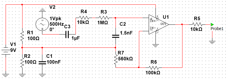
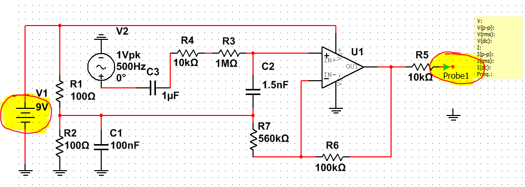
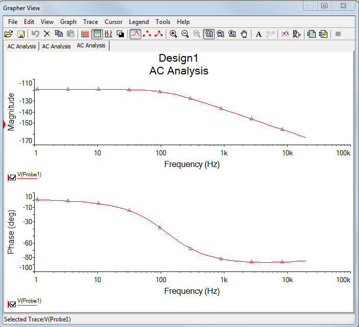
Digital overflow in the model of device in Multisim 13
I try to get the frequency response from 1 to 20000 Hz to Probe1 one I have this error occurs, please help.
Hello
I checked your circuit, there are two things need to be changed.
First of all, you connected the 9V negative VS positive + your op - am which can burn unit in real life.
Second, for your output terminal, you crashed the probe1 directly, which means that there will be no signal output at all. You can add a junction (ctrl + J) next to your R5 and remove the wire to ground to fix it.
1 to 20 kHz frequency response is shown below.
The fixed circuit is attached.
Kind regards
-
I have several numeric fields in my form. I have problems to get the numbers in the correct format. By example, if I type in 5.00 & go to the field following la.00 get stripped & shows only a 5
I tried fixing it by changing the template of validation but NOTHING I try does not work... any ideas? Thank you
Hello
Looks like you are using a decimal field, try setting the display mode:
NUM {z, zzz, zz9.99}
Hope that helps,
Niall
-
If my site is everything to lose power then I perform a failover, and then stop the primary old for awhile and then catch up on balls later? So, for example, if I finished the siwtchover and then stop and power returned 3 days later I can use raise the old primary as the day before and wait for newspapers to catch up?
If Yes, in theory can't I just do another pass after that that they sync?Hello
If you have a version of database Oracle, this passage to support.
So yes you can make a permutation, perform cutting current (or other maintenance on the primary server), and then after sync 2 databases, to make another passage to return to the normal state.Next time please give your operating system and version number of Oracle, it is easier for us.
And thanks to helpful/answered question mark.Greetings,
Loïc -
Insert + 1.7976931348623155E308 in overflow digital column ORA-01426
I'm porting an application that used a large double value of Java (MAX - 1 d = + 1.7976931348623155E308) as a semaphore to indicate a condition. I can't understand how to set the column to accept this value without giving in to the error: ORA-01426: digital overflow. I tried various details of the FLOAT (upward through 126) and DOUBLE_PRECISION and BINARY_DOUBLE and tried a trigger to use TO_BINARY_DOUBLE - all have failed. I use 11g. DB2 accepts DOUBLE as a data type and treats this value.
--------------------------------------------------------
-The DOF for Table TEST (generated from specification BINARY_DOUBLE for COLUMN1)
--------------------------------------------------------
CREATE TABLE 'DB2ADMIN. "' TEST '.
("COLUMN1" BINARY_DOUBLE
) CREATION OF IMMEDIATE SEGMENT
PCTFREE, PCTUSED, INITRANS 40 10 1 MAXTRANS 255 NOCOMPRESS SLAUGHTER
STORAGE (INITIAL 65536 NEXT 1048576 MINEXTENTS 1 MAXEXTENTS 2147483645)
PCTINCREASE 0 FREELISTS 1 FREELIST GROUPS USER_TABLES DEFAULT FLASH_CACHE DEFAULT CELL_FLASH_CACHE DEFAULT 1)
TABLESPACE 'SYSTEM '.
Insert test values (column1) (+ 1.7976931348623155E308);
ERROR on line 1:
ORA-01426: digital overflowTry this:
insert into test (column1) values (to_binary_double('1.7976931348623155E308'));Worked for me:
SQL> desc t
Name Type          Nullable Default Comments
---- ------------- -------- ------- --------
A    BINARY_DOUBLE Y

SQL> insert into t values ( to_binary_double('1.7976931348623155E308') );

1 row inserted
Published by: Marcus Rangel on sept 19, 2012 11:34
-
Laser digital lock with Labview FPGA?
Hello
Sorry to bother if you are not interested in this issue of digital signal processing. We are looking for a possible digital solutions to our problem locked frequency cavity closed-loop laser (see attached PDF file for more details). The goal is to flatten the PZTs transfer function (cancel the resonances and anti-resonances and their phase shift matching) in the frequency domain, in addition to the normal PID control. Input/output necessary voltage signals are small (we have our own amplifiers high power for the PZTs), and their bandwidth must be at least of 50 kHz (100 kHz would be optimal).
Among various OR hardware/software (DSP, FPGA, cRIO etc.), would anyone recommend a cost-effective solution for rapid prototyping?
Thank you!
I would like to look at the FPGA PXI cards nor 7854r. I rate of 750 kHz, 1 MHz AO. According to the involved treatment, you might expect between 200 and 750 kHz closed control loop. If the treatment is very intense, it's probably something less than 200 kHz.
That said, the key to these performance levels is not trivial and great care and attention to detail must be used in the coding of the FPGA.
Good luck
-
overflow in the interim results of data types
Hi all
I'm sorry, this is a very basic question...
I have the following expression, giving me an unexpected result because overflow:
D1 = RoundRealToNearestInteger (i1 * l1 / l2);
D1 is of type double, l1, l2 of type long int and i1 of the type ssize_t (on a 32-bit computer, i.e. signed int);
for example using the digital the values of l1 = 14577, l2 = 1568, i1 = 156142 I find myself with d1 being negative (-1.287554e6);
This happens if the result of the multiplication is greater than 31 bits (signed int).
In fact, I would have expected that the intermediate result would be long integer (long int int times) or double type (implicit cast), but it seems to be of type int...
Y at - it a 'rule' what type of data medium is used and can be expected in such a case?
BTW, I am aware that I can avoid the problem by reorganizing the calculation: l1 / l2 * i1

Thank you!
Wolfgang,
C basic rule for arithmetic calculations, is that all the items concerned are promoted to the highest current type. Thus, for example, that if you multiply an int by a tank, the tank is first promoted to an int, then the multiplication is performed. (This is why you must explicitly cast a variable to a double - the compiler then automatically will encourage others to double). In your example, the largest involved type is a 32-bit int, (even the long type) so this is what would be used for calculations. This gives a digital overflow, a standard C compiler just do not know. As the function you use takes a double parameter in any case, the final result of the calculations all over will be converted twice, but only after integers was carried out. The right solution is to first l1 or i1 to a double cast.
(Note: there is an ambiguity in the ANSI specification on how many parameters are encouraged.) Some interpretations are that all the parameters in an expression are converted before the calculations are made, other whole-hearted are that only the two components of a single operation are put in correspondence. So, in your example, it would be unwise to simply throw l2 duplicate - it may work, but it is not guaranteed to be portable between compilers.)
JR
-
Hello, I recently won the myRIO, but when I try to install it, I get this error and it is said that some software is not found, also seeing myRIO of State flashes twice every few seconds.
Dranoel,
According to the manual of myRIO ( http://www.ni.com/pdf/manuals/376047a.pdf ) if the LED flashes twice, it means that the device has detected an error in its software. You need to reinstall the software on the device.
For this, you can follow the instructions on the link below to do this:
http://zone.NI.com/reference/en-XX/help/373925A-01/myriohelp/myrio_advanced_config/
The software recommended to install in your myRIO is myRIO LabVIEW 2013 Module Patch f1, here is the link for the download:
http://www.NI.com/download/LabVIEW-Myrio-Toolkit-2013/4469/en/
After some research I found that this patch difficulty this specific issue ( http://digital.ni.com/public.nsf/allkb/437F6538BE9B301486257C0C0075FD18?OpenDocument ).
After you install this hotfix, use the Update Service OR to ensure that the software is updated. Only after the necessary updates I recommend that you follow the steps in the first link.
I hope this will solve your problem, let me know if it worked.
Best regards!
Here is my answer in Portuguese:
Dranoel,
Of acordo com o manual myRIO ( http://www.ni.com/pdf/manuals/376047a.pdf ) is o CONDUIT esta piscando duas vezes, means that o device detectou um erro em seu software. Precisara Voce software restore o no device.
Para isso, você pode seguir as f no link abaixo:
http://zone.NI.com/reference/en-XX/help/373925A-01/myriohelp/myrio_advanced_config/O software recomendado para instalar no seu myRIO e o LabVIEW 2013 Myrio Modulo f1 Patch, aqui esta o link para o download:
http://www.NI.com/download/LabVIEW-Myrio-Toolkit-2013/4469/en/After some pesquisas had achei esse esse problema specific will patch than (http://digital.ni.com/public.nsf/allkb/437F6538BE9B301486257C0C0075FD18?OpenDocument)
Instalar esse patch after use o NI Update Service para ter certeza that os software are atualizados. Only apos as well EU recomendo seguir os passos do primeiro link atualizacoes.
Espero that isso will go resolver o seu problema e so told me to work.
Abraço!
-
Need help with GetScaledPanelDisplayBitmap
I'm trying to use the GetScaledPanelDisplayBitmap() function to generate some clips from a display of a Panel, but I have serious difficulty with it. Take the following code segment, applied to a panel size 1200 x 800 (W x H):
height = - 1; width = - 1;
GetScaledPanelDisplayBitmap (panHan, VAL_FULL_PANEL, MakeRect (0, 0, 300, 400), height, width, & bitmap);
GetBitmapData (bitmap, 0, 0, & x, & y, 0, 0, 0);
This works as expected, returning a clip actual size of the selected area. I need this clip down to generate the thumbnails, so I was set the values of height and width according to the function of the scale. Then:
height = 300; Width = 400;
GetScaledPanelDisplayBitmap (panHan, VAL_FULL_PANEL, MakeRect (0, 0, 300, 400), height, width, & bitmap);
GetBitmapData (bitmap, 0, 0, & x, & y, 0, 0, 0);
gives the values x = 133 and y = 113, in agreement with the calculation (x = width / PANEL_WIDTH * area.width) as described in the help of the function. So far so good. But when I step up certain values, I have problems. It works well:
height = 300; Width = 400;
GetScaledPanelDisplayBitmap (panHan, VAL_FULL_PANEL, MakeRect (0, 0, 800, 1200), height, width, & bitmap);
GetBitmapData (bitmap, 0, 0, & x, & y, 0, 0, 0);
give the expected value of 400 x. But when I change the width of the Panel at 2400 and everything else will remain the same, I now get a width of 235, not 200 waiting for the calculation. It gets even worse: with small values, the offset of the area of selection (the (0, 0) in the MakeRect) makes no difference to the final result. With higher values, zero offsets are beginning to have an effect on the size of the final bitmap. In other words, the calculation breaks down completely for larger values and I think it's impossible to calculate the scale factors.
At the beginning, I have although the size of the actual visible screen (on a 1024 x 768 screen) having me an impact, probably because of the area of selection cutting, but the example 1200 x 800 which really worked OK refutes this. In any case, I think any clipping to reduce the final size, but it's larger than expected. I struggled with this for quite a while now - I just can't understand what is happening. Can anyone shed light on what goes wrong with the function/calculation for large values? (Digital overflow?)
Mike
Roberto,
I have may reproduce symptoms of Mike, using your code. BUT only when I try it on a laptop (1024 x 768 screen). If I try the same code my desktop computer (1920 x 1080 screen), I get the same results you - it works fine. Until, that is, I increase the width of the Panel at 4800, when the non-linear problem appears on this machine as well. I can't understand it.

Mike,
There is a solution. It's a bit messy, but if you use GetPanelDisplayBitmap (), and then apply the new bitmap to a new control to the canvas (identical to the bitmap image size), you can then use GetScaledCtrlDisplayBitmap () to set the desired scale. This does not seem to suffer the same problems.
JR
-
I have a question about a FPGA project I'm developing.
I use a digital RIO NI PCI-7813R, objective and Module FPGA 8.6.1
I implement a SPI bus, master.
I use a state machine in a single loop of Timed Cycle. (about model on one of your examples IP)
I'm running the loop at 20 MHz, which produced a clock of 10 MHz SPI bus data.
I send you the data in 8-bit bytes delivered by a FIFO of the host.
Similarly, I return data bytes of 8 bits of the host by using a different FIFO.
I have no problem sending data, generate all the select chip and data impulses on my desired clock edges.
It's manual clean and perfect as seen on a scope / Logic Analyzer.When I read data from i/o pin however I have found unexplained behavior.
It is this: the data seem to be trolling by two read operations.
When I read the axis of I/O data to the specified limit of the clock that I generate.
I found that the data were two bits shifted to the right, i.e., deferred, one on the scope / Logic Analyzer.
I did a work around by two pins I/O multiple read operations in time of the gap between the data bytes.
There are no generated clock signal and no data valid on the I/O pin at the time of these two read operations as testified to by the scope.
And now the data received matches perfectly to the one sent.
I can only assume that there is some kind of pipeline or delay inherent in the IO read operations. (at higher clock rates)I suspect that there may be something in the optimization performed in the compilation of the structure of the SCTL the cause.
I had found it, sometime before in my development, that data has been little offset from 1 only one position.
I think it was at a slower pace of global clock.I also ran the same state machine in a classic logic expect everything in a loop with an FPGA, to produce a much slower system
and I found that there is no delay at all.I don't see anything in the configuration i/o pins that can affect this. (I turned off arbitration)
Similarly, I don't see anything in the documentation that could refer to this behavior.
8.6.1 of LabVIEW FPGA Module Known Issues (http://digital.ni.com/public.nsf/allkb/F6B5DAFBC1A8A22D8625752F00611AFF)I'm about to use and deploy the code with the solution because it seems to be reliable.
But I am at a loss to explain (in my documentation of the code) why it is necessary
or how to solve this problem if the compiler changes.
Do you have any suggestions?I think that what you run is that the number of sync records used with the digital I/o. If you right-click on the I/O item in the project and select the property page, you should see an option for number of registers for output and output enable synchronization. These settings are global settings for this I/O item that will be the effect on all nodes of the I/O writes to this point of I/O. Similarly, if you right click on the e/s on the schema node and select Properties, you should see a setting for number of registers of synchronization for playback. This setting is specific to this instance of the node for this element of I/O and can be configured differently for each node in the diagram. The effect is that each sychnronization registry will delay this beating of a clock signal. These records are inserted to prevent the problems of metastability and ensure that you always have signal levels valid when the IO is sampled on the edge of the clock. There is a problem whenever the producer and the consumer of the signal are market off different clocks, or at different clock rates. If the external device drive your digital inputs work synchronous clock you are producing, you can eliminate the registers of the synchronization. However, you must perform an analysis of delays in propagation of the signal between the two devices and make sure that all the settings and hold times are always met before. In the end, I think that the easiest and most robust solution will be to compensate for delays in sync in your code as you do already. I hope this helps clarify things.
-
Windows Media Center requires an activation code.
Hello all. I'm having issues activating digital cable on a windows machine 7.
This is the system in question:
- Shuttle XPC
- x 64 athlon dual core Ghz 2.24
- 4 G of RAM
- Windows 7 pro
- ATI USB Open Cable Tuner with comcast mcard
So I ran the digital cable Advisor and it goes very well.
I put the mcard in tuner and plugged. All LED to the Greens and I have it plugged into the computer. The tuner installs and I check in via the interface, just fine.
I called Comcast and had them activate MasterCard. I waited a day and then tried to activate digital cable and he repeated to me that I need a key, it should be on the installation CD or something. In aprevious post, a person indicates that it must be equipped by the cable operator, but it is clearly a PID Ms. I'll try to call comcast again later, as I'm not at home now, but any input would be nice.
I'm actually confused do not know at this stage and really get a sense of the place where from here.
Thank you
Chris
Very well! I got it! I reinstalled x 64 and re run DCA in windowed mode and it works! RECORDS OF HBO, HERE I COME!
I'll write an article with all my woes and link for it here. Thank you guys!

Maybe you are looking for
-
Re: Error during the creation of a satellite L300 recovery disc
I tried to create my on my new laptop L300 recovery disks. While creating the disk I get the following error:Cannot read the following F:\ZZImg|09115XSP.swm file (error code: 020150-20-00000000). Anyone know what this means and how to fix this? I hav
-
Iomega IX2-CloudEdicion on the problem of network MacOSX El Capitan with index Spotlight
Hello! I have a big problem with my Iomega NAS. MacOSX 10.11 El Capitan, I run, I try to look for documents on my NAS storage and takes a long time to find and can find all the documents. I try to re-index the volume but still the same... I activate
-
How do I check spelling in Outlook Express
I have Outlook Express 6, Word 2010 and Windows XP, but my spell checker for OE is grayed out and I can't use. How can I check the spelling in OE?
-
updates for windows 7 Home Edition problems
I have a HP Pavilion computer processor AMD Sempron 140 2.70 GHZ, 3.00 GB, usable 2.75 GB installed memory. Type of system 64-bit operating system. Windows 7 Home Edition, service pack 1. My problem began two months ago, every time that microsoft win
-
Not me works el sonido del ordenador
not me works el sonido del ordenador