LabView Thermocouple temperature readings
I use the SCXI-1001 with SCXI-1102 and SCXI-1303 (LabView 8.2) in record temperatures of thermocouples type k. My problem is that the temperatures that I see on LabView are off by about 5-10 ° c. AND they stray +/-10 ° c throughout the day. What I've read, I think that this could be linked to the CJC. Right now, I just CYC Source set "Permanent" with a value of "25". I can make adjustments to it to help with the lag, but the drift just of temperatures throughout the day and the readings are again incorrect. The room temperature changes somewhat in the region where I have this configuration, and drift in temperature seems to be linked to that. For any help or suggestion would be appreciated. Thank you.
Hi Zawer,
Your SCXI-1303 module has a welding temperature sensor cold precision thermistor, so the 'Integrated' parameter must be supported. Try resetting the 1102 able and Automation Explorer, then restart LabVIEW. Is thrown this error yet?
Tags: NI Software
Similar Questions
-
Hello
I want to trace the temperature change indicated by two thermocouples (that are connected to the analog input Module NI DAQmx) with repsect in time (two curves for thermocouple 1 and 2) on a graph unique waveform. Two thermocouples are connected to two channels separated in the module. Waveform graph must be shown in the before, but also exported to a worksheet.
I have grouped the entry of time and separately two thermocouples temperature readings. and then tried to build a cluster. However, I get an error message. Please see the attached VI helpme to achieve the desired results.
Thank you
Josée Vilas V
-
Very high readings of temperature CPU of the Mac Pro 8-core 2007
I have a Mac Pro 1.1 updated to level with two Intel Xeon X 5365 CPU and firmware 2.1. The system has worked very well for months. However, I'm worried about CPU temperature readings. Assuming that the readings are correct, I have no explanation for the difference in typical 30 degree Celsius between the processor and the heat sink.
Is it possible, that the CPU exceeds their life expectancy?
During a stress test, I can see the following typical readings:
CPU core 87 C / 189 F
CPU a heatsink 58 C / 136 F
B processor 91 c/196 F
CPU radiator B C 59/138 F
I use new thermal paste Arctic MX-2 and tried various measures, including polishing of the surface of the CPU and the heatsink using sandpaper grain 1000. Nothing has so far had no effect on temperature readings. There should be enough good contact between the heatsink and processor during the installation, because they stick well enough to remove the heatsink again.
Max TCASE. According to the operating temperature -1333 http://ark.intel.com/products/30702/Intel-Xeon-Processor-X5365-8M-Cache-3_00-GHz-MHz-FSB is 63 degrees Celsius.
According to http://www.intel.com/content/dam/doc/design-guide/5400-chipset-memory-controller-moyeu-guidelines.pdf the Quad-Core Intel® Xeon® 5300 series include a function of on-chip temperature sensor. The heat sink provided by Apple has a temperature sensor, which seems to be fixed directly on the coper plate that touches the CPU head spreader.
Given the following quote from the same document:
TIM's performance is sensitive to degradation (e.g. breakdown of fat) over the life of the processor because of the temperature of the phenomena of cycling. For this reason, measuring of the processor given TCASE value can decrease over time according to the type of material of TIM.
Anyone know if the IHS on the CPU is soldered or whether they used the thermal paste between the IHS and the die of a CPU? In the case, perhaps it could explain the current temperature readings.
Any ideas? Thank you!
Your temperatures look a bit high, but not outrageous. The temperature measured on the Silicon of heat will be always higher than the temperature measured on the radiator. That's what the radiator is supposed to do, leads away from the heat to the fins, which would measure even more cool.
Your Mac allows to adjust speed of the fans to the top in a loop of feedback, founded the temperature of these measures. You can place a floor under your minimum speeds of fans. This can be done with the tool similar to some tool you already use, like the SMC fan control.
If the processors to exceed their safe operation temperature, your Mac will perform a sudden uncontrolled power off.
-
Configuration of thermocouple to MAX
I'm in the process of upgrading an ancient system of labView to a new beautiful brilliant (v4 for 2009) but I encounter some problems of setting up my thermocouples.
The old PC them works very well and becomes sensitive readings - a new is not so happy. I use the former Council of SCB - 68 even for both and have just upgraded the DAQ (now a PCI-6221) card and the PC.
MAX and LABView can read very well the thermocouple voltage and voltage correctly responds to changes in the thermocouple temperature (ambient 1.38v and response is 50mv/C) - However, when I try and tell him it's a thermocouple it tells me that the room is a constant of 398 000 degrees! This reading shows no response at all to the variations in temperature of the thermocouple.
I've got the thermocouple connected to AI2 on pins 65 and 31 as MAX connection diaigram seems to suggest. This is how I wired it upwards, or is it my setup that does not?
Thank you in advance for your help!
Pete
Heh, I solved. Unfortunately, it was me be stupid all along.
The installer of the equipment that we measure is such that the thermocouple is about 10 ft away from the computer. Its attached to a wire that goes behind some cabinets and then to the back of the PC.
When I plugged the thermocouple directly in the room it worked fine - exactly as it should. Then when I put it on its extension cable there nuts again. I pulled out the wire behind the cabinets and carefully hidden to halfway along the wire is a housing of the amplifier. He never FAILED me to check the thread - I guess that even if there was an amplifier I wish that it is at the ends! I feel that this kit was concocted by several people talked to each other, so it does not surprise me none. I guess that, in the old VI, somewhere, there must be a correction factor hidden somewhere.
Thanks for your help guys - you definitely guided me in the right direction.
Pete
-
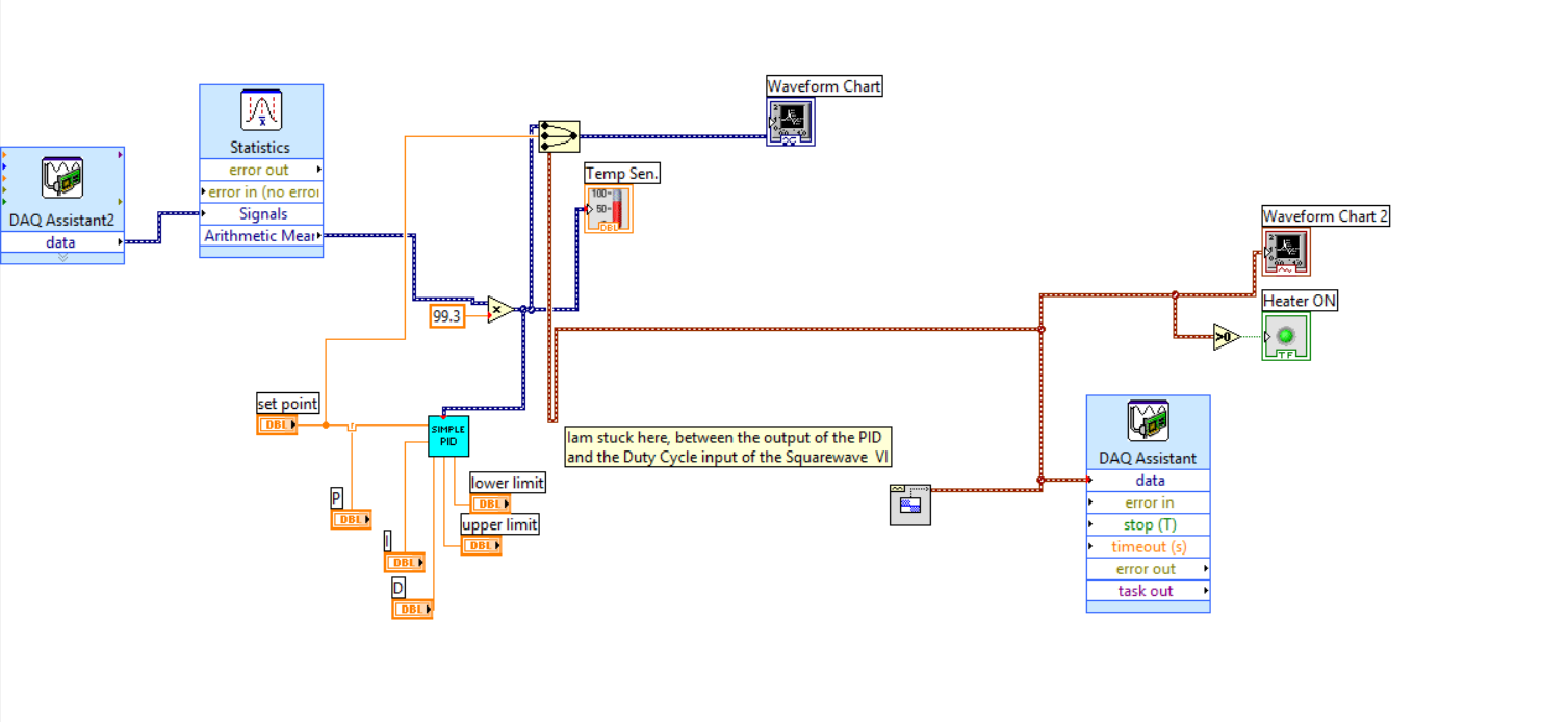
Hello everyone.
IAM working on a temperature of Labview control program that uses a controller of PDI, a radiator, a read thermocouple temperature.
IAM able to read the sensor and I think that I managed to implement the PID as well.
What I have to do now is to convert the output of the PID in a Cycle of use appropriate in % to enable/disable-energize a Solid State Relay for the power supply of heating.
To generate a square wave, I thought using the Waveform.VI of the place. (see image below)
The output for the PID is in the range 0... 5 v so I guess I do this output to scale in a way?
Thanks in advance for any help,
Best regards
Michael
I have not seen that VI PID single within a certain time, and if you have access to the PID toolkit (now included with versions of LabVIEW non-Base) you must use that one instead. In both cases, however, the limits of output are set by entries in the VI - in your case, the 'threshold' and controls 'Cap '. Change these so they are 0 to 100 and then use the output of the cyclical report.
-
Thermocouple configured in module module-9221
Hi all!
Nice day!
I try to configure thermocouples type K 6 through the NOR-9221 analog input module and chassis cDAQ-9174. I'll be able to get the direct temperature readings outside this module not being a thermocouple module? Otherwise? Please suggest me how to get the temperature for this add-on module-9221 directly! Quick help will be very appreciated!
Best regards!
Tajim
To build on what the broken arrow, the 9221 is really not at all optimal for measurement by thermocouple. Most of the measures by thermocouple are between 0 to 80 mV. The module 9221 is a 12-bit with a range of ±60V module. The width of the code for this module is about 15 mV and your accuracy is 156 mV. All your thermocouple readings will be lost in the noise for this add-on. I would recommend the 9211 or the 9213 for measurement by thermocouple, because each has CYC and is specially designed for thermocouples. If you want to try an external amplifier, which can run, but you will probably need something that can amplify from 0 to 80 mV to 0 - 60V.
Kind regards
-
Two measures of different thermocouples 1303
Hi all
I use a SCXI-1303 module and a module SCXI-1102 and SCXI-1000 chassis. The plan is to measure the temperature using thermocouples type T. 1303 modules (I have 3 of them) are completely new, and I pulled out of the box and put them on my 1102. I was testing my thermocouples to ensure they all worked when I noticed a difference in temperature between some of the thermocouples. When I started using AI16 (0-15 was already in use) temperature readings began to appear about 4 degrees below all other temperatures. Most of the thermocouples read 21 c, which is good, but those channels AI16-19 (I'm not plus far only 19), have been reading of 16 C. So I swapped the thermocouples, who had read the right temperature (from AI15) set AI16 and he showed the same offset of 4 degrees, so should not be a thermocouple problem. I put the 1303 on another module of 1102 and I swapped the 1303 modules, I had the same problem each time. The polarization resistance came in 1303 modules, so I have not tested with them. I get the same temperature difference using "integrated" and "constant" for the source of the CJC. I can hardly believe that it's a hardware problem, scxi-1303 1102 both had the same result. So I was hoping there is something else here I'm missing. I looked in the forums and not found anything quite like my problem. I read the manuals but have not encountered anything that would explain this.
Please let me know if you need more information,
Thank you
Jim
Well, I feel stupid. When you use the wizard daq, you must specify the type of thermocouple for each channel. I've had several channel sent to the type of thermocouple wrong without realizing it. Switching the appropriate type, made them of course work.
Heh, sorry for the useless post

Jim
-
Reading of temperature for the use of Thinkpad T510
Hi all
I have a question about the standard temperature / acceptable range for computers thinkpad t510 operation. My setup is currently my t510 is connected to an external monitor, speakers, keyboard and mouse. Therefore basically a desktop computer except using the innerds of the laptop as the "heart" of the system. My power manager put the CPU to adapt. The temperature readings that I get for the processor and the motherboard download the program called of Piriform Speccy are on average 60 to 61 degrees C. I wonder if it is within the normal temperature of operation for the laptop and if it is acceptable. What is the temperature not okay and why it is so high, it's that I use external references. Also, I even use heavy workload for the laptop and more for the web, browsing and listening to music and work on documents / spread sheet so basically, office work.
And finally, the problem of temperature would resolve if I would in the future to get a computer laptop w530 since these laptops are more "powerful"? Or is that evil and the temperature is normal.
Thanks in advance for answers
unit88888888 wrote:
The temperature readings that I get for the processor and the motherboard download the program called of Piriform Speccy are on average 60 to 61 degrees C. I wonder if it is within the normal temperature of operation for the laptop and if it is acceptable.
Yes ~ 60 ° C is quite normal. I would get concerned if temperature readings consistently exceeded 80 c or if the fan was constantly. Otherwise you will see the temperature fluctuates as activity processor and graphics vary.
-
I7-920 CPU temperatures range between 54 ° C and 100 ° C.
Hello.
I hope someone can advise me here.
My hearts of the i7-920 processor reached during the analysis of my PC with Windows 7, Microsoft Security Essentials, the following temperatures without running other applications.

My BIOS showed the following readings.
Discount on zero case status open
[Disabled] Case opened Yes VCore 1.252V DDR15V 1.536V + 3, 3V 3.296V + 5V 5.080V + 12V 12.112V The current system temperature 41 ° C. Temperature identified 92 ° C Current temperature of health maternal and child 48 ° C. Current CPU FAN speed 2368 RPM Current speed of FAN2 SYSTEM 0 RPM The current ELECTRIC FAN speed 2636 RPM Course SYSTEM FAN1 speed 3426 RPM My PC has 6 fans:
1 fan on the CPU cooler intel standard.
1 fan at the top of the case,
1 fan on the back of the case,
1 fan on the front of the case to 5 hard drives,
1 the power supply fan, and
1 fan on the graphics card.
They are all clean and running.
With only currently running Firefox, my CPU temperature readings are as follows.

Should I be concerned about these temperatures?
Yes.
Cooling is quite inadequate. Time slowed by the 920 stock speed should not be more than around 30-35 degrees C and under load not more than 65 degrees. Stock cooler can add a few degrees, because he is not good at all, but there is also an insufficient air flow in the case of cause these absurd time. It is very detrimental to the longevity of the CPU.
I suggest that you get a good third-party CPU cooler with push-pull configuration, like CoolerMaster, Noctua or Prolimatech and good thermal paste, correct the internal airflow with cable management good or get a larger case. Report your progress.
-
Dear all!
I'm looking for help on the NI USB-6008 case. I'm putting in place 4 K thermocouples using this USB-6008 4-channels. I made an express VI in the Labview 8.5 and I have installed all these 4 channels in this VI. The VI is attached for your review! Come to the problem! I get strange readings of these 4 channels even if I have no thermocouple connected to the terminals with respect to this USB-6008. Please help me and explain what is happening? Why am I getting these strange temperature readings while there is no connected thermocouple?
Greetings to all!
Tajim
Dear all,
I'm sorry for not attaching the screenshot of this configuration! Here, it's this time!
Kind regards!
Tajim
-
Simultaneous inputs from different sources
I am creating a resistively heated wire heating unit. What I had planned to do, is to connect the wire to a programmable DC power supply that I would link to a USB-232 (Jack single port RS232). I also want to integrate some temperature readings of a thermocouple placed near the heating unit. I would connect the thermocouple to one of the analog channels of a PCI-6259 (M series). Already, we have the PCI-6259 (and the connection block), but so far have not bought the power supply DC or USB-232. Until we buy these, anyone know if this configuration is still possible? I wasn't sure if it would be possible to have two separate entries, enter LabVIEW from two different sources (USB and PCI) simultaneously. Also, are there any other ways I could do it easier? I looked into analogue programmable power supplies DC, which I was in control of the PCI-6259, but these seem to be still more expensive than RS 232 controlled ones.
Thanks in advance
Hi Stephen.
You can have devices to multiply the input/output, how you design your code will detemin how well that work. The USB port can produce at the same time as the PCI card is entered. The channels you create what you will specify aquire and when.
What is the programmable DC power you are looking at?
-
Is there a single SCXI module adapted to the entries for mixed probes?
I'm trying to set up an SCXI system to receive signals from a number of different types of sensors. I have a large number of thermocouples for which I decided to use the SCXI-1102 module. I also have a unique pressure sensor (unknown spec so I'll assume type of strain gauge), a unique accelerometer (once again, unknown technique) and possibly a few tensions ahead right (unknown County and spec so assume - 10 v to + 10 v Beach max).
Is there a single SCXI module through which I can acquire voltage signals, accelerometer and pressure sensor? Or maybe just use 2 modules instead of 3 if I have a SCXI-1530 for my accelerometer and an another module for the tensions and the pressure transducer? I was watching the module SCXI-1121, which looks promising for the tensions and pressures but then was unsure as to what block of connection to use for the combination of signals (possibly, I could live with a - 5V to + 5 v range if necessary).
(Additional info: I use TC-2095 blocks with my SCXI-1102 module, can not really use spare entered on those voltage inflows).
Thanks for any help.
CASE NO.
It's expensive,
Thanks for your inquiry. You obviously already did a lot of research on this issue. I fear that it is unlikely that you will be able to use a single SCXI module to perform any function you listed. Necessary accelerometers such air conditioning specialist, it will take a module - as you mentioned already, something like the 1530 (4 channel accelerometer input module) would be ideal.
However, you have a number of different options for the pressure, voltage and temperature measurements.
For example, you could buy a mudule 1520 for your measurements of pressure and then use a generalist 1102 b for voltage and temperature (need you the connection block insulated from 1303 to condition the thermocouple readings... and work around the CYC technology for pressure readings).
Or, you may use the module thermocouple 1102 for your temperature readings and then use a 1102 b to take pressure readings and the pressure. Of course, that would require making your own bridge to the pressure sensor configuration, but this should be pretty easy.
Before making any final decision, I would recommend that you call your local branch of the NC and speak with a sales representative. Perhaps, a member of the sales field staff might actually come see discuss you it face to face.
Finally, it looks like you have a number of ways relatively high for some of your reading, is why you decided to use the SCXI platform. I was just wondering if you had considered compact DAQ (cDAQ), which combines the DAQ hardware with signal conditioning. Top spec, ease of use, lower number of channels. Swings and roundabouts I guess.
I hope this has been of some use to you.
Best wishes
-
Problem with the generation of two internal counters pulse trains
Hello
I do a control of temperature for two heaters, OR 9472 (output module digital), NI 9271 (RTD for measuring temperatures) and cDAQ-9174 chassis. So, I use the internal meter NI 9174 to generate two pulse train on the outputs (I tried with both cases-> pulse continuous and finite). Before that, I have two separate PID.vi, in which each sent the percentage of cycle of obligation for the two tasks of pulse generation (I configured these tasks with the physical channel cDAQ1Mod1/ctr0 and cDAQ1Mod1/ctr1). The problem is when I run the program, because the application initially worked fine, but after a few seconds the communication between the chassis and the application is not respected (no error message, but the external LEDs on the NI 9472 module had been disabled and stopped too NI 9271 module temperature readings). Then I tried to stop it with a 'Stop' button, but nothing happens. After, I abandoned the race and still nothing happened. So, I finished the Labview program with the Task Manager and a message appeared "reset VI: xxxxx". Finally, I have to restart my computer to run the program again. Can anyone help with this please? If you need more information, let me know.
Kind regards
Hi Luis,.
I have the error cluster connected. But I solved my problem in a different way. I don't know why, but when I configured my RTD module with the DAQ assistant to test some of my design in a new file in VI, the RTD module works fine, but if I copy the entire program logic (include my DAQ assistant) back to my main VI folder and run the application, only for communication between my DAQ hardware and my software works there shortly. So I solved my problem set up any device or module in the same file from the application again and problem disappears.
Thanks for your help.
Luis C.
-
Two background colors for the same waveform graph
Hello guys!
I have a question for you: I am a new user of labview, so please be nice!

So here's the deal: I just created a thanks 4 thermocouple temperature registration program.
In real time, I then have a waveform graph 4 curves as soon as I start my program. And in my program, I had a button that allows me to record the temperature in a file for a period of time at a certain frequency.
So, what I have is: I got my chart of waveform with a black background for example, and once I pressed the button, the background color will be changed automatically to highlight the part of the graph where the record occurs, then the background will return to the black after finished recording. In this way, on the same graph, I could say that registration took place from here to there by looking at the graph. I have two different background on the same graph.
I don't know how to change the background of a chart using the property node, but is it possible to do what I want?
I hope I'm clear. Otherwise, feel free to ask me for more details... I might post my vi if necessary
See you soon
Well, I know this is not exactly what you want to do, but you can try the following.
Change the color of the line on the chart when recording occurs.
You could therefore have a red line, then press on save, then it turns blue, then back to red.
And when that is confusing since you have 4 different lines on the chart 1,
You can change to a red line and a dotted red line, for example.
Would that be acceptable? If so, I can show you how to do this.
-
Problems with USB-6218 in DAQmx connection diagram
I use MAX to implement the tasks of measurement thermocouple for part of our engine Diesel DAQ. It's a simple enough part of DAQ - read in the thermocouple temperature measurement and then draw. The problem that I am running is with the wiring diagram. Looking at the USB-6218 casing, it is labeled for the analog inputs, but when I go back the stitching in the measurement and Automation Explorer (photo attached), it shows that the pins are marked differently.
For example, that I choose to have a thermocouple (two sons) in analog input 0 (ai0). The diagram shows that I should connect the two wires of thermocouple to channels 15 and 16 which are AI0 and AI8, respectively in the pinout diagram. Then say I assign another thermocouple with 8 analog inputs (ai8), he tells me to write the two wires of thermocouple to 16 and 28 channels which are AI8 and AI GND, respectively on the pinout diagram. This is great except for the fact that both ai0 and ai8 use the same channels on the DAQ card.
I get the same thing when I select ai1-> CH 17 (I 1) and 18 (AI 9) CH then ai9-> CH 18 (AI 9) and 28 CH (AI GND). Channel 18 (9 analog input) is used for both thermocouples.
No idea as to why LabVIEW is bunk of the analog inputs?
No, you cannot change the pairings and as shown in the picture, ai0 and ai8 are right next to each other. Can't be more close to everything.


Maybe you are looking for
-
Cannot get the home page of firefox on my computer
I get the start page. I want to be my firefox home page
-
Hi, I keep getting a pop up message when I plug my laptop adapter lately. He said, "for maximum output to connect a superior smart adapter of capacity." I use the original AC adapter came with my laptop, which is 2 years old. Is something wrong with
-
Peripheral Bluetooth is not listed in Windows mobile stuff Center
HelloI installed the latest driver Bluetooth of Vista on my laptop (426 P100) and I have not even a connection with my cell phone. Unfortunately I'm not able to use this connection with the Center for devices windows mobile. If I click on the Bluetoo
-
Hello I use the IMAQ flatten image for the vi string to flatten an acquired image and write it to the binary file. Later, when I read the binary file and try with it chain unflatten, I get an error message: 74 error to Unflatten channel into frames g
-
Hi, I accidently cracked my screen A1. I'll try to find on the same screen for the replacement online, but just could not find it at all. Help, please. Thank you.