LabVIEW .vi implement
I suppose you want the Subvi front panel to pop up?
If so, have you tried this:
Open the Subvi and access properties by accessing the file-> VI properties and choose the appearance of the window category. There, if you customize, you will see an option to "see the front when it is called. Don't forget to check this.
In addition, if you want the Subvi is displayed when you press the button, then put the Subvi in the case of 'Real' of the structure of the case.
Tags: NI Software
Similar Questions
-
How can I implement this formula?
Hello, I use labview to implement the formula in the image;
x with i, is a particular element of the nx1 range...
What should I do?
I don't think that you still need a loop FOR. try this:

-
Where are the UART pins on sbRIO-9627?
I'm new to the SingleBoard RIO and I need 5 UARTS, but I can't find RX TX PIN. Where the pins are located?
Data sheet: http://www.ni.com/pdf/manuals/375466a.pdf
Product page: http://www.ni.com/white-paper/52801/en/
RS232
Edge (Total) = 2 (6)Page 42 of the manual to the user began documenting how to expose additional UARTS.
http://www.NI.com/PDF/manuals/375466a.PDF
The UARTS are implemented in the FPGA, so the TX and RX pins can be routed to the FPGA DIO lines. Which is defined via the sbRIO generator tool CLIP installed with LabVIEW and implemented by selected a half TON plugin CLIP in the LabVIEW project.
Page 24 of the RMC design guide also gives more details:
http://www.NI.com/PDF/manuals/375536a.PDF
In addition, this presentation of NIWeek walks through the design process RMC and SW tools for configuration of devices, such as the UARTS.
https://decibel.NI.com/content/docs/doc-43347
Kind regards
-
Hello
I have a list of memory addresses and use Moveblock to get the values (which is a 640 x 480 arrray 2D in my case). That's just fine until calling Moveblock multiple times (for example using different memory addresses) for all my paintings 2D (120 tables). The problem is that it takes a few tens of ms FRO Labview to generate this 120 X 640 X 480 (when you use a loop that calls Moveblock 120 times). Is it possible to directly call a list of pointers and directly retrieve the corresponding 3D table.
BestWell and where your array of pointers come from? The C code gets just a LabVIEW 3D Board, which is not an array of pointers, but simple a memory table with [column * lines * pages] elements. This is the table that you get after you have copied your array of pointers, which is nowhere to be seen in this code C, with MoveBlock() in a LabVIEW 3D Board. In order to do the same thing you do in LabVIEW with MoveBlock() you must have two parameters, the first being the pointer array (more dimensions 3, C pointers have inherent fixed size information) and the second being the table 3D of LabVIEW, then you must first use LabVIEW memory, from Manager to resize this 3D array handle before starting to copy the data into it using memcpy() or MoveBlock() would be too of work and is only slightly slowever as the best implementations of memcpy().
Most likely, you won't be able to squezze a lot even if you implement that in memory of C. Copying takes time, if you do enforcement by calling a C function as MoveBlock() of LabVIEW or function as memcpy() in C code. There is a good chance that you can win a little because the LabVIEW diagram code made a few test validation, you can omit in your C code, but it will probably not like some exponential improvement. LabVIEW is implemented in C (++) and generally optimizations where a C programmer will need to spend a little time to get the same level. Of course your particular case of calling external code as MoveBlock() limits the possibility for LabVIEW make a lot of optimization, because he does not know what the code called behind the library node call made (even if you call a function of Manager of LabVIEW here) so it can't do things as the loop place , rescheduling of code and many other things without risking that some unknown to LabVIEW, side effect of the called function would be influenced.
You think that your LabVIEW code is nothing more than a loop, but it you call in the function MoveBlock and the way you do that which might be important detail that now need us to understand what could be improved. Given that it is such a simple VI I don't understand the reluctance to simply post, but are rather some pseudo-code that you want to do us to complete for you the same thing you did in the LabVIEW code, we don't see.
-
How to include the custom in VeriStand error message
I defined a few error custom code in labVIEW when implementing a system customized for VS.
The error code file is located in C:\Program NIUninstaller Instruments\LabVIEW 2010\user.lib\errors
The error code is displayed as expected for LabVIEW, but displays the "undefined" error code when the device is deployed and running in VeriStand.
Enclosed is the display of errors in labVIEW (customError_LV. PNG) and VS (customError_VS. PNG)
How the custom error display correctly in VS?
Thank you.
MileP,
You should be able to move your file for errors of LabVIEW Veristand (C:\Program NIUninstaller Instruments\VeriStand 2010\project\errors\English) errors folder. VeriStand should automatically check this folder for a corresponding error code when he meets one. Try this and let me know if it works. Thank you!
-
Chemometrics - Non-linear Iterative Partial Least Squares, MathScript and G-Native Code
I worked with a client on a spectroscopy system and he asks me to do the analysis in components in the application I'm building for him. The current method, I found is what several people have built with MatLab scripts for least partial square. That's great and it works; However, I wanted to convert the native GCode script because I'm that guy.
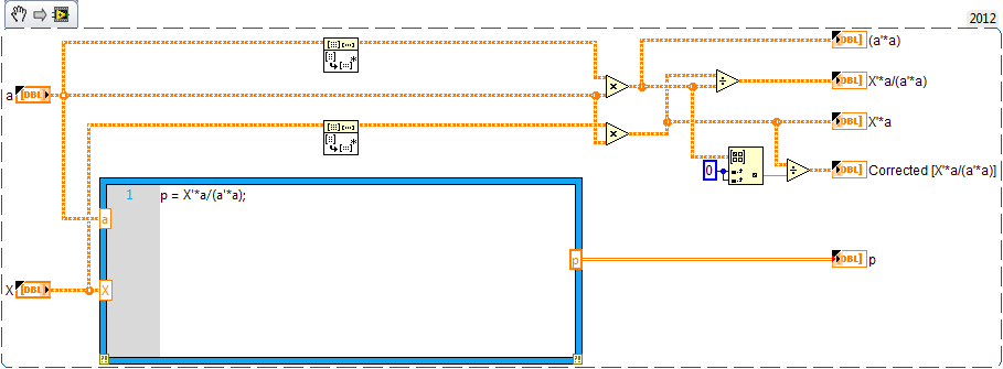
After a few days, I was finally able to get the results of the two screws is similar, but not the same thing. I was not able to find an explanation for it on the forums or elsewhere. The important thing I found is that LabVIEW breaks a little when you have a vector calculation as a ' * a, which should translate into a scalar value or a 1 x 1 matrix. When you use this value in another equation, such as the projection X'* a /(a'*a), LabVIEW works only on the first element of X'* a.
Here, it's in the GCode with the work around to correct one ' * a result:
It seems unusual that GCode treat a scalar result incorrectly. It was annoying, but I was able to go beyond that.
My next question is there is some apparent rounded differences between GCode and MathScript that I was not able to explain. This difference amounts to about 1% in the data I have to analyze. I've included the project where I worked to compare the two methods. In the NIPALS_Conversion_LV.vi the left side of the block diagram has a loop structure For which is where the model is generated using the NIPALS and the right side is the application of the model. The NIPALS_Converison.vi contains the original code of MathScript where I worked with.
Note that the difference between the two results is due to the calculation of you and matrices of B, which are related to each other because of the u. I probed the two vi extensively and everything is equal between them until the calculation of the elements in u. The equation in question is u = Y * ((Y'*t1) / |) (Y'* t1) |), even if it is expressed somewhat differently in the code.
Any help on this would be greatly appreciated.
Thank you
Drew
Drew,
I took a quick glance to your project and for me, it seems that you have correctly translated the MathScript in its equivalent in the graphical representation.
My first inclination on why you see this slight rounding error, is that the functions used in LabVIEW and MathScript can be different (from different DLLs). How these functions given floating point rounding may be different and spreading them error thanks to each iteration of the loop. I suspect that you notice that the error at this time in the program. If you compare every step of the script from the execution of LabVIEW and look out past 10 or if the bits of accuracy, I think you will see this error increase slightly after each step.
If you can find a specific function during which a significant difference between the script and LabVIEW execution occurs, I'd be happy to review the functions and the differences between the LabVIEW MathScript implementations of functions.
-Nick-
-
Combining results of the previous steps in digital test
I am relatively new to TestStand. Here's what I'm trying to do.
- Call VI A with numerical limits, make measurement, store the value in the local order.
- Call VI B without numerical limits, measure, store the value in the local order.
- Calculate: A - measure B. difference the result with numeric limits.
I need to create a very simple VI with two entrances, a subtraction function and an exit in a time limited digital LabVIEW to implement step 3, or is there a more recommended way to do it?
Thank you.
Stephen
Here's what I'd do:
Call VI as a step in the action. The measure in a local store
Call VI B as a step in the action. The measure in a local store
Use the None adapter to create a numerical limit step. Set the Data Source to Locals.AValue - Locals.BValue
-
Hey guys,.
I the DFD Toolbox and already built a few low pass FIR filter. I have a sampling rate of 50 kHz and I decimate it with a CIC filter with rate variable decimation. After the CIC filter, I need a high-grab for the low-pass filter FIR because I do want my DC signal. As I can change my rate of decimation, my FIR filter sampling rate changes also.
The problem is that the coefficients of the filter cannot be changed during execution as the Butterworth IIR-filter function, including labview has implemented in the mathematics of the fpga function palette section.
Are there examples how to build FIR filters where I can change the coefficients on the run?
Think you can build a low pass FIR with the DFD toolkit and simply change the table with the coef. for a control? I could change them on the track...
Greetz
Slev1n
Hi Slev1n,
just found it in the community, maybe this might help you already:
Polyphase Interpolation FIR Filter on FPGA with Diabaté and Coregen
https://decibel.NI.com/content/docs/doc-16650
Greetings
Michael
-
I am a beginner in VHDL, but... is there a bug here in LabVIEW?
In the configuration of a node of HDL to window, I selected the following settings:
X name:, Branch:, type: bool, length: -.
Name:, Branch:, type: [bool], length: 0.;
Name: Z, direction:, type: bool length: 0.;
LabVIEW then generates:
hdlnode of the entity is
generic)
13 kHz: Integer: = 40000000;
InSingleCycle: boolean: = false
);
port)
CLK: in std_logic_vector;
Reset: in std_logic_vector;
enable_in: in std_logic_vector;
enable_out: out std_logic_vector;
enable_clr: in std_logic_vector;
X: in std_logic_vector (downto 0 0);
Y: in std_logic_vector (1 downto 0);
Z: out std_logic_vector (downto 0 0)
);
end hdlnode;I'm confused why LabVIEW has implemented X and Z as vectors. This does not seem right, because:
X name:, Branch:, type: [bool], length: 1
and:
X name:, Branch:, type: bool, length -.
both produce exactly the same VHDL code.
Why must LabVIEW behave this way?
I expected, LabVIEW to generate something like:
X: in std_logic_vector;
Y: in std_logic_vector (1 downto 0);
Z: out std_logic_vector;Thank you
MarkA CAR is generated?
-
With a variable number of input ports on a Subvi
How can I have a Subvi with a variable number of input ports that can be changed in the other VI that uses the Subvi?
You can't actually do what you trying to do, how LabVIEW is implemented does not screw created by the user with arbitrary entries. And to be honest, there is probably a better way to do whatever it is you want to do.
If you really really want to do that, but... you can come kind of close.
1. create a new VI
2. change its connector to the one with the inputs and outputs pane more possible (terminals 8-6-6-8, 28)
3 create controls/indicators for any desired input/output of not scaling can connect the (i.e. the error in / error, son of reference, etc.)
4. hang them until the connector pane
5 count how many entries are left and create a control for each entry and their son all
6 drop your VI on the block diagram of the VI one another as a Subvi
7. Note that when you mouseover, it looks like a Pincushion
8. right click the VI and uncheck the "display as icon".
9. you can now "slide down" at the bottom of the VI
The terminals in the section "slide down" are as a package by name or node property that you can click on them to reallocate them to what it is not already selected. The default is to make all the entries in alphabetical order, then all the outputs in alphabetical order. If you rename the terminals that allows you to make appear in the order that you prefer is up to you.
As all terminals, for the best that you can do to detect if they are wired is to define a default value that should never be used. If she is floating points, you can use 'NaN' or 'Inf '. If this is a cluster that you did, add an item more boolean which is true in the default values for this entry VI.
Then just wire up all the identical terminals together in a table, filter the items which appear to be unwired and make all your treatment on the rest.
-
Synchronization of signals on my SBRIO problem
Hi all
I need some advice on how to complete my project.
I need to send a 32 bits of data to my unit test with the following parameters. CLK + FS + and +.
The clock runs at 4 MHZ. The FS + sends a bit length 33 of high for the treatment of the data signal, and in this context, I need to send my 32-bit data.
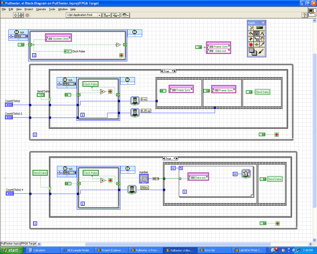
What I did is I created 3 loops as shown in my diagram.
1. the first loop is a loop timed to generate my clock pulses. I run at 8 MHZ with the low and high signals in loop rotation.
2. the second loop is for my frame sync signal using the rising edge of the clock over an external trigger (SEND DATA) to start the sequence. It has two red WAITING to the 0 graduation and 330 ticks (by tick is 25ns).
I have compiled up to this version of the code and run it with all the problems. I was able to generate the signal FS + 2ns after the clock rises and is to have cycles of clock exactly 33 in length.
3. the third loop which is I'll have trouble at this time is designed to loop data. I also used the pulse of the clock and the external data to start the sequence. I used one signal to WAITING to delay the start of the data by 1 clock cycle and use a loop for send data from 32-bit to 250ns (10 ticks) per line.
The problem is that I do not get the result I want. The departure of the bits is always erratic and not 1 clock cycle of delay that I hoped. Also the first bit is much too small for the 250ns.
Can someone tell me where I'm wrong? Is there another way to address the issue?
Your help will be greatly appreciated.
As a short response, I would recommend combining the three sets of loops in a single state machine. All three loops are intended to be based on the field of derivative 8 MHz clock.
As a longer answer and to explain the behavior you see... the time of the present code is assigned by the data through the areas of the clock. The details are in this help message LabVIEW FPGA: implementation of multiple clock domains with the overcoming of the areas of the clock (using a tunnel in the field to clock 8 MHz timed loop to the domain block diagram clock 40 MHz), LabVIEW is obliged to implement a hand shaking algorithm to maintain the integrity of the data. This shaky writing consumes FPGA (logic cells) tissue and takes 25ns several clock cycles to run, as well as creates unwanted delays. In addition, the third loop cannot guarantee that code data will trigger off the same synchronization signal as the second for loop because of the handshake that occurs for the data to pass through the loops of 8 MHz.
I would recommend that base you all of the communication out of a single loop timed in a configuration called a state machine. Essentially, timed with a looping structure business inside, where each picture of the structure of the case is a different State. Breast of a timed loop state machine, does not have the 'wait' function, so the delays must be implemented with a 'status quo' State which is repeated N number of times to match the time required. The following link leads to a state machine similar to the SPI communication that would be a good example for the implementation of this communication: Example of SPI LabVIEW FPGA.
The example above implemented the following communication scheme, which seems pretty close to what you implement:

This code is a little more complicated than what may be absolutely necessary to your application, but it is an excellent example of a scalable & flexible of the notion of core implementation (this code can easily be migrated to new hardware targets or add multiple replicated or modified communication to the same architecture protocols.)
See you soon,.
-
Add the delay between periods of a waveform
Hey all,.
I have used Labview to implement a generator of signals using the 'base FuncGen' VI, (WF-Gen.png) and I'm looking to make a change to the waveform. Currently I have my VI, set up to generate a square signal to a specified frequency and number of cycles. For example, a waveform of 1000 Hz for 1000 cycles would go for a second. My question is: how would I go put some points of zero V between each cycle? I've attached a picture to show what I mean (Signal.png).
Thank you.
GE
You need generate multiple signals and use Add a waveform.
-
Hi all
I have a problem with my typedefine. I bypass my implementation an example LabVIEW to implement the user interface for Teststand (Simple user interface). In the implementation, I was always able to add the recall in response to the events of Teststand in the past.
Recently when I try to add a new reminder to an another Teststand events, I get error saying that the master copy Typedef is not found or error. What I find odd are:
1. If the Typedef master copy was not found or error comes, why would the error affect the reminders already implemented for other events Teststand?
2. If the Typedef master copy was not found or error comes, why is it possible to run the program?
Here I have 2 screenshots. The first screenshot shows the reminder of existing, where there is no error of the master copy of Typedef not found or error. The second screenshot shows the error when adding a new reminder.
The main copy of Typedef, call TestStand UI Data.ctl is also shown in 1 screen capture, and it is located in the TestExec.llb, as shown in the third screenshot.
I'm not sure how to start debugging this problem, that is why I hope that LabVIEW experts out there can give me some advice.
I am using 32-bit LabVIEW 2014 and 2014 Teststand 32 bits. Running on the Windows 7 system.
Thank you.
Yours sincerely
chati
Hello Bob_Schor,
I don't think that it is a problem of Teststand, rather a problem of LabVIEW. But I could be wrong. I'll close the display here. Open a new message in forum Teststand.
Thank you.
Yours sincerely,
chati
-
Active control of vibration of the flexible mono-faisceau
Hi, im working on the active control of vibration of the unique flexible built-in beam, and I need to design that helps me control the beam active & passive.
two experiences of control a robot with unique flexible bond. The link is operated in bending by two piezoelectric glued to the surface, and the local curvature is measured by piezoelectric sensors, forming a pair of sensors/actuators colocated. In both experiments, the articulation describes the same polynomial trajectory that excites the Eigen modes of vibration of the binding. In the first experiment anti-vibration with piezoelectric actuators are off, and we can observe a very long time to maneuver as link oscillations themselves naturally. In the second experiment anti-vibration are lit, and a significant reduction in the time settling is reached
material
1 - nor cdaq-9178
2 - PS piezo
3 - piezo amplifier
4 inputs daq 9215
5-output daq 9263
performs one of the two substances vi my requirement
Cabo,
So, it looks like part of what you are trying to do is the generation control system a PID in LabVIEW. Fortunately, LabVIEW includes a number of useful resources for the PID:
Here is one of our books (with the tutorial files) whites, discussing implementations in LabVIEW PID: http://www.ni.com/white-paper/6440/en/
Here is another tutorial on implementing PID using the PID.vi: http://www.ni.com/pdf/labview/us/implement-a-pid-control-system.pdf
Here is the help documentation for PID.vi himself: http://zone.ni.com/reference/en-XX/help/371361L-01/lvpid/pid_vi/
Finally, example finder LabVIEW has a large number of projects example PID you can experiment with. Just go to help > find examples, then find "PID" and select any project matches your planned the best implementation.
-
implementation of a function of time transfer real Labview program
Hello
I want to spend my control signal U through the 146 function /(S+276) for U_filtered
How do I?
I tried a low-pass filter, but I have the same results in comparison with Matlab.
I mean I want to have:
U_filtered = 146 /(S+276) * U.
I have attached a picture for the signal U (yellow) and U_filtered (pink) in Matlab.
I want to use in a real-time application
Thank you
How you implement the function of transfer in labview?
I think this should be a separate implementation and maybe you already do. So forgive me if this is something you already know.
Please see http://en.wikipedia.org/wiki/Low-pass_filter#Discrete-time_realization for an excellent time discreet introduction, low-pass filters.
Essentially, you have to implement a discrete equation to achieve this. Something like:
y(k+1) = 0.53 * alpha * x (k) + (1-alpha) * y (k)
where alpha is related to the low-pass frequency and the frequency of sampling by alpha = flp /(fs+flp), flp is the low frequency of success and fs is the sampling frequency.
In your case, flp = 276 and fs, it's whatever you choose to implement: it is the speed at which your loop runs on the RT or the FPGA or whatever. If speed is not a problem, I recommend 5000 rad/s or above as a starting point.
The factor of 0.53 above is just the gain of the filter described you 146/276.
Maybe you are looking for
-
iOS update broke my home button
I just updated my iPhone 6 with the new update and now my home button only works for the double tap is not going to the home screen
-
Purchase 2013 (initially) Macbook pro 15 inch
Hello world! Then my trusty old 2011 (early) macbook pro died last year. After making it through high school and college, he was finally ready to retire. My trackpad was broken, the screen has been damaged, and I was running out of ram which was caus
-
How to get the toolbar in photo open in the view tab. It does not allow me to highlight and allow toolbar display.
-
Satellite Pro A10 - installing the audio driver on Win XP
I have a computer Satellite Pro A10 and the audio driver is not respected my model above.Please send me the audio driver and I have installed window XPThank you
-
How can I run a system recovery?
Hello Anyone know how to run a system recovery? My machine is: Toshiba Satellite L300D. I tried ' the power of restraint button for 10 seconds and then press on and hold zero keys "(Http://www.toshiba.com.au-online home > support > FAQ > how can I ge