Loop of FIFO
I use a RT FIFO to pass data of three analogue channels in a timed loop, sampling to 32 Hz, for a secondary loop to write the disk, see attached jpg. The vi seems works correctly except that the first line of data in each data file is repeated, see attached txt file.
Comments or suggestions about the possible cause of this behavior would be appreciated.
Best regards
amendments
Thank you both for your responses.
It seems that using a FIFO as I do isn't the best method of data transmission of a loop of sampling to the loop of Scripture, even if I got the idea for a tutorial for NOR, see http://zone.ni.com/devzone/cda/tut/p/id/11198. The problem is the synchronization between the two loops.
Another approach is to use a queue, which has now been implemented and seems to give data in the required format.
Best regards
amendments
Tags: NI Software
Similar Questions
-
Hello
I use 2 loops on a CompactRIO 9074. One is for the deterministic i/o, synchronized with the scanning engine and the other for the e/s network with a client PC. I'm waiting for data in the network using shared variables published network loop, and when I get my data, I want to transfer (data are 2 tables, one is an array of double, the other is an array of boolean) to the deterministic loop using the RT FIFO (or any other type of method non-blocking also).
The deterministic loop works at 10 Hz and bed 2 RT FIFO containing the respective tables. It's probably nit-picking, but I want to assure you that in a deterministic loop iteration, the tables in the RT of the FIFO have both been updated. I'm not one of them have been updated while the other is being be written in ring network IO, for example:
-Deterministic loop-
FIFO of RT read [double table] (new data)-> RT FIFO read [table of boolean] (old data)->...
If I could group data to help somehow something RT FIFO-like, that could happen not that I would write to a variable only.
Any suggestions?
Best regards
You can turn the table of Boolean values in integer values (Boolean matrix to U8) and then transfer them in the FIFO even as the double. If you nailed this value on the end of the double table before placing it in the FIFO, you just would read a table on your another loop.
-
Read and write in two separate FIFOs DMA on RT host
Hello
I have two parallel loops running on a host of RT on a CRio9022. There are two DMA FIFO: one of the FIFO is written for in the upper loop, another FIFO is read from the bottom loop. I've attached a screenshot of my code.
The problem I encounter is that I seem to be only able to run one of these loops - for example if I disable the first loop, I can see data through the second loop. Trying to run them in parallel because I think I've coded it means only one of the tracks-it loops is always the top loop in the code that I have attached the screenshot. Each of the FPGA VIs that run only use a FIFO so I think they should be able to run independently... I was wondering if anyone could shed some light on this?
Thank you
Hello.
You can only have a single call to the FPGA in HOST mode, the algorithm that you post, that is make two calls to the VI 'Reference of VI FPGA open', this is not allowed, this is why the program works only with one of these cycles.
Kind regards.
-
Rare use FPGA build without sample FPGA build
Hello
I hope I can formulate my question in the right way. I want to test a routine of FPGA and do not always want to compilate hole streaming project (e.g., construction with bus register etc.). Is it possible to only build a simple FPGA bitfile (simple while loop, some fifos, my code) and test on the device of the USRP RIO or what I need to use the basic FPGA in Streaming Xcvr as base build? This would be really shorten the compilation time to test the new code.
I hope that my question is understandable.
Concerning
Etuel
Yes, you can start from a blank VI FPGA and develop FPGA code similar to other LabVIEW FPGA targets. There are a few things to point out:
- You will not be able to use the host of the project example screws if you do this. If you don't have the FPGA of the sample project code, the host screws will not good FPGA logic to connect with.
- I recommend not to put any code in the domain of Data Clock. Data clock requires the USRP RIO IDLs configure this field of clock. To do this properly, you need the '' necessary '' of the FPGA block diagram section. It is easier just to avoid all this. To use the clocks faster than the clock of 40 MHz, derive a new clock, the clock of 40 MHz.
Good luck!
-
LOCATION:
-I am developing a software plugin based on plug-ins based on LabVIEW classes that are instantiated in running. Plugin real classes come from the plug in generic classes that define interfaces to the VI instantiation and can provide basic functionality. This means that many of the methods of the class are dynamic distribution and even methods of child classes can call the parent method.
-Plugins top level (the ones directly accessible by the main VI) each have a run method that animates a plug-in specific state transitions.
-Transitions of the plug-in data acquisition (DAQ class) class calls a method of the DAQ class that reads data from an FPGA card OR and transmits to another component via a queue.
PROBLEM:
-Higher sampling rate, a FPGA-to-host FIFO overflow occurs after some time. When I "weigh" the system just by moving a window of Firefox browser on the screen, the overflow is triggered immediately. I did not have this kind of problem in older software, where I was also reading a FIFO of FPGA, but made no use of LabVIEW classes or diagrams.
SOLUTIONS I'VE TRIED (WITHOUT SUCCESS):
-J' put the transitions in a timed (instead of a simple while loop) loop that I assigned specifically to an own kernel (I have a quad-core processor), while I left all the other loops of my app (there many of them) in any simple loops. FIFO overflow still occurs, however.
QUESTION:
-Does anyone have a tip how I could fix this problem? What could be the cause: dynamic distribution methods, the acquisition of data of state transitions or just the fact that I have a large number of loops? However, I cannot change the fact that I have dynamic distribution methods because it is the essence of my architecture...
Tips are greatly appreciated!
I've now changed the execution priority of all the screws involved in reading of the FPGA FIFO '(highest) priority critical time '. This seems to be improving the situation much: so far I have not a FIFO overflow, even when I move around the windows on the screen. I hope it stays like that...
-
With the NI 9205 module Max sampling rate - problems
Dear friends,
I develop a project of lv, which makes and control system of engine dyno. The material is CRio-9022 with other cards and also 9205 for AI. There is an encoder for angle attached to the motor shaft with 3600 chatted by Tower as well as an index to indicate the end of a revolution. the output of the encoder is measured by card 9411. The speed of the motor is 1500 rpm. I measure pressure data and couple when I receive a 'tick' of the wheel. This means my sampling rate for pressure and torque each is 90KO/s.
but I was not successful to lead it. The program is great and I can show them, but I believe that there is a problem in the choice of material for the task. With the data of pressure and torque of the 9205, I also measure other channels for the controller output mass flow and temperatures. So in all I use 8 channels of the 32 available. But only the pressure and torque are acquired at the wheel-driven sampling rate. the rest are acquired about 5 times per second.
Since the 9025 is a multiplexing ADC, 250K sampling frequency is divided by the number of channels accessed = 250 K/8 = 31 K samples/channel. With this in mind, I decided to acquire data of pressure and torque with each beat 3rd rotary encoder, essentially on 30K samples/s sampling. However, I see a large amount of noise.
So I decide to average more than 1 second cycles (so the engine runs at about 25 cycles/sec, I averaged over this issue). The resulting pressure and torque graphics do not match with those measured by an oscilloscope in terms of amplitude but the frequency and shape is correct.
I noticed an interesting feature in the charts. When I pass interpolation between the points, I see several curves made by points instead of a continuous locus of points. Accordingly, I find that the acquisition is slower than necessary, and so there are less number of points sampled as required. These points are not synchronized 25 cycles I have on average and therefore the separate "curves". It is because of the possibility that some points receive a higher number of 'contributions' several times (when you add), the neighbouring points.
so I conculde that the 9205 is not fast enough to do the job. also noise, perhaps due to crosstalk or gosting when the mux changes channels. the impdences output pressure and the couple are of the order of 10 K ohms.
the Labview code outline: well, there is a vi FPGA, which takes the rotary encoder ticks and sends a signal to the case of each 3rd tick. The signal contains a 16-bit integer, indicating the number of ticks. This signal is sent to a 1 element FIFO. This fifo is read in a parallel while loop, where it remains awaiting a new element. The while loop bed fifo, where data are available, takes a measure of pressure channel. A node memory of the method is called to provide data according to contained in the index number equal to the number of ticks to signal fifo. Then he adds the current pressure reading to the reading of the memory and stores the sum in the same memory location. Thus, an array of elements of 1200 is formed, where each elemnt is a sum of the values taken of more than 25 cycles. This memory is transferd to a dma fifo and reading side host. is done similarly to involved couple. host-side the fifo is read and divided by 25 to get the average. This average is displayed on a waveform graph.
Please check the attached file to get an idea of the problem. Sorry for the long post.
Please suggest if you understand the problem and suggesstions or solutions.
-
I have to define several of the FIFO to synchronize a master loop at three other parallel loops?
If I have a single loop to generate a waveform and I mean, three other parallel loops to extract the values from this first loop via a FIFO defined by VI, must I place three separate FIFO components 'Write' (essentially by defining three different FIFOs) on the first lap which correspond to the three elements of FIFO 'Read' in each of the three loops accessing data of the first loop?
The problem with the help of a simple FIFO, is that when a value is read, the value has disappeared. The other loops will not see this element. And since it looks you speak too well of FPGA, you would have to worry about arbitration as well.
You need a different FIFO for each loop that you send.
-
Variable single process shared w/o (without) FIFO between deterministic loop.
Hello
Why we cannot use variable shared unique process without FIFO to communicate between deterministic loop? In other words, why it is always recommended to use FIFO for communications between the deterministic loops?
Thank you
Ajay.
It is called sharing resources. When you use a variable shared unique process, only one thread accesses it at a time. So what is happening is a tent to read, but B is busy writing on it. So wait, adding a jig.
With the RT FIFO active, you don't have this problem. One can read from the FIFO as B adds another element.
-
sbRIO9637 the corruption of data to loop speeds
Hello, I send a waveform AO0 and extracted AO1 of loop using a FIFO, is attached. If the timer loop is 1 msec then the output is clean. However when I take the timer loop up to 50 usec (20 kHz) can I get occasional glitches in the output, a record of the scope of such an event is attached. If I take the loop up to 20 usec timer, then the total duration of the production is not much shorter, but the waveform is severely damaged. I would like to understand how corruption occurs and how to get reliable results with a 50 kHz update rate. I'm guessing that the fracture of fixed point might use too much CPU, but I do not see how to put a value I16 in the 16 bit DAC, it expects a voltage of + /-10.
Thank you
JEB
Hi John,.
Good job governs me execution of writing - the big problem was adding a loop FOR and placing the FIFO_Write inside the loop. This means that I said to do the tail 3, a thousand times in a row. The idea used FOR autoindexing change table 2D in a 1 d accepted by the FIFO entry. But as I learned periodically in LabVIEW, never do something with a loop FOR if there is a VI somewhere who will do the same thing in one bite! In this case Array reshape transforms the data directly into a table 1 d containing all points (see extract), and I ask all points at a time.
With this change it on at 320 analog net Ksamples/s on. It is close to the maximum side, so the results are now considered to be very good!
(problem solved, but I do not see the button for this)
thanx
JEB
-
Hello world
I have a custom device which initializes without problems, but I can't understand how to use at run time. I used the Inline HW model to create the device. The definition of system deploys on the FPGA target, but I can't read or write to the FIFO. For the purposes of learning, I write just three constants true that activate the three LEDs chassis. When I deploy to the target, the lights are not upward.
I created a VI using similar code that doesn't use VeriStand. The difference is that I use a while loop to read and write items FIFO in functional VI, while the generated custom device a model pilot VI that uses a case structure and an enum to determine its mode. I have to do something wrong... does anyone have pointers?
Thank you
After scratching my head for hours, I finally realized that I never wired a real constant to the control that actually starts my FPGA VI... Oops! Thanks for your time.
-
pairs of IQ should be concatenated before fifo had?
I'm trying to understand the 'Xcvr (FPGA) .vi Streaming' vi which is located in the BasicTX_BasicRX project. This is the example that does everything on the fpga and works with the 310 x (I hope). If I understand each 16-bit pair IQ is concatenated in a 32-bit integer before being sent to a FIFO. Is there a reason I can't use 2 16-bit FIFO? Is there a risk that they might fall out of sync relative to each other if they are in the same timed loop? It would certainly be easier to read.
apchar,
I'm not familiar with the BasicTX_BasicRX project, but if it is based on the USRP Simple streaming project, then Yes, you can divide your IQ samples (and channels) into FIFOs separated without any problems of consistency. You need to change your host code to fetch multiple FIFOs, but you will not have to worry of their "falling out of sync with eachother.
-
Good practices of FIFO: updated old cluster or create new
Hello world
My question is more on "good practices" that really solve a problem.
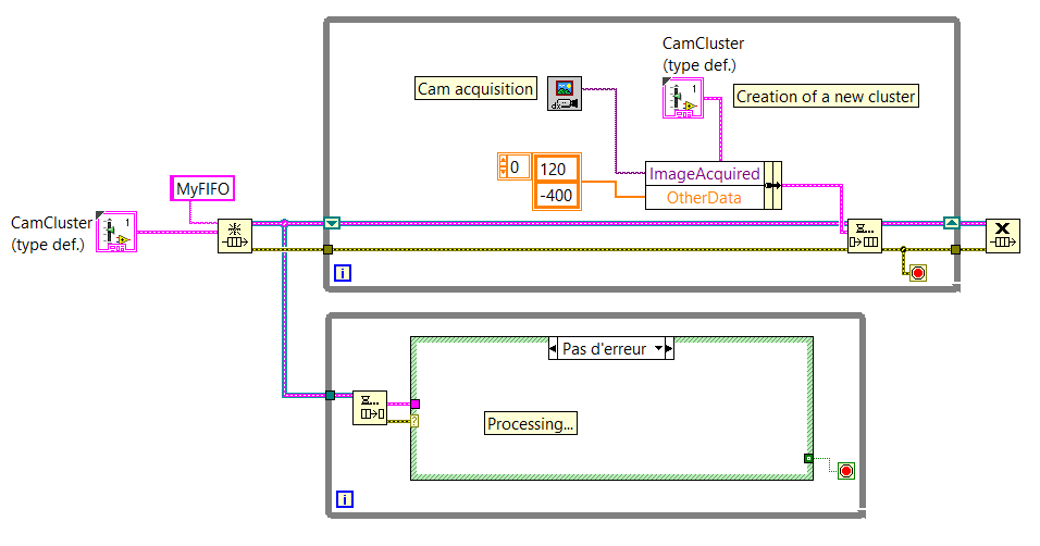
I use FIFO to send images and other data from a producer to a consumer.
I created a cluster which includes all the data that must be sent through the FIFO.
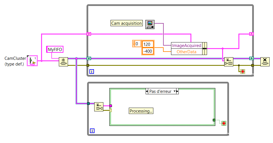
My question is: can I create a new cluster to each loop of the producer and put this cluster in the FIFO or should I set a shift and then register and update the data of this fallen registry change by sending in the FIFO?
Below you will find two screenshots that sums up the idea (NB: these aren't the real VI.) We come here to show the general idea).
If there is a difference (in the way that the computer uses memory for example, or something else...) between these two methods of programming, you will give me some details so that I can understand why to use one over the other, please?
Thank you very much.
Best regards.
Luke
I think that there is very little difference in terms of performance (perhaps the registry approach change is slower than sliiightly - but probably not noticeable in most cases).
The main reason you want to use the shift register approach is that if you update only certain values before sending the data in the queue, those that would be lost if you created a new cluster each time. For example, if 'Directories' was constant, you could just power/updating that once the value to the registry to shift and just update the part "ImageAcquired" of the cluster before you send it in the queue. This also means that if you update your cluster to have more elements (using a type-def, of course), you can be less worried about having to update the individual elements.
I think it is less a problem of performance (both are valid and effective) and more a matter of maintainability and flexibility.
-
Target to host DMA FIFO - actual number of items
Hello
I have a target of FIFO of DMA host using memory block. Under FIFO properties, "the actual number of elements" is indicated as part of 1023.
But when I wire a remaining indicator to the 'elements' of FIFO in the host of VI, said 16384 elements. And I read a lot of part of the FIFO.
Why is the actual number of items that much more?
The data type is 32. And I have a high-7965R FPGA.
See you soon.
There are two different buffers for the FIFO: one on the host, the other on the FPGA. Data is copied from one to the other. It may be more space allocated on the host, because there are more memory available here and the loop of the host, probably runs more slowly than the FPGA. You can set the host using a node to invoke FPGA FIFO set the buffer size value.
-
Then as the loop timer Timing vannes_ouvertes. Elements
I would like this while loop to iterate through every second. But it seems that he doesen't recognize the loop timer. What's wrong?
Just found the article to help talking about it: Debugging of FPGA screws using Mode Simulation (FPGA Module)
At the bottom, it says:
Understanding simulated time on the host computer
If you use some FPGA resources and you run the FPGA VI in simulated using I/O simulation mode, the resource uses simulated time rather than real time. Simulated time could be faster than real time according to the number of events that occur during the simulation. For example, if you add a waiting VI (simulated time) for the schema and set the timeout to 1000 ms, LabVIEW does not attempt to delay a second of real time. Instead, LabVIEW delays as long as necessary before performing the next action scheduled in the simulation.
The following resources are using the simulated time on the host:
- Then the loops
- Single-Cycle timed loops
- VI of waiting (simulated time)
- Loop timer Express VI
- Number of cycles Express VI
- FIFO, except DMA FIFO
- Wait on Occurrence with Timeout based on ticks
- Interrupt the VI, during her wait until this that clear is TRUE
-
Hello world
I'm new to the part during a real-time/embedded Labview and I'm just starting to play with the RIO evaluation kit.
I stumbled upon a phenomenon that I do not understand... So maybe it's a stupid thing, so I apologize in advance.
I have create a FIFO on the FPGA target (configured to Traget - to - Host DMA) and put the UINT16 5Million of a FPGA loop values, as soon as possible. Now, amazingly, I can read either with a VI on the chassis in real time, but also with an identical VI located on the PC host, even with similar performance.
In fact, I don't understand where the data are buffered and how the PC can access. I thoght the FIFO DMA memory needs to be on the RT target, right? So, how the data comes to the PC without a RT - VI? I guess that this method of data transfer (FPGA-to-PC) is not a use of FIFO, right?
In addition, when I check the property of "Possible elements" of FIFO in the PC - VI or RT - VI, I get numbers approximately 8000 to 10,000, while FIFO is configured with 1023 elements only.
How is that possible?
(Btw.: I realize that I'm losing a lot of data and the FIFO is small.) Yet, I want to first understand the points above).
The project is included in the ZIP.
Best regards and thanks for your efforts,
Joe
Hey Joe,
NEITHER offers a service called NI RIO Server. This service is installed with LabVIEW RealTime on your target in real time and allows you to connect to the FPGA of the cRIO/sbRIO from a computer.
I can't find a lot of information available on the internet, this page only:
How to make the devices to access RIO on a computer connected to the network? -National Instruments
http://digital.NI.com/public.nsf/allkb/43F81436B97AEE28862573D40069F440He is the Francis, why you are able to run the same program in real-time on the RIO and the development computer. It is also the reason why you must enter the IP address of the target in real time on the program running on the development PC. If you run the VI on the RealTime Taraget itself, it is not necessary to enter the IP address.
Some information on the size of the FIFO:
The FIFO is not only a buffer. A buffer of contains two FIFO.
A buffer is located in the FPGA itself. It is unbelievable small (1023 elements by default), but this buffer is super fast. The size of this buffer is configured as part of the LabVIEW project. You can increase the number of elements in the buffer zone, but you will never be able to achieve an elements > 20K buffer size due to the constrained resource of the FPGA.
The second buffer is located on the site in real time of the RIO. This buffer can be bigger than the buffer on the FPGA, usually 10 x or more. You can configure the size of the buffer of site in real time by your LabVIEW Code on the part in real time.
Best regards, Stephan

Maybe you are looking for
-
How to delete a Photo Album that came from my Mac to my iPhone. I want to remove it from the phone.
How to delete a Photo Album that came from my Mac to my iPhone. I want to remove it from the phone. I do not use the cloud. Just sync with USB.
-
I have a system dual boot win - xp & win - 7. I reintall win - xp that disable my dual boot and I have win - xp. I'm trying to repair it with win 7 dvd but it only recover win - 7. can I pick up my dual boot? Help, please
-
A phone call to Microsoft technical support trying to supposedly help to fix a PC infection
Hello FYI, I received a phone call in Somerville tonight of a number blocked a man with bad English. Maybe Indian, who claims to be from Microsoft Technical support telling me that he needed me to turn on my computer to correct an infection. He gave
-
What other can I replace my DDR400 (CL3) with thnx
What other can I replace my ram DDR400 (CL3) to THNX Board
-
Why Vista will not connect to the internet wherever I'm connected with my XP machine?
Why my computer won't get online wherever I like Xp only Why Vista will not connect to the internet wherever I am? I thought what to see that there is a link to a site to repair this, but when I found the site the link had disappeared. Thank you