Measure of angle polygons
Hello
I would like to create tiling Cairo-Pentagon.
Pentagonal paving of Cairo - Wikipedia, the free encyclopedia
Last year I had asked on triangle custom angle, gladly someone helped me but now I am facing a problem to create different polygons cranked up in illustrator. Of course it can be done manually, but I would like to create a lot of tilings as a reason for Cairo. For example, he has 5 faces and their angles are 120, 90,90,120,120.
A Script would be great that allows the filling of a box with these figures and creates these polygons.
Also last year CarlosCanto had helped me and its polygonal scenario was: (this script creates polygons with custom length and side numbers. What I need at this point is before custom angles. If it's hard to create number of sides in addition option, it would still be useful to have the script Pentagon with custom angles. Thank you for your help.
#target Illustrator
// script.name = polygonBySide.jsx;
// script.description = creates a polygone based on side length;
// script.required = an open document;
// script.parent = CarlosCanto; // 11/21/13;
// script.elegant = false;
// Shared via Creativetuts.com – Author : Carlos Canto
if (app.documents.length>0) polygonBySide ();
else alert (“no document to draw the polygon”);
function polygonBySide() {
var title = “Create Polygon by Side”;
var sideLen = Number(prompt (“Enter Side Length in Points”, 20, title));
var numberOfSides = Number(prompt (“Enter number of sides”, 5, title));
//var s = 2*r*Math.sin(Math.PI/n); // side length = 2*radius*sin(180 deg/number of sides)
var radius = sideLen/(2*Math.sin(Math.PI/numberOfSides));
var idoc = app.activeDocument;
var ctr = idoc.activeView.centerPoint;
dw = idoc.width;
dh = idoc.height;
wc= dw /2;
hc = dh *-0.5;
var ipoly = idoc.pathItems.polygon (ctr[0], ctr[1], radius, numberOfSides);
ipoly.position = Array(wc-(ipoly.width/2),hc+(ipoly.height/2));
}
something like this will draw the shape you want.
but it would be quite a task to allow the user to enter all angles, etc...
var L = 100;
var Sx = 100, Sy = -100, h = L/2, g = Math.sqrt(3)*h;
var points = {
    a : [Sx,Sy],
    b : [Sx+g,Sy+h],
    c : [Sx+g+g,Sy],
    d : [Sx+g+g-h,Sy-g],
    e : [Sx+h,Sy-g]
};

var doc = app.activeDocument;
var shape = doc.pathItems.add();
shape.setEntirePath(Array(points.a,points.b,points.c,points.d,points.e));
shape.closed = true;
shape.filled = false;
shape.stroked = true;
shape.strokeWidth = 1;
Here's a Visual of your form.
It can be broken down to still 4 triangles and a rectangle.
All triangles are 30-60-90, so the calculation is fairly simple.
Edit: Sorry, in the script I use 'h' and 'g' for the triangle not 'a' and 'b' as the diagram below.
In addition, point.a is the left most point and it works in a clockwise direction around the shape.

Tags: Illustrator
Similar Questions
-
How to measure an angle specified in Illustrator? Help!
Hello
I have a big problem that seems very easy, but I can't find a solution on the internet. The problem is. I have a rectangle, all angles are 90 degrees, I know. But how can I make Illustrator to measure this? Using the window - info I really don't know how to do it? It's in another place? It is a fundamental feature, that according to me, and I can't believe that it is not possible. Please let me know or I'll go crazy before Easter.
If you happen to know how to do, I also have another question. How can I measure something in Illustrator so that it leaves a measure on the screen, like in Corel, if I measure something, a distance, for example, he shows it to the screen and it remains on paper, so if I print it, I. In Illustrator, I just can see it in the information window, but how can I do to stay and be printed?
Thank you.
Tomasz
The beast that's...
Measurement of the Illustrator tool is useless garbage. The online tool is a measurement tool better.
1. make sure that Snap Points or SmartGuides is on.
2 line tool: drag to draw a "line" (it's actually a road) connecting two points of bwtween you want to measure the angle.
3. delete.
4. double-click on the tool online. The dialog box will tell you the angle and length of the path you draw.
Illustrator never provided a set of tools of appropriate dimensions, such that it is taken for granted in programs such as the draw and canvas (just as he has never provided such basics as objects of geometric primitives with changeable parameters, such as rounded rectangles that you can change the rays or polygons on which you can change the number of sides (, or arches on which you can change the angular scanning...)
My JET_DimensionLines.jsx script is a heavy workaround for only the very simple kind of linear dimensions. It will help you label the angles.
I highly recommend keeping your copy of the day draw and continue to use it. There is no law that you cannot use drawing software. And Illustrator is a program very antequated which is very inadequate in too great numbers of very basic functions.
JET
-
Hello illustrators.
I would like to know how to measure the angle of this form/RADIUS, I think it might be
is there a corner angle, as I can see using a tool.
Thank you.

Draw a horizontal line from the top left. Keep it selected.
With the rotation tool click on the far left of your line and then drag until the smart guides will tell you that your line coincides with the oblique top edge of your trapeze. Smart Guides will tell 'path' or 'anchor '.
Now, double-click the icon of the tool rotation, and you will see the degree of rotation in trhe dialog box.
Unless you want to rotate again, click Cancel.
-
The measure of Angle isnig DAQ 6009 phase
Hello
I am in a position two analog signals with the USB DAQ 6009, I wonder if someone has a tip,
or know any tool of angle measurement of phase of these signals using LabVIEW.Thank you
Ednaldo Cruz
Take a look at the iunformation of your unique extract VI found in treatment of signal-measures
Capture > 10 periods
Keep in mind that you have a multiplexed input, so you measure a certain delay in all cases.
(apply the same signal on both channels, for each sampling rate used, measure the phase, calculate the "group delay" for the correction)
-
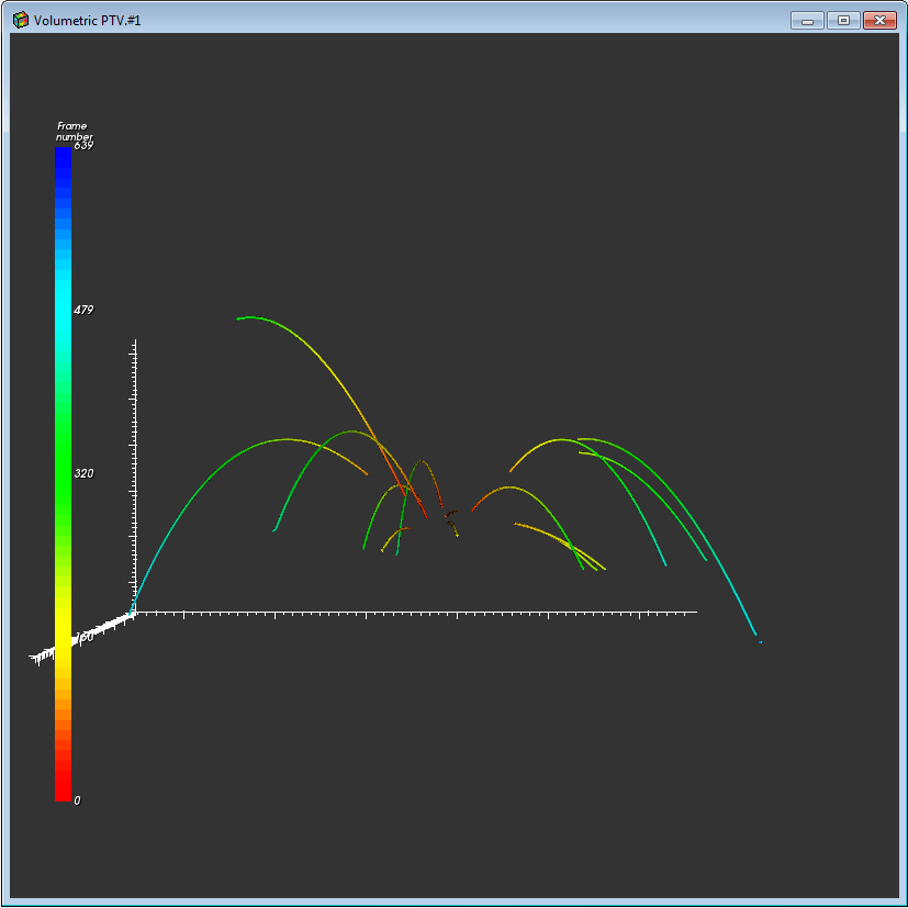
Measure of angle from XYZ positions
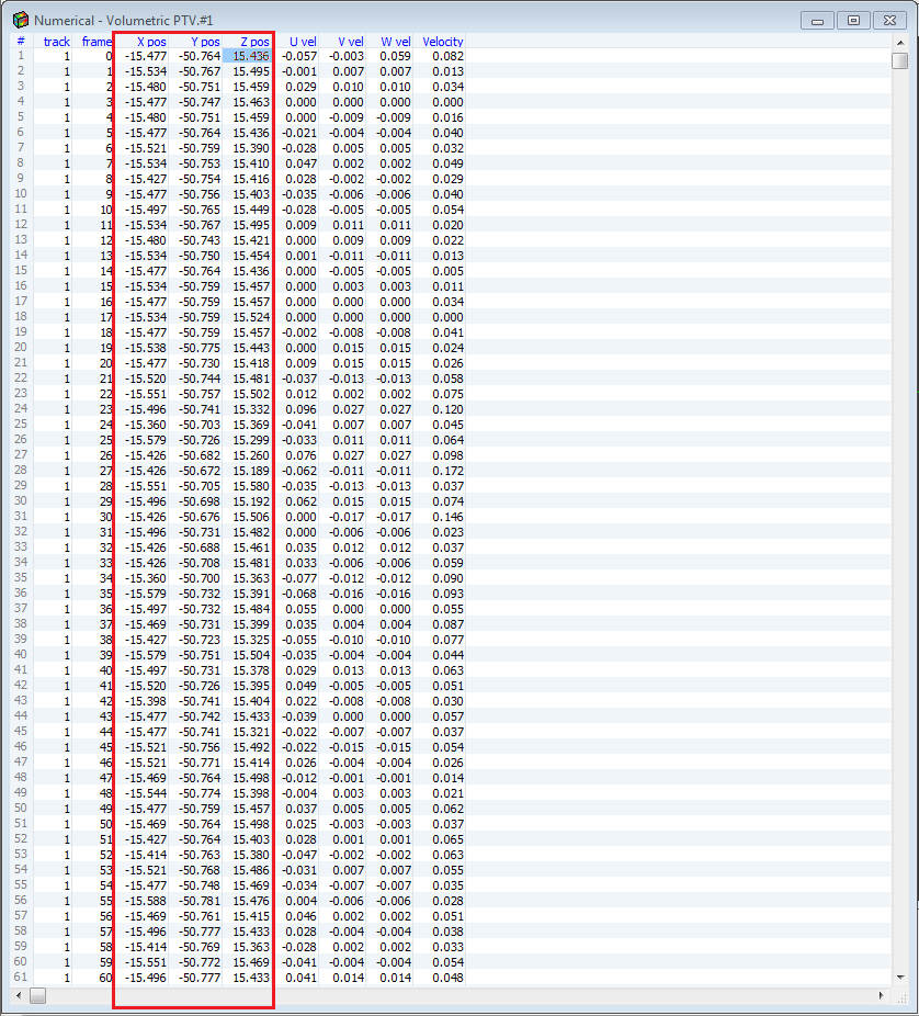
I made a 3D particle tracking image. It is (in this example) 17 tracks including the point of start in 0,0,0 (XYZ). Some of them didn't start the part of track (tracking problem), but it is not serious.
I also have a digital picture with any XYZ positions for each particle in the following frames. Now my question: is it possible in LabView to measure the initial angle (start) for each track of the first 10 frames (1-10)? On the photo above shows could be an angle for part of the beaches marked in red. There are only the initial angle, another part of the beaches is not bad actually.
Greetings to you.OK, it is not too difficult. You have a point P (I will choose 20, 34.5, 20), origin O (10, 10, 10) and you want to know the angle between the line of origin upside (call this OP line) and the line that is the projection of OP on the plan through the origin XZ.
Let's start with the passage of the origin 0, 0, 0. We do this simply by subtracting O p, which gives us a new point P' = 10, 24.5, 10. The point on the XZ plane is simply P' with its component is returned to zero, 10, 0, 10. Since our origin is (now) to (0, 0, 0), points P' and the projection of P' also represent vectors from the origin (that is, they are 'lines').
We now use the fact that the scalar product of two vectors is simply the product of the length of the two vectors times the cosine of the angle between them. I assume you know how to calculate a scalar product (if not, there is a function "Dot product" practical mathematics, algebra linear subpallet) and the length of a vector (vector Norm, even under Palette). The division, take the arc-cosine, and you should get (approximately) pi/3 (I took 24.5 = 10 * sqrt (6) I figured it would give me this angle).
If you write this as a Subvi with particle XYZ and XYZ origin (2-3 items 1-D tables) and Theta as output, you can put this inside a loop For that subscribe to all of the 2-D array of particles and the only original value and it will return an array of Angles.
I hope it's clear.
Bob Schor
-
Hello friends
I need to measure the angle of rotation of the shaft with a precision of 1 degree... is there any simple device can I connect with usb 6008 custom angle...
Thank you
180 degrees is very different from continuous rotation. Just wire a potentiometer to one of the analog inputs and try to calibrate it.
You don't need the LM317. It will not help you with what you have described so far.
Lynn
-
measurement of continuous degrees
Hello
I have an arrow that revolves around constant point. I measure the angle of rotation of this arrow. When the arrow cross 90 degrees instead of 91 degrees East - 89, instead of 180 is 0. How to make a continuous measurement of 0 to 360 degrees?
THX
Here is a quick sketch. Most likely, you will have to tweak it a bit depending on how you set the angle.
(A lot of your code much easier...)
-
Problems VeriStand 2011 RT and SCXI-1540
Good afternoon
As in the topic, we have problems with our card module SCXI-1540 that we use to acquire a mixed selection of RVDT and resolvers.
Specifically, we have our facility on Veristand 2011 on a target of RT who has a device custom control map SCXI chassis PXI-1050 and the NI PXI-6221 card, everything is fine but every now and then the map 1540 suddenly start showing a rolling measure of angle for resolution programs.
By checking with an oscilloscope, resolvers entries are good, but we notice that when the event occurs, the excitement somehow pass set 5 kHz to 10 kHz and even by the cancellation of the deployment and redeploy the project and verify that the property node DAQmx channel used to set the frequency of excitation is the correct setting of 5 kHz and does not return an error There is no way to get the channel back to 5 kHz, and it remains stuck at 10 kHz. The only way to be able to control the frequency of excitation again is through a power cycle of the RT/chassis.
We checked also by adding debug code in the custom feature event is the channel of sin or cos channel starts showing a rolling measure voltage so our measure of angle begins to roll too.
So far, this behaviour seems to have manifested only with programs of resolution that we mainly tested those and synchronize us excitement between a sin / cos pair.
Please notify
I just noticed that I never gave a solution for this.
The problem was current flyback to another causing system glitches of EMI on the lines of resolvers somehow mess with map of 1540, which essentially stopped decoding of the resoulvers of entry correctly, I added a Reset custom device close the file and that fixed the not being able to get out of the excitement of 10 Khz on the redeployment. However the final fix was adding flyback diodes to the tokill power system high seeds. So beware of your configuration as module SCXI-1540 cards seems to be sensitive to such events.
-
Sample USB - 6343 Counter clock
I use a USB-6343 CTR0 to measure the angular position. I expect to ~ 1 million encoder pulses (or account) per second. What USB-6343 clock signal would be preferable to use the counter sample clock?
Dar Hi,.
At what resolution do you need measure the angle?
One of my colleagues has compared the maximum sampling frequency on the counters of series X USB to be approximately 8 MHz for a single channel, continuous operation for 10 minutes. However, if the signal that you intend only generates pulses at 1 MHz, 8 MHz rate seems unnecessary because you will receive the same reading several times.
Concerning the two methods you mentioned, either would not be possible:
(1) you could count the external signal and sample at regular intervals. For example, if 10 kHz sampling you'd expect to see ~ 100 strokes per sample if clock signal is 1 MHz.
(2) you can also use the meter to count a time base internally (for example 100 MHz) and the sample out of your external signal. Thus, during a period of your external signal, you expect to see 100 graduations of the time base.
It seems that what you're trying to do is to measure the frequency of your encoder at regular intervals. To do this, I suggest you actually a variant 3. X series cards support a measure of frequency clocked for example (see the X Series user manual). The card has two occurrences of the external signal as well as occurrences of the internal time base known and uses it to determine the frequency. The one caveat is that the signal you are measuring the encoder must be at least two times faster than the sample clock signal. I suggest to use Freq Out or another counter to generate the sample clock.
Best regards
-
laptop HP pavilion 17 64-bit: draw lines on your desktop
can someone explain how to draw lines on the desktop? I am currently working on a project that requires lines to be drawn on some of the pictures on the desk. to make things more complicated, I don't use a mouse, and my computer has not left and right click buttons! He has a very sensitive touchpad, so there is not to hold a left or right button as possible on most computers. so, for the moment I tenderly your help there, to try to solve this problem. If there is a solution, that is! I have to admit that this is something new for me, but you live and learn to do not you?
Thank you very much in anticipation.
Glad to hear the clicks of mouse work for you
 about the graphics program, it seems that you need something which will give you a fairly accurate line length measurement while you draw the line is - that correct? Photoshop Elements can meet your needs. In my opinion, it costs about $80.
In Photoshop Elements, while using the online tool, it gives you a measure of angle in real-time and (to the thousandth inch) length of the line you draw. Here is a picture to demonstrate:
Only a slight glimpse of the line appears while you actively draw, then the complete line appears after you release the mouse button. You can customize the line to any desired pixel width. Each new line creates a new layer 'Shape' on top of your image, which can then be resized or moved or otherwise handled, according to the needs.
I hope this helps. Your assignment seems deceptively simple
please let me know if there is anything else I can do to help. -
Draw the line at the location of the specific angular Tower
People-
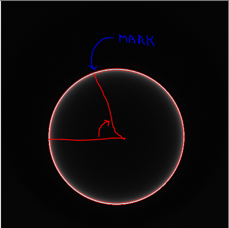
I have a bmp as shown on the seal and a known angle image. I need to place a mark / arrow on the circumference of the circle to the specific known angle.
Is there an automated way to mark the angular location along the circumference knowing the angle with the screw of the Vision?
(The measure in Vision Assistant tool offers a way to really measure an angle between two lines (I think it's what he does to my playing with it).) Is there some emanation of which can be used to help here?)
Thank you
Don
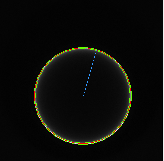
Folks - this is proving to be a very reasonable problem to solve and I had the time today to spend on it.
Here are the basic steps:
(1) (use IMAQ find circular 2 edge to get describtion of circle with RADIUS and Center (use ID or OD - your preference edge until edge strength is pretty good in both directions)
(2) calculate the coordinates of the point circumference associated with angle of interest using VI attached (I had adjust the direction which is the reason why I add 180 degrees from the angle of entry)
(3) use IMAQ Overlay line with coordinates the circumference point and coordinates of the Center
(4) output power line IMAQ superimpose your vision Image
-
How should I store the mathematical variables in Labview?
I am a student studying for a First Robotics Team in the 2012 season. I am writing a program in Labview that gets a measure of angle from two sources, then compares and adjusts the angle of the second until it is equal to the first. The first angle is calculated using trigonometry, and the second angle is picked up by a sensor, we will use the robot. I can make it work when the angle difference 1, but not higher because I don't know how to put loop on himself. If I can store the angle formed by the robot as a variable, it would be much easier.
Is there a way to store a numeric value of input/output as a variable that can be changed by other sources and verified by the program? I can provide the program that I built this day if it would help to explain it.
This specific tutorial covers shift registers: http://zone.ni.com/devzone/cda/tut/p/id/7592
Note that in newer versions of LabVIEW, you can use a feedback node to accomplish the same thing.
-
First of all thank you for anyone who reads this, I am very new to LabVIEW and I think it is perhaps a matter of trival, but I'm not sure.
I am building a test bed to measure the angle of vs couple of clutch disc to find the hystersis. I am confedient that my program is very well to save the data. I am usin a servomotor to apply the couple and when the couple gets to high I want to the plc to turn off the servo motor. I want to LabVIEW for data acquisition, but the plc for the control. I have no experience with modbus. I was wondering if I could share the output by the couple with the plc and LabVIEW transducer or would it weaken my signal and affect my data? The torque converter is a mv/v output, the tourque transducer is TRS - 20K of transducer techniques. I'll use a PLC direct automation and a NOR-9237.
http://www.transducertechniques.com/TRS-torque-sensor.aspx
Thanks for your time
Hi all
I thank very you much for helping out Carl.
Carl,
If you are looking for the cheapest and most reliable solution, I think Dave has a great solution. However, this library is not directly supported by OR so I will be unable to help.
Whatever solution you choose, I recommend always scrutinize watchdog timers.
http://en.Wikipedia.org/wiki/Watchdog_timer
It is a good method to give up your PLC, if the computer breaks down.
Kind regards
-
LabVIEW running very slow over time
I worked on a project at work for a device measuring the ability to couple with a shock absorber. For this, I have two transducers of torque, a small great. And a linear actuator in order to measure an angle using the cosine law. My problem is in the first 30 seconds, the program short grand after one minute or if it starts to slow down. Since this is a test device security is a top priority and I want to keep the delay to a minimum. The digital output in the while loop creates output that closes the linear actuator if the couple becomes too high. Any ideas would be helpful to speed up.
Thanks for your time
Carl
Why you are creating a new task of data acquisition for output within the loop itself at each iteration? This task of creating before part of the loop.
You have 3 tables that you build permanently in the shift registers. As they grow, the computer must be always more large chunks of contiguous memory for storing these tables. I'm surprised that you're having problems after only 30 seconds, but not surprised you are having problems in the end. I bet the reason why I listed above is the reason why it is happening so fast.
Try to use the producer consumer archtitecture to pass the values to a parallel loop and write the data for the file condinuously it.
I see in your instructions, that you tell somebody to hit the Cancel button to stop the execution of the code. It's always a bad idea. You should design your program as a machine of the State where you have different States for the race and setting up different settings. A user should never hit the Abort button (you will fail to properly clean tasks). And they should never really need to hit the run button or once the application is compiled into an executable file.
-
Sharing of Boolean values across while loops
I'm new to Labview and I try to use an angular encoder as a type of switch.
I want to take measures continuously from the angle of the encoder and turn on an analog output signal, each time comes in a certain angle. When the encoder drops from this angle, I need the signal to turn off.
To do this, I try to run two parallel while loops. We measure the angle of the encoder, while the latter creates the output signal. What I want to do is to put a logical statement in the measurement loop that will record 'true' if the maximum angle is reached. I try to get that 'real' statement in the loop of generation of signals as a trigger to turn on (using a case structure and the "DAQmx Start Task.vi") output. The question I have, is that the 'real' statement cannot exit the loop to measure up to the end of the loop. But since I'm running it continuously, the loop ends. Thank you.
Create a local variable of the Boolean in anxiety. Right-click on the local area and select change reading. Put this inside the loop else local. If you have a loop that writes to the Boolean value and a loop that reads from the local. Now you can remove the wire that comes from a single loop and feeds on the other. Then your curls will work in parallel (if there is no other dependencies of data between the two loops).
As an alternative to local variables, you can use a queue to transfer data from one loop to the other. A loop (the producer) will write to the queue. The other loop (consumer) reads from the queue. See the examples on the architecture of producer-consumer for more information.


Maybe you are looking for
-
How to open local PDF with the new Viewer PDF files?
I would use the new PDF Viewer integrated into Firefox 19.0 Beta to view local PDF from my computer. But when I try to open with Firefox, instead of opening it with PDF.js, Firefox gives me a dialog box asking "Firefox do with this file? It is not an
-
I get a lot of errors when I start the computer as kernal32.dll.and memory low andvirtual momery canyou help me
-
How to make a post a snip of something that I save and post it on the forums?
the Insert/edit option is not available and the HTML editing I opened does not give me an option to paste a copy of the capture in a forum. I need help because I want to show a snip from my device manager in a forum. I have a Windows Vista 32 bit wor
-
Must use administrater to do almost anything on the desktop
I had a virus and got rid of him, but must have deleated something that I should not have. The only way I can get my desktop icons or anything to work, I have to right click and click on run as administrater what I did and how can I solve this probl
-
How many times do I need to do a system repair disk?
I recently discovered the features to create a system repair disc and an image of the system. I think I should create a new image system after installing, for example, some Windows updates. Yes? But how many times I have to create a repair update di