measurement of continuous degrees
Hello
I have an arrow that revolves around constant point. I measure the angle of rotation of this arrow. When the arrow cross 90 degrees instead of 91 degrees East - 89, instead of 180 is 0. How to make a continuous measurement of 0 to 360 degrees?
THX
Here is a quick sketch. Most likely, you will have to tweak it a bit depending on how you set the angle.
(A lot of your code much easier...)
Tags: NI Software
Similar Questions
-
Hi people,
I have a challenge I'd like to discuss with you and hope to have some ideas and maybe a solution.
I have a systems acquisition (DAQ) Multifunction National Instruments NOR-PCIe-6353 means X-Series!
I would like to generate and measure signals pulse width modulation .
DRIVER:
OUTPUT:
FREQ: 0, 1 Hz - 1 MHz
Duty: 1-99%
Change the setting on the fly
(This works very well and is implemented)
ENTRY:
FREQ: 0.1 Hz - 40 kHz
Duty: 1-99%
Method of measurement: period of semi / ContinuousSamples / AsyncCallback
Here, I have problems I am running only on an Intel Core 2 Duo CPU E8500 @ 3, 16GHz.
And I want to run 2 PWM_IN and PWM_OUT 2
Low frequency work fine!
0.1 Hz - 20 kHz
It is a loopback with
myCounterReader_1.BeginMemoryOptimizedReadMultiSampleDouble (2, myCallback_1, myPWM_IN_1, myPWM_IN_1_Data);
Data = myCounterReader_1.EndMemoryOptimizedReadMultiSampleDouble (ar, on myPWM_IN_1_Data_actualNumberOfSamplesRead);
A higher frequency do not work very well!
20-40 kHz
I get exception Code of State-200279:
Attempted to read samples that are no longer available. The requested sample was already available, but has since been replaced.
Increase in the size of buffer, most frequently the reading of data or by specifying a fixed number of samples to read instead of reading all available samples would correct the problem.
Property: Value of NationalInstruments.DAQmx.DaqStream.ReadRelativeToRequested:
NationalInstruments.DAQmx.ReadRelativeTo.CurrentReadPosition
Property: NationalInstruments.DAQmx.DaqStream.ReadOffsetRequested value: 0
Task name: NI1_PWM_IN_ctr0
State code:-200279
40 kHz, period is 25us = 12, 5 HighTime and 12, 5 LowTime 50% DutyCycle
This means that each 25us I get a reading of 2 samples the HighTime and the LowTime
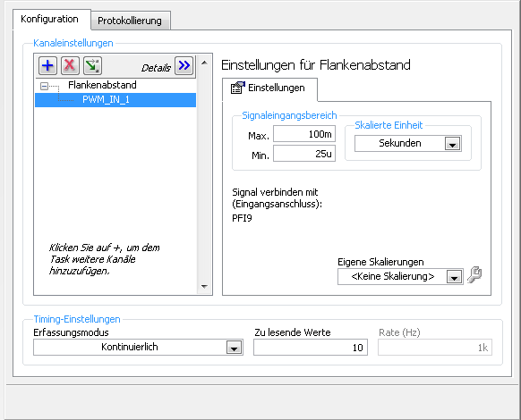
I charge my task of Max, so here's the Setup (sorry its german):
1 can someboby you explain to me what the MemoryOptimized?
2 Zu lesende values means that the size of the buffer 10 is not much but increases the size of the buffer to say 10,000 needing help on
a longer time!
3. playback of data more frequently is not possible because the data are under tension, because it is
4 specify a fixed number of samples I der number is HighTime 2 and LowTime
5. I have does not start and stop the task! Is it better to start and stop the task each time while I still may have a new buffer?
I hope someone has an idea for!
By
Steven
Reading with 50 software we period - bad idea, you will jump impulses. Try to use DAQmx Read Overwrite property, set it to "crush the unread samples" - it will overwrite the impulses without error.
-
How can I measure the continuous component of the tension a SMU-4496 with LabView
Hello
I use an SMU-1073 NI with an SMU-4496 for several applications. In one of them, I would need the blood, maintain the continuous component (this is an accelemeter of MEMS). It's standing vertical, it gives, for example, + 2V and I need to keep reading this almost constant value.
However, with the DAQ Assistant in LabView, it seems that it only reads the component changing signal, as is it doesn´t to move, it reads almost 0. If it moves, the, the DAQ system takes the change but then returns to zero.
Is this normal? Read the constant part of the signal?
(I'm a mechanical engineer and I'm not at all an expert in acquisition of signals or data, so probably just something basic is missing me)
I have attached an example in which, after a change, it goes back to zero and the configuration in the DAQ assistant
Thank you
AC coupling is the culprit-it allows to block all components of steady state DC.
-AK2DM
-
An event, a passage of the different event data, erase them old data
Hi all
I'm developing of movement for a single engine control system. Has been having some trouble, so I decided to simply work the value of the input/output control via control buttons.
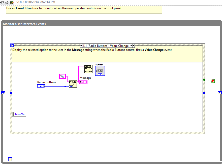
I started with radio buttons example LV then add my bit.
I have two options.
First of all, moving the engine gradually. The user enters the degrees, selects CW/CCW, then GO! Degrees converted to microstep, then multiplied by 1 or - 1 pending management. This works as expected. I bring it in my VI of motor control, data are needed.
The second engine is jogging. The user selects the speed, measures/second (Converts degrees/sec later). Then, they should be able to press the hourly or counterclockwise and the motor shortening until the button is released. The selected speed should stay for the jog buttons until a different value is selected. It does not work. (too bad that my locking may not have the correct value.
What is happening, it is only after pressing the time button, or counterclockwise, erase everything and replaced by 0. Feels like it feeds back?
I tried to use some time in case of loop to continue to send the same value. I have no success. I tried the moving parts of the radio button outside the case of the event and the loop While in hand. Without success.
Any thoughts? The VI is attached.
Thank you!
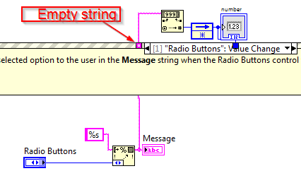
The way you have it, the setting "use default if wired" on the channel tunnel, leaving the structure of event deletes your 'number '.
You must use a shift register to keep the number.
-
Satellite A200 - fan works too
Hello
I will present my problem briefly to you in the hope that I can find a solution.
I work with recording music. My Satellite A200 can handle the processor high and all the rest. I'm really very happy.
But the fan works just too well even when CPU is not used much. I installed The Ultimate Troubleshooter (excellent software) in order to eliminate unnecessary software or process. My RAM is 73% free, low 0-10% CPU and my fan speed is measured at 47 degrees Celsius. My hard drive is 33 degrees Celsius. Very low.
The boring bit, is that my fan is behaving intermittently, but even when nothing is really happening, and the temperature is still very low. I have another laptop to compare to, which is quiet and peaceful in the other corner of the room and only takes action when I activate several operations at once. I wish my Satellite to behave in a similar way.
I cleaned the fans today, and a lot of dust came out. But still the fan curve. I tried to take control using SpeedFan 4.43, but it does not work. I don't see anywhere in the BIOS how I could control the speed of the fan.
I need to find a solution, ideally one that doesn't involve buying a new fan, or disassemble the computer. Since the temperature is right at all times, I guess it's just the BIOS programming for constant speed activity that must change. Any suggestions? It would be appreciated.
All the best, Shlomi.
Hi shlumaan_1,
> I cleaned the fans today
How did you do that? Did you follow the instructions?
How to clean a Toshiba laptop cooling system?There are different reasons for activity high fan and dust that blocks the fan, the thermal paste should be renewed, etc..
Fact is that the fan will be controlled automatically to protect the equipment from overheating. What you can do is chancing the cooling method in Windows power management. I put t know what operating system you use but on Vista and Windows 7, open the power management options, change the parameters of the plan, cooling method. You can change between maximum performance and battery optimized. I would recommend setting the optimised battery.
Also, check the BIOS version. If you have an older version, probably thermal management has been changed with a new version of the BIOS. Update the BIOS that you find on the official website of Toshiba.
Finally, and especially if your laptop probably has a few years, that the thermal compound must be renewed. This is why I would contact an authorized service provider that will apply the correct thermal grease and also the laptop must be disassembled. Not so easy
-
Runtime error example NOR-DAQmx ANSI C in the Windows 7 virtual machine
I am under a guest Windows 7 system with a host of Ubuntu 14, using VirtualBox and have encountered a problem running even the simplest examples provided by National Instruments, using the ANSI C API for NOR-DAQmx.
The first time that the DAQ hardware is turned on, I can run a single measure, and after that, any other indicator displays the following error message:
Attempted to read samples that are no longer available.
The requested sample was previously available, but has since been overwritten.
Increasing the buffer size, reading the data more frequently, or specifying
a fixed number of samples to read instead of reading all available samples
might correct the problem.Property: DAQmx_Read_RelativeTo
Corresponding Value: DAQmx_Val_CurrReadPos
Property: DAQmx_Read_Offset
Corresponding Value: 0Task Name: _unamedTask(0)
Status Code: -200279In order to start a new measurement, I have to restart the DAQ hardware, probably in order to clear the internal buffers that are in the process of substitution.
I am interested in a measure of continuous tension in basic by using a callback function. (The example of ContAcq_IntClk provided by OR)
The exactly the same setup, same version of NOR-DAQmx (9.7.5) and running on Visual Studio 2012 smoothly on a computer that is running Windows 7 directly.
I suspect that the problem is with the internal buffer being somehow messed up because of the connection with the Virtual Machine, but do not find an elegant solution to fix it.
The camera I use is NI USB-6289.
Hello fromm8
Thank you very much for your help, I managed to locate the problem.
He was not the actual code, or something like that, it was a problem of communication between the VirtualBox machine and the physical device.
Kept launches MAX test panels a comparable as error the program C.
I fixed the problem by opting for VMWare, which seems to have the best compatibility with USB devices.
See you soon!
-
State machine with acquisition different modes/loops
Hi all
I did a machine design to State (as described here) to organize three (mutually exclusive) process / States: idle, measurement of calibration and continuous measurement. Calibration must be performed before measurement, because the result of the calibration is used for measurement. The data entry is a camera that should run continuously, also in rest mode.
The problem however is that this state of calibration and continuous measurement (should) have another method of data acquisition. The measure is continuous and the images are processed in real time. To calibrate a number N of images should be accumulated and treated (simply create a background image).
In the state machine as I have now (see attached image), I have the acquisition of vision outside the state machine in order to have a live view at any time. The problem now is that the inner loop in the State of calibration (the loop that must accumulate the framework) accumulates of course that the first framework N times, it is not question for all new managers during this State.
Of course, I could fix this with an if/else statement in the first calibration mode accumulate images (if I< n,="" accumulate="" frame="" in="" buffer="" and="" continue),="" but="" i="" am="" not="" convinced="" that="" having="" a="" lot="" of nested="" loops="" is="" the most="" elegant="" way="" to="" do="">
This also got me thinking, is the state machine, as I built it here all the best way to manage these two processes/acquisition modes? Or are there better ways to do this?
Contributions and comments are very much appreciated!
Note: I know that loop as scheduled now in State calibration is wrong with shift registers. It was a test before I realized that the fault was in the interweaving of the state machine altogether.
Please do not attach pictures, but rather post executable code, screws (easier) or as extracts from LabVIEW (which became the screw when you drag in a block diagram). If you have more than three attachments, compress the folder and attach the ZIP file.
I was once describing a system similar to yours, and one of my students, who was a computer science major, said "it's not a State Machine." I had a similar situation to yours, where I had a procurement process which took time and a 'Stateful' routine that does different things with data (in your case, use it for calibration, waiting to 'Go', absorbent, etc.).
I understood that it was correct. I ' D 'opposite' model, with the Acquisition, always running and "driving", the calendar and make 'Appropriate Action' on each set of data, where the Action could (and did) vary according to other conditions. So I renamed my state machine 'Action engine', and everyone was happy.
So I won't bother looking at your code (a quick glance showed me that I have only would be frustrated by the limited view), but will give you a suggestion for an alternative architecture.
You want to (ideally) two parallel loops. A single loop simply acquires the data (images) at some rate. For each Image, it signals the loop else it's time to 'Action' on the acquired data (to do this, use a queue or the notifier). You want that engine of the Action to perform independently the Acquisition loop, just in case a particular Action takes, say, 1.2 times sample to complete - you don't want 'Miss' samples!.
The loop of the engine of the Action is a unique, appropriate Action at the time, on the newly acquired data. If you are in the 'State' calibration, the Action will be "add to the calibration. When you have accumulated enough data to do calibration, set the following Action to (for example) 'wait to start the Signal. When you receive the Signal to begin, take Action to "acquire, process and save data. And so on.
As it happens, I did my code exactly in this way, but it was the idea General - Acquisition was the 'King', he ran the clock and led the ' Machine/Action State engine' to 'do the right thing, appropriate to the time' with the data. See if this type of model is appropriate in your situation.
Bob Schor
-
Hello all, first post here,
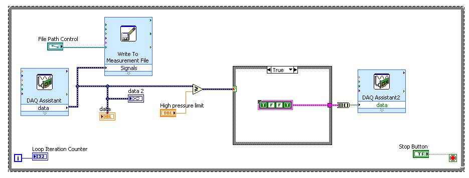
What I have is a VI that measures pressure continuously from a cDAQ 9237 and folders in a file. What I need is to do is to react on this feedback to open/close data 4 solenoids both needed a cDAQ 9481 for this project, I need to fill a ship on a cyclical basis to + 2 then cycles-2 lb/po2 for 100 k. So far, I have solved this problem for a two State or limit level system as indicated below.
I think I need to expand this concept to the State of a multiple system a 'fill', 'Empty', 'Hold' (and probably a State initialization and purpose as well) who is selected by the feedback data. I think if I do all this with logic and limits, I can't always custom if its time to fill or empty the tank, so a kind of sequencing is required. At some point, I'll add a counter on one side of the cycle for counting up to 100 k bar and complete the test.
You have any suggestions on how to achieve this? I'm puzzled.
Thank you
Ken
"I hope I can count every instance of wedge of high pressure. I think it may have something to do with local variables, but not him have not yet solved. ' Add a record to offset which is incremented in this State. (A node of feedback would be more clean!)
I'm also fighting how to implement a short break after that occur in wait States; Look for the vi time delay on the pallet of timekeeping
-
Entry of absolute encoder PWM w / 6008
Hi, I'm quite new to the DAQ world so please be easy on me.
Well basically, I have acquired a free 6008 and want to use it to track the absolute deviation of angle of a device I have.
My scope involves the use of a labtab (USB only), as well as a range of measurement 0-90 degrees with an accuracy of 1 degree at most.
So I came to the conclusion that I have to get an absolute encoder.
Watching the encoders and their respective exits, I found the following: SSI, Linear Voltage (0-5 Volts) and PWM
I have falling SSI my list because it seems a PCI data acquisition card is a requirement, and the linear voltage is all simply not precise enough, because the encoder outputs (0.056 volt/deg) and the 6008 can be read only with accuracy intervals (0,138 volt). Which means (2.484 degree/interval), I think.
in any case, the last style of output that I found was the PWM signal.
The encoder http://usdigital.com/products/encoders/absolute/rotary/shaft/ma3/
If I have good outings (at intervals micro-sec 1026), where the duration of the pulse is the position of the encoder. (1026 counties/revolution).
So I guess I have to be able to read the pulse of the order (1 micro-sec) for (1 head).
My question is whether or not the 6008 is able to acquire the data for my use in LabView.
Counter the 6008 says its able to detect more than (0,1 micro-sec) pulses.
Does this mean the 6008 so capable of doing the job?
Any help is grateful, as I have very little experience with LabView or DAQ instruments.
Thank you.
It is a limitation just to the meter of a USB-6008. What you describe with 2 counters is actually very close to what we do for measures high frequency on our complete recommended counters. The pulse actually measure that requires only one meter on our E-series, M-Series devices, meter Timer and X-series.
In regards to the analogue output of the absolute encoder, I think you should be ok with the resolution. The output of the encoder is 0 to 5V. The typical accuracy on the 6008 for this interval is 4.28mV for differential connections. Step for each degree size is 5 /(2^10) = 4.88mV. Thus, it seems that you will be able to get a precision less than 1 degree.
If you need better accuracy or would prefer to make the PWM output type, I would look at our M-Series USB for a portable data acquisition solution. Let me know if you would and I'll give you a few recommendations.
Regads,
Paul C.
-
events producer consumer with notifiers
Dear users of LabView,
I would like to ask your advice on my project (see the attachment of files). For the beginning, I did only the "backbone" of my project, that's what you can see in my VI. My project will have the following features:
-Start and stop action possibly (and also plot data to the chart and saving the data to the file)--> here is some time a loop to record data ranging from DAQmx (USB6009) and another while loop with rates of different loop to rise in voltage output amplifier of the magnet.
-During the measurement, or if the system is idle, the user is able to read files of measured data and evaluate the measured data, etc... (so there will be more features...)
I decided to use producer consumer structure with events and the authors of notifications, and I also use the dynamic user event to be able to communicate to the consumer with the producer (where I have my machine of the State as in a shift register).
Please comment on my VI, what do you think? Maybe I should use the state machine (the shift with the pole of the State Register) in the lower loop? I could also use up queues of the notifier, but since I send only orders and the values of the parameters (not streaming broadband data) I guess that the declarant is fine?
Thanks for the tips!
The code you posted looks like a good start. The architecture is very similar to the measurement sample continuous project comes with LabVIEW 2012.
A few things I noticed:
- I would usually use queues instead of filers (unless you want to manage only the last command and not all orders in the order they are received).
- You don't need the registry change in the top loop (structure of the event). You inadvertently send a length of measure and other commands parameter since you replace only the command. Probably, this is no problem for now but could be a problem later.
- I think the user events are a great way to manage cases of judgment where the consumer is able to report to the producer that the application must exit loop (this is how we do in the sample project).
- Your case 'Init' confuses me a little. It is read length control measure and send a user event in the event that, in the structure turn immediately place a measure command. Once I see a control in a loop of consumer as it hurts a bit uncomfortable. Why not have the value "start_measurement" to change event read the length of measure command and send it as part of his message to the consumption loop. Then the loop of the consumer can Init and self talk to start the measurement.
- You may need to rethink your strategy mistake in the case of the measure. Currently you do not stop a loop if an error occurs, and allows you to keep the error between iterations of the loop information shift registers. Therefore, if an error occurs in one of these loops you can never hear about it.
- In general, using the error state as the main way to stop a loop from consumers is a bad practice. I'd rather see a "Shutdown" command which causes the consumer to stop loop. It is more scalable and less likely to be triggered by the accident.
Good luck with the rest of your application.
~ Simon
-
Impossible to acquire constant values on FPGA in CompactRIO.
Created a VI to acquire data from the analog input NI 9201 on the target FPGA CompactRIO 9004 and chassis 9014 module. We used DMA FIFO to transfer the data to the target FPGA for the RT. RT, read us this FIFO and then forwarded the data to the binary file to nominal vi. A possible problem could be that the binary file for vi nominal is acvquiring of the fixed point directly from the read FIFO data and therefore wrongly calculated. So we put indicators after reading the FIFO to check the values of fixed point. A constant supply of 5v has been read 4-5. But there are a lot of unreasonable variation. Is there another step I need to take to convert this binary fixed point? Is there something wrong with the FIFO DMA timeouts? I enclose all relevant VI.
Hello
What is the range in which the values are different? Also put a low-pass filter will help reduce the noise, if you want to measure the continuous tension only.
-
Desperate! Captivate4 crashes when you try to close
Hi all. I'm desperate! This bug caused me severe headaches, and I have no idea what to do about it.
The fault is as follows. Sometimes when a user clicks the black 'x' in the standard skin of a captivate e-learning I, the window will not close. The user expects 10/20/30 seconds, it does not close again so they close the window using the "x" browser, and the score is not sent to the LMS. The only way I managed to fix this is by removing the e-learning and the Uploader on the LMS again for the LMS starts a new record for this user. Once it is glitched once for a user, the LMS file seems to be corrupted, and it will not correctly mark unless that e-learning is deleted/downloaded again.
The strange thing is, if I look at the interactions between Captivate and the LMS with the Firefox plug-in (don't remember the name) I can see sent scores that I am progressing through online learning. When he 'glitches' as explained above, Captivate sends all the scores again, one at a time. This seems to be an overload of the LMS, that responds to each message. If I let you carry by the whole process then he will finally close the window and the score will be precise, after 15-20 minutes!
The LMS is a cleaner, not a generally available, but I'm sure that it is fully SCORM 2004 compliant, which is the standard that I use for the Captivate. I tried to convert my Captivate in AS3 (currently 2), using a button javascript to close the window and using Litebox but nothing makes a difference. All attempts of 1 to 10 I'll have this slow issue of closing.
The captivate itself doesn't have a quiz, but about 70 measurable objects ('continue' buttons). If the user is not to fill a captivate in a series of modules I published, they cannot move on to the next (these requirements are controlled by the LMS, PROVIDING captivate sends the score of successful completion).
If anyone can help me with this I would really appreciate it. I still don't know if this is due to Captivate, or LMS. LMS people are pretty useful, but unfortunately cannot justify spending a lot of time on it because no one else has reported problems. Only me, using Captivate...
Thanks in advance.
Captivate deluges LMS with information about each user interaction.
But you can use a special model of HTM for SCORM, which sends only marking the information at the end of the module. It relieves a lot of load from the LMS and may help your problem.
This model comes standard with Captivate 5.5, but earlier versions of Cp can also use.
Details here: http://blogs.adobe.com/captivate/2011/04/a-new-way-to-report-scores-to-the-lms-from-your-c aptivate - courses.html
If you use a LMS system, I would also say that you disable the close button in the skin anyway. You ask for trouble he leaves. If you are using the SCORM LMS drive. some LMS work best if you set up the SCO to play in the same window as the LMS TOC rather than in a separate browser window. Have you tried this option? It seems allows communication between the reader and the SCORM API in the HTM page course.
-
Prepare an image in a printed canvas
Hello
I'm all new to photoshop. I am preparing the images to go to the printer in the wrapped canvas prints. My 20 "x 30" should have a 1.5 border"all around. I've seen prints that were a reflection of the canvas or blur in the 1.5 border "that ends up being on the side of printing wrapped. How to do that. Thanks in advance
If I understand correctly you have a 20 "x 30" file that you want to add 1.5"bleed all around to make it 23 in. x 33 in., and you do nto want to scale of the original.
- Canvas image size 23 "x 33"
- CMD J float a copy
- Edit > transform > flip horizontal
- Layer to slide over
- Repeat this operation for the other 3 edges.
- CMD T on each new layer and command drag 2 corner to get a measure of 45 degrees in edge
- merge the 4 layers use patch tool or clone tool to fix the angular corners
-
Amplitude measurement of a continuous signal in a given time window
I'm working on an acquisition system that acquires a continuous signal of 250 kHz. My goal is to measure the amplitude peak-peak of the first reaction of signal, the problem with my setup, this is the first part of the signal is always higher than the part of the signal that I'm interested. If I try to use the measure of max from Ridge to ridge of signal VI then responds with the measure of Ridge Crest of the initial part of the signal. See the attachment for a better understanding, I would still like to view the raw signal as is, but I would like to measure the peak voltage at peak of the signal between the yellow sliders.
Thanks in advance...
If transient initial always occurs in the first 12 microseconds, you can use any subset of table or similar wave function to retrieve the last part of the wave. Then use the measurement from Ridge to Ridge on this subset.
Lynn
-
Scaling of the continuous measurement and logging (OR-DAQmx) model
Hello
I managed by reading the analog input of my 6210 USB and NO using the model of logging (OR-DAQmx) and provided continuous measurement. However, I need to convert the voltage signals to the pressure.
How I change the model to achieve this? I've read about DAQmx create Scale.vi and creation of scales in MAX, but I'm not sure where/how to apply them to the model.
Fine thanks
Ben
In the loop Message of Acquisition VI is a case to launch Idle. Here is where the task of data collection is initialized. In both of these screws is where you add the code to create the scales and apply them to your analog inputs.
Maybe you are looking for
-
Firefox will restore private after an accident browsing Web sites?
I was in private browsing and Firefox crashed. If someone else uses my computer just after the crash, 'restoration' firefox session restore websites visited in private browsing?
-
What does say when I get the message that says "No VGA Signal"? Do I need to replace something?
-
Type of adapter antenna tv for Qosmio F30-140
Hi all I have a F30-140, which came to me without the antena tv adapter.This model is not imported and officially supported in Bulgaria, so I am unable to find the adapter.Already browsed the site of support of the United Kingdom, but they do not off
-
Microsoft updates has become unresponsive. __
Microsoft updates have been installed on my laptop, they have become desensitized. I closed my laptop. Now, windows Explorer does not work. How can I fix it?
-
How to add an A. REG manually?
I'm used to double-click a .reg file to add to the library to register. But now in Vista, it just opens in Notepad. How can I add the .reg file manually (like a double click does nothing)?