USB 6008 angle measurement?
Hello friends
I need to measure the angle of rotation of the shaft with a precision of 1 degree... is there any simple device can I connect with usb 6008 custom angle...
Thank you
180 degrees is very different from continuous rotation. Just wire a potentiometer to one of the analog inputs and try to calibrate it.
You don't need the LM317. It will not help you with what you have described so far.
Lynn
Tags: NI Hardware
Similar Questions
-
NEITHER USB-6008 can measure an AC voltage
Now I am doing a project, but don't know if DAQ can measure an AC voltage or not, the acquisition of data that we use is USB-6008.
Yes, it can measure AC in the range of +/-10 volts and have a sampling rate of 10kS/s.
Application engineer OR
-
USB 6008 weird analog voltage reading
Hello
I use the USB-6008 to measure a voltage of a Lithium battery, 3.66V.
the battery come with a blocking diode (in series with the battery) of 1N5820, who have a fall of voltage drop of 0, 1V.
battery with diodes in series (this is the way in which the battery is shipped with)
-measure with DDM yield 3.66V without you connect to usb6008
-measure with DDM yield connected to usb6008 (putting OUT VOLTAGE USB6008) 3.59V
-able with USB-6008 performance 3.59V connected to usb6008
battery with diode removed
-measure with DDM yield 3.66V without you connect to usb6008
-measure with DDM yield connected to usb6008 (putting OUT VOLTAGE USB6008) 3.66V
-able with USB-6008 performance 3.66V connected to usb6008
Thus, it seems that the problem is in the led in the series. This is why the battery voltage has fallen to 0.07V? the series diode will hurt the USB-6008?
Maybe people who know the circuits inside the USB-6008 can give me an answer.
Thanks in advance.
Hi learnerd,.
The fall that you see is falling forward in the diode. As an entry class device, the USB-6008 case has a relatively low input impedance (144kOhm) and thus draws a little current of the device. Looking at the datasheet of the 1N5820 (http://www.onsemi.com/pub_link/Collateral/1N5820-D.PDF), Figure 7 shows that at 25 ° C, a draw of 50mA will cause a fall front of 200mV. While the figure does not extend the curve below 50mA, extrapolating the given curve would indicate that a drop of 70mV would cause only a few current microamperes.
A DMM will have a much greater input impedance (GOhms instead of kohm) and won't draw enough current to influence the measure, that's why you wouldn't see the decline with only the DMM.
The diode will not harm the USB-6008 somehow.
Good luck with your application,
The f
-
Beyond the limits of voltage on USB 6008?
I use a USB-6008 to measure analog differential in the range of 3 to 5.3 V. I chose this range, because outside this range, I'm not interested in what the tension is, knowing that his "on the rail", but to aid resolution of the ADC in this range.
So for a signal of ~0.05 supply V, I expected to read 3V, telling me that the voltage is lower than 3V, but again it returns 0.05v?
As it was unexpected for me, could someone please explain what can / should I expect of my USB6008 of the responsed to the signals that are the limits? Is there an effect of "rollover"? Should you return the value to the limit? Depends on how far the limit is?
Thanks for your help!
Entry level do not think that way. You specify the range is that you wait for the signal and the DAQmx driver will set the most appropriate range that the device supports. The actual ranges are indicated in the guide. In your case, because you specify a max of 5.3, the device would be defined the +/-10 volts range.
-
New to Labview, need help. USB-6008
Hi there, let start by saying, I'm totally new to Labview. I have experience of programming in C, C++, VB etc, but never in Labview. I thought that Labview is not much of a difference, but I was very wrong. I went and bought the acquisition of data USB-6008 and downloaded the trial labview to explore and I am totally stuck and have no idea how to proceed. I can start over again and probably learn all the basics, but I don't want to take too much of my time. in any case, here is a description of my project:
Configuration: USB-6008 - to measure the voltage of a battery lithium ~3.6V
Circuit printed with a switch either connects the battery resistance or not. the switch can be turned on and off by a USB-6008 analog voltage output
What I want to do in pseudo-code:
If you click START,
Take a read of DAQ and shop to chart and indicator of voltage 1
If the voltage is > 3.6, then
30 seconds
a voltage data acquisition to turn on the switch and light load lights output
read DAQ and update graphic and indicator of voltage 2 reading
If it is DAQ< 3.5,="" status="" indicator="OFF," else="">
30 seconds of the end loop
If the last reading after 30 seconds of DAQ is > 3.5, the message 'pass' else a message "fail".
on the other
indicate a voltage lower than 3.6V and stop the program
end if and stop the program.
NOTE: the voltage indicator 1 show ONLY the first reading before the circuit switch is on.
I didn't know that it is very difficult to program, because everything is very basic, but since I don't know Labview, I do not know how to proceed. a front is attached.
Thank you for your help.
John
Hello!
To start, here are a few things.
1. learning LabVIEW:
This has all kinds of videos step by step based on LabVIEW and is a great resource just start... it's really great because you can click on a video about any topic that interests you. There are a set of tabs at the top that categorize videos.
2 examples of DAQ. In LabVIEW go to the Help menu > examples of find... Then in the window that opens (this is called the Finder of the example) you can navigate to the material file Input and Output > DAQmx > Analog measures > voltage
We have tons of DAQ examples, so this should at least allow you to read a voltage quickly.
I hope this helps!
-
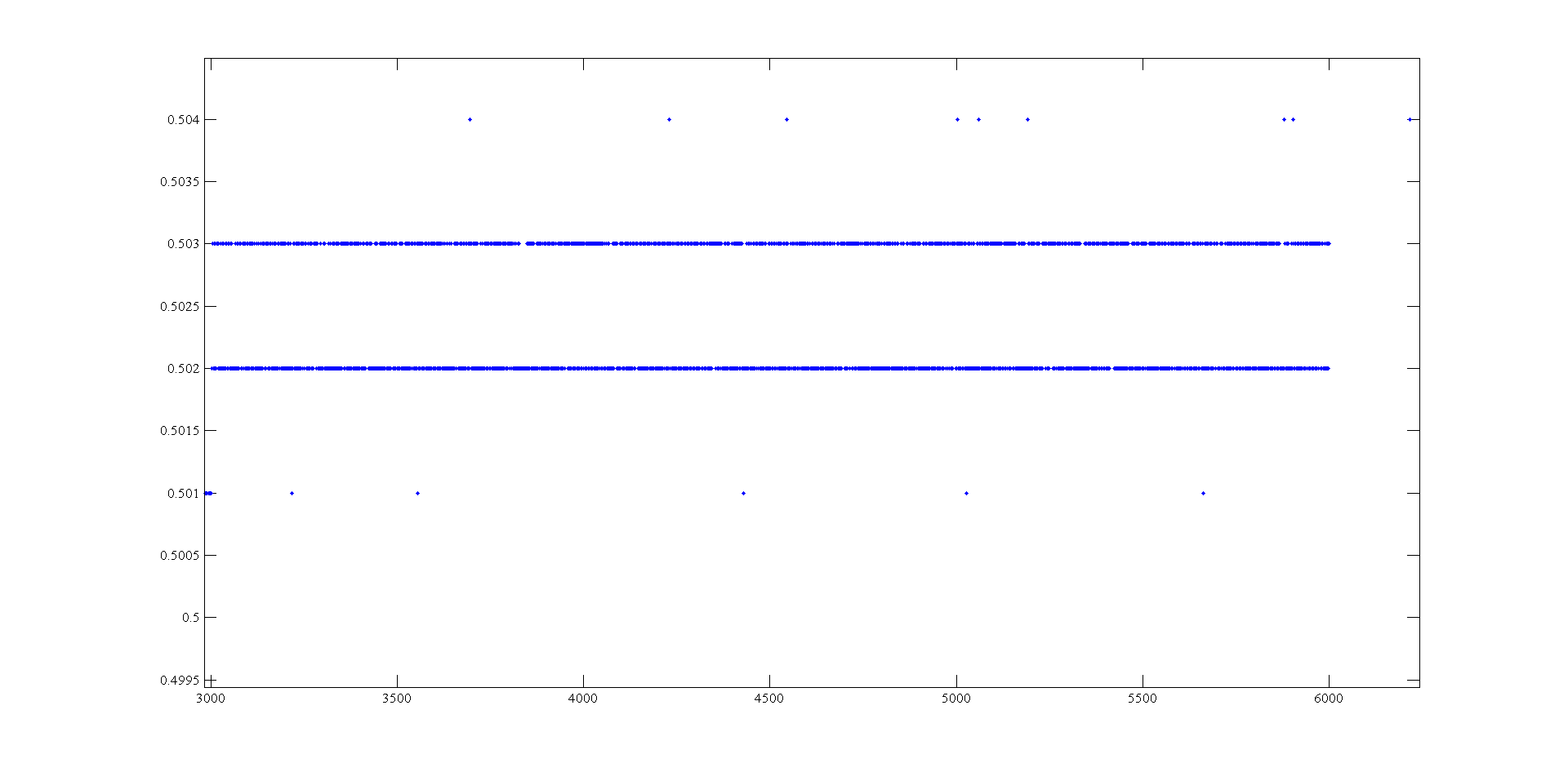
Measurement of voltage USB 6008 ranging from 1mV
Hi, I'm doing a supply at an angle for an amplifier using the USB-6008. The ranges I look are - 0.5 to 0.5 V and 0.5 to 2.5 V. To generate negative tensions, I use the + 2, 5V for a reading of differential voltage output as a 'ground '. Voltage measures have a delay that varies with the voltage, given this by drawing these variations and set the output to data acquisition there is still a 'noise' of +/-1 mv so that it is clear from this parcel of tension against the sample number:
It seems that at some point the values are being rounded up to the nearest millivolt. I need to get to a resolution of 0.5 mV for my device, it will be possible with the USB-6008?
The AO USB-600 x has a range from 0 to + 5 V and the 12-bit resolution. 5/4096 = 1.22 mV. Absolute precision is 7 mV typical and 36.4 mV maximum full scale. The noise of the AO is not specified.
If you measure the results with THE USB-6008, you have at least 0.5 mV, similar resolution system noise and absolute accuracy of 2.5 mV or more.
It's probably as good as you will get with the box USB-6008.
Lynn
-
NEITHER USB 6008 voltage offset using CSR and measurement of diff.
Hi all
I am currently trying the NI USB 6008 housing and I'm getting problems when reading voltage analog using CSR or differential.
So basically, what I want to measure is a PWM signal (0 to 12V), which is divided by a divisor of tension (by two). But instead of measured 0V and 6V
I am in a position a constant 0.8V and approximately 3V.
On the side of digital data acquisition, I give you on impulses for the SSR... and it works fine.
I connect it that way: http://digital.ni.com/public.nsf/allkb/95CC0CB11D7DF3D18625712E000C4ABD?OpenDocument
Would apreciate any help
Best regards
EDIT: Attached graphics acquired are
What is the impedance of your voltage divider? The input of the USB-6008 impedance is not very high. If the impedance of the partition is large, it could cause the effect you see.
Lynn
-
Want a ramp of output voltage over time and measure input 2 analog USB-6008
Hello
I want to produce an analog voltage output signal that increases over time with a certain slope, which I'll send in a potentiostat and at the same time I want to read voltage and current (both are represented by a voltage signal) that I want to open a session and ultimately draw from each other. To do this, I have a DAQ USB-6008 system at my disposal.
Creation of the analogue output with a linear ramp signal I was possible using a while loop and a delay time (see attachment). Important here is that I can put the slope of the linear ramp (for example, 10mV/s) and size level to make a smooth inclement. However when I want to measure an analog input signal he's going poorly.
To reduce noise from the influences I want for example to measure 10 values for example within 0.1 second and he averaged (this gives reading should be equal or faster then the wrong caused by the slope and the linear ramp step size.) Example: a slope of 10 mV/s is set with a 10 step size. Each 0.1 s analog output signal amounts to 1 mV. Then I want to read the analog input in this 0.1 s 10 values)
Because I use a timer to create the linear ramp and the analog input is in the same loop, the delay time also affects the analog input and I get an error every time. Separately, in different VI-programs (analog input and output) they work fine but not combined. I searched this forum to find a way to create the ramp in a different way, but because I'm not an experienced labview user I can't find another way.
To book it now a bit more complicated I said I want to measure 2 input analog (one for the voltage of the potentiostat) signals and one for the current (also represented by a voltage signal) and they should be measured more quickly then the bad of the analog signal. I have not yet started with because I couldn't read on channel work.
I hope someone can help me with this problem
An array of index. You want to index the columns for a single channel.
-
DAQ USB-6008 will be able to power and record voltage for UMS T5 blood pressure at the same time?
I would use my NI USB-6008 to power my blood pressure monitor UMS T5 (http://www.ums-muc.de/en/products/tensiometer/t5.html) but also to take readings of it, but I don't know if it's possible to do it properly. The power supply for the instrument can be as low as 5V, I can easily get the dedicated + 5V channel. I'm able to feed the instrument and connect it to an analog input on the 6008 and measure a voltage in differential mode. However, when you read the documentation of support for the instrument, I find the following:
"Potential pitfalls of data acquisition: the pressure transducer is configured in a full Wheatstone bridge, the input voltage and mV signal output can be connected to the same reference (mass)." Therefore, the mV output signal can be measured using a differential voltage measurement. Therefore, do not make an asymmetric measure of pressure transducer mV output. "(http://www.decagon.com/assets/Uploads/MeasuringUMSTensiometerswithnon-UMSControlandDataAcquisitionSystems.pdf)
My understanding is that the 6008 can take a differential measure if I attach the signal '+' and the signal "-" to the analog inputs of positive and negative terminals. However, it seems that all the ports of ground on the 6008 are grounded to the same reference, which would make my measure of invalid tension according to the above paragraph. So my real question is: if I try to record the voltage with one of the analog inputs on the 6008 in this way, is the valid measurement? Or I need to find a separate power supply, with a different reference field to ensure that the measure is accurate?
The technical details of this device is very poor. The manual is not much better. Companies that want to sell scientific equipment should publish decent cards or get out of business.
In section 3.4.3 General requirements the device is described as a "bridge not amplified circuit. This information along with the impedance of the bridge should be in the specifications, because it is essential to apply the device under any circumstances other than the nominal behavior in 10.6 V.
The answer to your question is:
You can use it with the box USB-6008. The 5 V supply will result in output voltages a little less than half (5/10.6) the voltage specified in nominal conditions. You can use the differential input mode on the box USB-6008. The absolute input voltages will be approximately 2.5 V with the 5 V power supply. This voltage is in the range of the aircraft. The differences are likely to be less than 100 mV. The resolution of the USB-6008 on the + /-1 V is located about 0.5 mV so your resolution of pressure will be about 1% of full scale. The voltage input impedance and termination of the USB-6008 will present a few errors. These can be in the order of 5 to 10%. I can't predict much better without the missing bridge impedance specification. These errors should be relatively constant and systematic. A calibration of the whole system - sensor and together hardware DAQ should allow you to compensate for a large part of this error.
Lynn
-
Input/output USB 6008 test failure
OK I am posting this for the third time, but whenever I go back to the home page of the forum, I'm not able to find my post. If by chance I created duplicates than apologies.
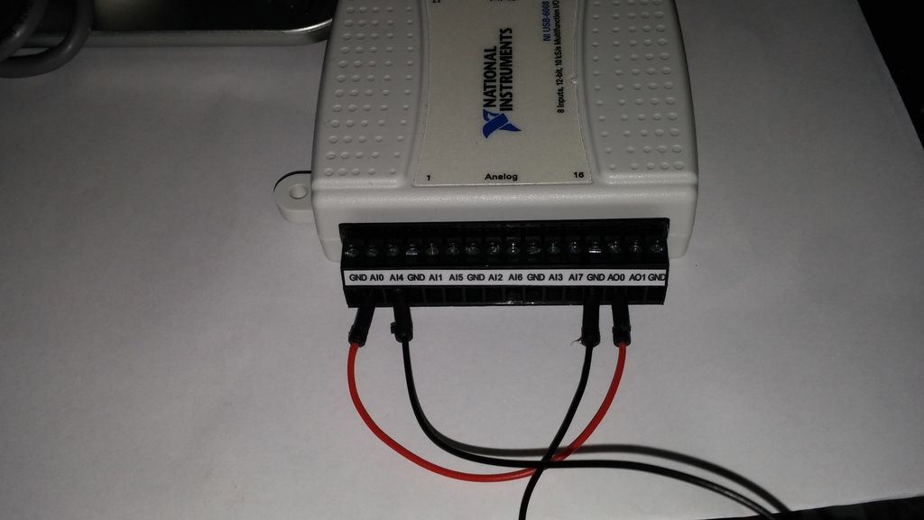
IAM in train to test the USB-6008 case I just got and decided to hang the analog of the analog inputs and see using labview VI.the wiring was done as:
http://i284.Photobucket.com/albums/ll5/bigdawg6/USB%206008%20wiring_zpss2b7hql9.jpg
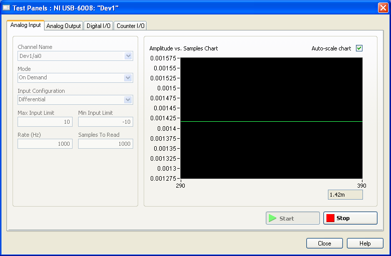
the problem is that the labview VI did nothing, so I go to NI Max and try to see in test panels. But I get 1.4V constantly my same analog input value when I'm changing my analog value:
http://i284.Photobucket.com/albums/ll5/bigdawg6/AIO%20screenshot_zps9beiimbj.PNG
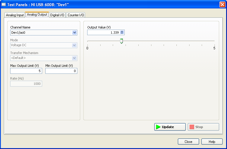
the analog output works very well since I plugged it to my multimeter and I can see the tension that I see on this Panel of test:
http://i284.Photobucket.com/albums/ll5/bigdawg6/AO0%20screenshot_zpsqpei37bw.PNG
I created an entry/exit of the tasks; screenshots of them are:
http://i284.Photobucket.com/albums/ll5/bigdawg6/task_ao_zpsykmvczew.PNG
http://i284.Photobucket.com/albums/ll5/bigdawg6/task_ai_zpsix5se9yg.PNG
I am quite frustrated with all this since I'm unable to access my actaul draft. I know that 1.4 V value is from the device itself; as in the manual it says 'internal resistance divider can cause the Terminal to float at about 1.4 V when the analog input terminal is configured as a CSR', but the funny thing is that I use it in differential mode so I don't know what to do and any help is appreciated.
BTW, I did a google search and there are other tutorials onlune who seem to do exactly what I do and they seem to work very well; so I don't know what else to do.
Please don't host images on some odd third-party site. Attach them to your message.
I don't understand what you've done. The 6009 can produce only a signal of CSR in order to set up the differential input makes no sense. If you want to measure something different, try a simple battery.
-
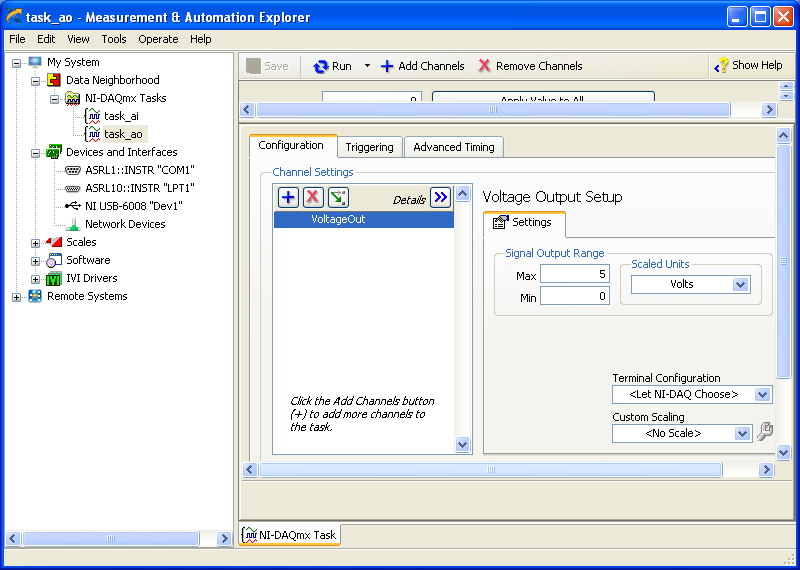
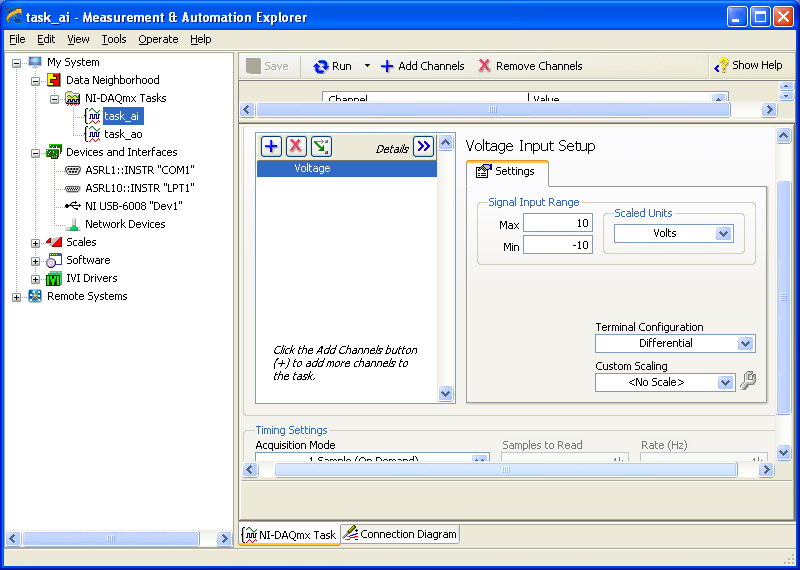
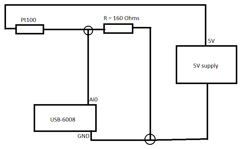
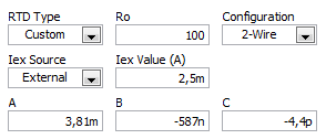
Pt100 (USB-6008) configuration problems
Hello
I'm using the hardware DAQ USB-6008 (I know that's not accurate and all) and I use the Pt100 (QAP2010, click for plug technique).
I connected it like this.
Now in LabVIEW, these are the only options (DAQmx new task-> acquire->-> RTD temperature signals).
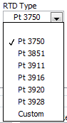
If I choose for custom settings, I get these options (I don't know what variables that is).
I use a small greenhouse where I need to measure the temperature and humidity and control environment (by using a fan to cool the cartridges to greenhouse and heat to heat).
My goal is to read the temperature using a graph on the front panel.
Can someone help me how configure/choose the right options? If you need more information I'll provide them as soon as possible!
A quick search for RTD class B shows the precision and the coefficient. As Fan Ravens stressed resistance according to the temperature is plotted in the data sheet. To control the temperature in greenhouse, a simple calculation of the slope of this graph is not good enough.
Note that the USB-6008 case limited an active player on the outputs analog and it controls only the voltage. So you will need at least one external resistor and possibly and external power to excite the RTD. These options that you have linked is not applicable to the USB-6008, which is a very simple device. You should perhaps simply to measure the voltage and calculate first resistance, then the temperature.
Lynn
-
USB 6008 digital output signal
I am VERY new to LabView and have been racking my brain trying to get digital output of my USB-6008. All I want is to be able to get a signal of + 5 V of my digital output when I click on a button. This signal opens a valve on a system I see so when it is pressed, it must stay open until I press the new button. It seems simple enough to me, but I'm not too familiar with LabView. Help, please!
Stripling07
You must first take the LabVIEW tutorials and then look at the links to get started with DAQmx .
The simplest program would be with the DAQ Assistant. Drop it on your schema, and then select digital output > digital line. Select the line when the wizard has completed, click OK. Wire a Boolean value in a table to build and the output of which is connected to the data entry. That's all. You can test the output of MAX (Measurement & Automation Explorer) with the test Panel. Do NOT test with your connected tap. Your valve may require more current that can provide the 6008.

-
NEITHER USB-6008 connect to thermocuples and pressure sensors, control valve
I am endevoring to build a gasification plant biomass for bench scale test process control plans. NEITHER USB-6008/6009 will be adapted for use as a data acquisition. I'll take RTDS, thermocouples and pressure sensors. I don't want to use industrial automation controllers. It is also possible to use the channel of analog output for sending signals to a control valve position (using sufficient current/voltage between the two drivers).
(1) OK. I just wanted to be sure that you were aware of the potential dangers.
(2) an RTD is a resistance that has small changes in resistance per degree of temperature change. To measure that you have need of a current source and a sufficient resolution in order to detect small changes. At 25 degrees C a typical RTD is 109,73 ohms and resistance ohms 0.38 per degree changes. If you had 1 my crossing this RTD voltage through it would be 109,7 mV and the voltage change of 0.38 mV by degree.
The resolution of the 6008 on the most sensitive range is 0.49 mV > 1 degree. The accuracy of the 6008 is 1.5 mV typical.
For a Type K thermocouple, voltage at 25 degrees is 1.407 mV and change by degree is 39 µV. Millivolt solving half of the 6008 translates into about 12 degrees.
If you need a source of excitement for RTD and a kind of amplification for thermocouples and RTD before she would make any sense to try to use USB-6008.
(3) I have not used anything except LabVIEW with DAQ devices and drivers. I think DAQmx can be used with MATLAB and other languages.
(4) the 6008 is the low range made by NOR. You will need to go to a more expensive camera or add signals conditioning circuits. Talk to your representative OR assistance in the choice of a suitable device.
Lynn
-
fiber optical sensor su19 110 115 a 126 vs nor usb 6008
Hi expert... I am looking for idea or help on my project. I try to get the measure of mention nor USB 6008 sensor output. In fact, I'm new with nor peripheral usb n still study n the search on internet or n. forums I found an idea to connect the sensor by aoi, but I can't seem to get a measurement any. Is the sensor can connect directly to the device usb or need some custom wire diagram between them. Thanks in advance
First of all, it is useful if you name the manufacturer of the sensor. A single part number means nothing to most of us. You use the sensor fiber-optic Pepperl + Fuchs? Even better is to display the technical/manual plug of the sensor or links to them.
The data sheet that I found for the sensor to Pepperl + Fuchs is not very well written, in my opinion. It seems that the outputs are impulses with dependent amplitudes of the voltage and the frequency or the timetable set by the mode of operation.
If it's the device you use, the only way you have any possibility to decode the outputs with the USB-6008 box is to measure with an analog input and then process the data in the software. According to the supply voltage, you will probably need a voltage divider to reduce the output voltage of the sensor to a level compatible with the DAQ hardware. You also won't be able to use the high speed of the probe because the heart rate exceeds the Nyquist limit. In standard mode, you mighte be OK, but you can use a single channel of the USB-6008 to stay in the Nyquist limit.
Lynn
-
Get incremental counter/sound to work along side with action with usb-6008 with labview tia sal22
Get incremental counter/sound to work along the coast with usb-6008 with labview tia sal22
Hi all
I can get this vi to work if they are distinct from the vi but I can't join them together
Example of my error:
If buffers are set to 0 the freq counter increment works, but no sound
If the buffers are set to 1 the audio works fine but is not increment the Freq counter
If the buffers are attached to more 1 clicks and pops are comingThat's what I'm doing:
(1) have the frequency of increment of my internal sound card to a certain level as .01hz a second until he gets to 20 000 hz(2) use my device usb-6008 daq, which is connected to the same machine to measure the voltage at the same time. (I am in a position very low voltages between 1-5volts)
(3) output to a worksheet text file which will show you:
time in seconds, frequency, voltage
0,400.01,21,400.02,2.5
2,400.03,1
I'm a bit confused about how connect the increment and the audio during the measurements with the usb-6008 housing on the same machine
at the same time and in the same VI.Anyone have any ideas? I'm using labview 8.5
TIA sal22Ha ha you have been deceived by a dynamic thread. Insert a convert from Dynamic Data Express VI (Palette to own: Signal handling screw Express) between the daq read and build the array function. Then it won't work. Now the value in the dynamic data is only converted to a numeric value
Maybe you are looking for
-
XPRT: "Camera" and the issue of sounds
Hi - I have a few questions that I can't find answers to anywhere on the web or in the documentation. Is the button that is currently associated with the calendar, possible to associate it with the camera function?Where do you turn the sound on the c
-
A MK-8025GAS HARD disk will fit in my M10 Pro Sat?
I think my laptop satellite PRO M10 HD upgrade but I do not know if the Toshiba 80 GB HD MK-8025GAS fits well inside the laptop. would be any problem of pins or something similar? I did look at other Toshibas not HD and they are not due to external H
-
need to get the part number for fan of cooling of the laptop dv6 of my desire
s/n [number of Series edited by Moderator] p/n C2L44UA #ABL less than two years old fan cooling makes rattling noises now, check the dust, cleaned air jet led, the still small makes fan noise rattling sound, need to get the part number and get a very
-
master code please 69639509 error code
-
I have a Compaq 64 bit Elite SFF. Shortly after I got it I was pressed by the PC to create a "spare" WIN7 DVD or USB. I had no DVD´s not rewritable, so I decided to do on a USB Sandisk Cruizer (16 GB) and I agree that the USB format. USB recovery has