measure of angle angle value
Hello illustrators.
I would like to know how to measure the angle of this form/RADIUS, I think it might be
is there a corner angle, as I can see using a tool.
Thank you.

Draw a horizontal line from the top left. Keep it selected.
With the rotation tool click on the far left of your line and then drag until the smart guides will tell you that your line coincides with the oblique top edge of your trapeze. Smart Guides will tell 'path' or 'anchor '.
Now, double-click the icon of the tool rotation, and you will see the degree of rotation in trhe dialog box.
Unless you want to rotate again, click Cancel.
Tags: Illustrator
Similar Questions
-
How to measure an angle specified in Illustrator? Help!
Hello
I have a big problem that seems very easy, but I can't find a solution on the internet. The problem is. I have a rectangle, all angles are 90 degrees, I know. But how can I make Illustrator to measure this? Using the window - info I really don't know how to do it? It's in another place? It is a fundamental feature, that according to me, and I can't believe that it is not possible. Please let me know or I'll go crazy before Easter.
If you happen to know how to do, I also have another question. How can I measure something in Illustrator so that it leaves a measure on the screen, like in Corel, if I measure something, a distance, for example, he shows it to the screen and it remains on paper, so if I print it, I. In Illustrator, I just can see it in the information window, but how can I do to stay and be printed?
Thank you.
Tomasz
The beast that's...
Measurement of the Illustrator tool is useless garbage. The online tool is a measurement tool better.
1. make sure that Snap Points or SmartGuides is on.
2 line tool: drag to draw a "line" (it's actually a road) connecting two points of bwtween you want to measure the angle.
3. delete.
4. double-click on the tool online. The dialog box will tell you the angle and length of the path you draw.
Illustrator never provided a set of tools of appropriate dimensions, such that it is taken for granted in programs such as the draw and canvas (just as he has never provided such basics as objects of geometric primitives with changeable parameters, such as rounded rectangles that you can change the rays or polygons on which you can change the number of sides (, or arches on which you can change the angular scanning...)
My JET_DimensionLines.jsx script is a heavy workaround for only the very simple kind of linear dimensions. It will help you label the angles.
I highly recommend keeping your copy of the day draw and continue to use it. There is no law that you cannot use drawing software. And Illustrator is a program very antequated which is very inadequate in too great numbers of very basic functions.
JET
-
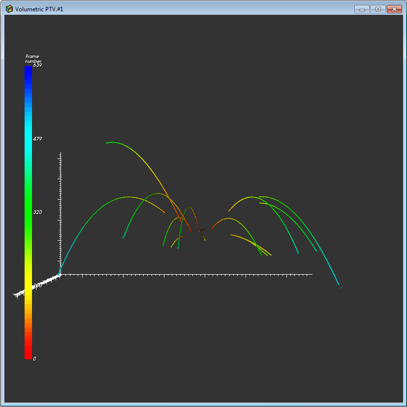
Measure of angle from XYZ positions
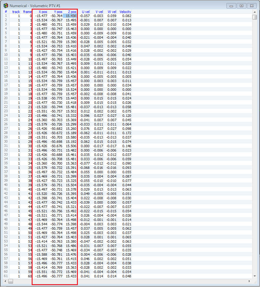
I made a 3D particle tracking image. It is (in this example) 17 tracks including the point of start in 0,0,0 (XYZ). Some of them didn't start the part of track (tracking problem), but it is not serious.
I also have a digital picture with any XYZ positions for each particle in the following frames. Now my question: is it possible in LabView to measure the initial angle (start) for each track of the first 10 frames (1-10)? On the photo above shows could be an angle for part of the beaches marked in red. There are only the initial angle, another part of the beaches is not bad actually.
Greetings to you.OK, it is not too difficult. You have a point P (I will choose 20, 34.5, 20), origin O (10, 10, 10) and you want to know the angle between the line of origin upside (call this OP line) and the line that is the projection of OP on the plan through the origin XZ.
Let's start with the passage of the origin 0, 0, 0. We do this simply by subtracting O p, which gives us a new point P' = 10, 24.5, 10. The point on the XZ plane is simply P' with its component is returned to zero, 10, 0, 10. Since our origin is (now) to (0, 0, 0), points P' and the projection of P' also represent vectors from the origin (that is, they are 'lines').
We now use the fact that the scalar product of two vectors is simply the product of the length of the two vectors times the cosine of the angle between them. I assume you know how to calculate a scalar product (if not, there is a function "Dot product" practical mathematics, algebra linear subpallet) and the length of a vector (vector Norm, even under Palette). The division, take the arc-cosine, and you should get (approximately) pi/3 (I took 24.5 = 10 * sqrt (6) I figured it would give me this angle).
If you write this as a Subvi with particle XYZ and XYZ origin (2-3 items 1-D tables) and Theta as output, you can put this inside a loop For that subscribe to all of the 2-D array of particles and the only original value and it will return an array of Angles.
I hope it's clear.
Bob Schor
-
The measure of Angle isnig DAQ 6009 phase
Hello
I am in a position two analog signals with the USB DAQ 6009, I wonder if someone has a tip,
or know any tool of angle measurement of phase of these signals using LabVIEW.Thank you
Ednaldo Cruz
Take a look at the iunformation of your unique extract VI found in treatment of signal-measures
Capture > 10 periods
Keep in mind that you have a multiplexed input, so you measure a certain delay in all cases.
(apply the same signal on both channels, for each sampling rate used, measure the phase, calculate the "group delay" for the correction)
-
Hello
I would like to create tiling Cairo-Pentagon.
Pentagonal paving of Cairo - Wikipedia, the free encyclopedia
Last year I had asked on triangle custom angle, gladly someone helped me but now I am facing a problem to create different polygons cranked up in illustrator. Of course it can be done manually, but I would like to create a lot of tilings as a reason for Cairo. For example, he has 5 faces and their angles are 120, 90,90,120,120.
A Script would be great that allows the filling of a box with these figures and creates these polygons.
Also last year CarlosCanto had helped me and its polygonal scenario was: (this script creates polygons with custom length and side numbers. What I need at this point is before custom angles. If it's hard to create number of sides in addition option, it would still be useful to have the script Pentagon with custom angles. Thank you for your help.
#target Illustrator
// script.name = polygonBySide.jsx;
// script.description = creates a polygone based on side length;
// script.required = an open document;
// script.parent = CarlosCanto; // 11/21/13;
// script.elegant = false;
// Shared via Creativetuts.com – Author : Carlos Canto
if (app.documents.length>0) polygonBySide ();
else alert (“no document to draw the polygon”);
function polygonBySide() {
var title = “Create Polygon by Side”;
var sideLen = Number(prompt (“Enter Side Length in Points”, 20, title));
var numberOfSides = Number(prompt (“Enter number of sides”, 5, title));
//var s = 2*r*Math.sin(Math.PI/n); // side length = 2*radius*sin(180 deg/number of sides)
var radius = sideLen/(2*Math.sin(Math.PI/numberOfSides));
var idoc = app.activeDocument;
var ctr = idoc.activeView.centerPoint;
dw = idoc.width;
dh = idoc.height;
wc= dw /2;
hc = dh *-0.5;
var ipoly = idoc.pathItems.polygon (ctr[0], ctr[1], radius, numberOfSides);
ipoly.position = Array(wc-(ipoly.width/2),hc+(ipoly.height/2));
}
something like this will draw the shape you want.
but it would be quite a task to allow the user to enter all angles, etc...
var L = 100;
var Sx = 100, Sy = -100, h = L/2, g = Math.sqrt(3)*h;
var points = {
    a : [Sx,Sy],
    b : [Sx+g,Sy+h],
    c : [Sx+g+g,Sy],
    d : [Sx+g+g-h,Sy-g],
    e : [Sx+h,Sy-g]
};

var doc = app.activeDocument;
var shape = doc.pathItems.add();
shape.setEntirePath(Array(points.a,points.b,points.c,points.d,points.e));
shape.closed = true;
shape.filled = false;
shape.stroked = true;
shape.strokeWidth = 1;
Here's a Visual of your form.
It can be broken down to still 4 triangles and a rectangle.
All triangles are 30-60-90, so the calculation is fairly simple.
Edit: Sorry, in the script I use 'h' and 'g' for the triangle not 'a' and 'b' as the diagram below.
In addition, point.a is the left most point and it works in a clockwise direction around the shape.

-
How to measure and mark the value of real-time data?
Hello
I need to measure and trace in time real RMS value of EMG power. I did a VI. But I don't know why it didn't work. Can someone help me please? My VI is set in 2013 and 2011 both version. An example of data is also attached. Thanks in advance.
Taslim. Reza says:
I tried RMS PtByPt VI. But it has not been wired because the source was table 1 d of double and double sink.
Well, ptbypt tools affect only one value at a time, so you must place them in a loop FOR. Here's how.
-
with an average of 100 consecutive measurements below a threshold value
Hello
I just started programming labview. I'm having difficulties with just this very simple programming code. I was breaking my head all night. I'd appreciate a quick response.
How can I make a code that would allow an average of 100 consecutive measurements which are below a certain threshold value in labview?
Thank you.
Try the joint. The key is shift registers-(blue) integer is a counter of deca thresholds measures and it returns 0 if there is a measure above threshold the result is saved whenever the counter is greater than 100 (indicating > = 100 consecutive values of 'good'). This also prevents internally while loop and outer loop causes the records to shift to reset. I added a function to "define the position of the file" then the values will be added rather than overwrite the file. You will probably need to insert a carriage return in the string that is written in the file so that the values appear on separate lines. I also changed your data types of DBL - they were I32 (integer) that doesn't seem to jive with your indication that you take analog action.
-
DAQmx HAVE bridge Measurements - first and second values electrical and physical
Hello
Can someone explain the significance of the 'first electric value' parameters 'first physical value', 'second electric value' and 'physical second value', when you set up the information of scaling for measurement of the Bridge (pressure or force)?
If I have a class scale 0 to 200 lbs with a sensitivity of 2mv/V and a voltage of 2.5V...
I thought that the settings should be:
Electric units = mVolts/Volt
1st electric value = 0
1st physical value = 0
2nd electric value = 5 (2 mV * 2.5 v = 5 mV)
2nd physical value = 200
But it seems that the 2nd electric value is supposed to actually to be the sensitivity of the sensor (in this case 2 mV).
Am I missing something here?
Hi ebloohm,
That is right. For your load cell excitation of the 2.5V will give you a rangle of 0-5 mV for output. You 0mV at 0 kg and 200 pounds, you will have 5 mV. The values in the table are used to scale readings of mV to lbs. The sensitivity of the sensor is already taken into consideration with the mV range values. If the cell has a sensitivity of 3 mV/V you instead would have 0 and 7.5 to your table. The good values in your original post.
-
Measure the silences (export values for the markers to Excel)
Hello!
I have the following task: I have wav files containing words listed by people. I need to measure latency between these vocalizations and export values in Excel.
I found a function of marking of phrases (Edition-> Auto-Mark). But there are 2 problems:
(1) I'll measure not gourmet, but latencies between them. There is a solution with subtraction of the time of the beginning of the next word at the end of the previous, but it's not very practical.
(2) in any case, I don't know how to copy these values I get when phrases daub. There is no possibility to copy them in the window of markers (see the attached screenshot), or export them in any case.
Help me, please! Thank you in advance.
Luckily for you, this has been a problem in the past - and bored one individual to create CueListTool, which is perfectly able to export the list of markers in Excel. Should be all you need; You can sort the silence of the noise outside the hearing quite easily with this, I think.
-
Can I get LabView fires on when a measure reaches a certain value?
1. I'm running an expirment in another room, and I'd like to be able to leave, then have it send me an email (or something, we'll just say run a .exe or comparable) so that I can know to go back and monitor the experience.
Are there features for which BT I've not seen? What in versions 8.6 or future?
2. I'm having serious crashes with my XP SP2 and LV 8.5.1, running a VI which loop continuously, although I think today that maybe I thought about it. It was perhaps because of my anti-virus, AVG Free software.
He knows stability problems with anti-virus software, or in the edition of XP in general? I get crashes between 20 minutes and a few hours in, but then just restart to fix it. I just uninstalled AVG Free (obviously not a permanent solution) and try without.
If you want your program to perform a specific action based on a measure, the simplest is to use the comparison functions. The entries are polymorphic, so you can wire a variety of types of data to an entry. You can then wire just the output of a case statement. You have e-mail on data Communication functions > protocols > SMTP e-mail palette.
-
Filtering measure based on a value from column to RPD
Hello
I created 2 measure in RPD effectively: channel change SLA
1 success Count who is count (Response_Event_DateTime) and
2. failure Count which is count (Failure_Reason_Key)
and in the report I put filters for these measures in Edit as formula
Success: FILTER ("ALS DONE change the channel". "County of success' using ("SLA MADE the channel change"". ")" ((Right key failed"< 1))
Chess: FILTER ("ALS DONE change the channel". "County of failure" using ("ALS FACT the channel change" ".") " ((FAILURE_REASON_KEY"NOT IN (-1, 1)))
then I calculated the percentage of success /(Successes+Failures) * 100
Everything works fine, but is there a way to put these filters for the successes and failures in RPD? So that users can simply drag and drop these measures and calculate the percentage of success?
Thanks in advance
SiriYes, you can put it in SPR... Simply create 2 new columns of logic more under table "Channel change ALS MAKES"
(1) success logic column
(2) failures logic columnFor success, check the box "use logic existing columns as source", then click 3 points...
And then in the expression builder... build the formula above... IE
FILTER ("ALS DONE change the channel". "County of success' using ("SLA MADE the channel change"". ")" Key failure of reason. "<>Even for outages logic column
Make two columns in the presentation layer, and then you're done...
Thank you
Ashish -
Hello friends
I need to measure the angle of rotation of the shaft with a precision of 1 degree... is there any simple device can I connect with usb 6008 custom angle...
Thank you
180 degrees is very different from continuous rotation. Just wire a potentiometer to one of the analog inputs and try to calibrate it.
You don't need the LM317. It will not help you with what you have described so far.
Lynn
-
Delay between angle and entered analog on a 6221
Hello
my test setup consists of a (8184 current run LabVIEW RT) embedded PXI controller which uses a PXI-6221 of data acquisition. One of the outputs analog of the 6221 creates a demand for speed that is sent to a servo controller. the servo drives then the test configuration. Between the servo and the remaining test configuration, a quadrature encoder is located. Both the 6221 meters are used to measure the position of the servo (using the trains of pulses A and B) as well as the speed of the servo (frequency of A pulse train). In addition to these counter inputs, some analog inputs of the 6221 serve as well to recored the configuration of test signals.
In this configuration, one of the analog signal has a frequency of n periods per revolution of servo (determined by the mechanical design of the test facility). But when I leave the servo turn to for example 100 rpm, then decelerate from status quo with a constant deceleration and then draw the analog signal against the measured angle, I see clearly that as long as the speed is telling, I n periods per turn (or a passage from my analog AC to zero each 1/2n towers); However, as soon as the slowdown begins, the plot gets stretched along the axis of the angle (so the plot tells me there are less than n analog periods per turn, which is impossible because it would require the mechanical destruction of the facility).
However, I can calculate a position based on speed information signal, as I got to the second counter (by integration of the speed). When I do this for the above velocity profile and draw the analog signal against the calculated angle, I see exactly n times / revolution, no matter how fast the installation program is rotating (just the expected behavior).So, apparently, the speed measured is "in phase" with analog signals, while the measured angle has a "phase error. Draw the angles measured and calculated against the time tells me the same thing: the measured angle is always late (compared to the calculated angle). The period is not constant throughout the measurement; I've seen values between 30 and 170 ms within a single record. Due to this change of variable, inserting a delay for all channels, but the angle is not a great idea.
Unfortunately, calculation of the position of the speed signal is no option for me, because the direction of rotation is changed during measurement; because speed information I have based simply on a frequency of pulse train, it contains no information management, therefore a calculated position would be unaware of the changes of direction.
Does anyone have an idea whence thios delay and what I can do to fix this problem?
Try a position different methods of decoding or exchanging the meter channels has not made a difference.Thank you!
Hey Kevin,
attached you will find the last block diagram (no new translation this time, since no changes have been made that require a), which includes your last suggestions (explicitly start the task of AI, remove the excess constraints) with a flat sequence structure that applies all the preparations of task to finish before the start of the first task (I know I could have achieved the same effect of intelligent routing of the signal error, but I think the code is) better readable this way).
Without OPI, LabVIEW tends to start to have, ao and tasks of the angle of the very different moments, which (for some reason that I don't understand - we have a sample clock based calendar here, and the sample clock is run, well after the three mentioned tasks...) tends to cause delays in the order of several 10-100 ms between tasks. With the structure, this problem is eliminated.
The Sub - VI just above DAQmx writing contains the "conduct" code that I used in the last screen shot to "serialize" the requested speeds - in this way, the table that contains the requirements of speed does not need to be rebuilt.
The code that creates a weather channel frequency implicitly timed measure left the VI shown here in a second VI that is running on the host computer, because everything that involves a calculation and does not require any intzeraction with the DAQ hardware is better placed there (the 850 MHz on the PXI controller celeton is slower than 2 definitiely something host GHz Dual-Core system).
The behavior you mentioned for the task "not started" HERE is what wrote using LabVIEW. I thought the block of relaxation that I had at the beginning would treat the start of the task - at least, the code like this figure repeatedly in the examples that come with LabVIEW.
I don't really understand what has caused the problems I've had - it seems that it was the combination of the measure quickly loop iteration with the start of task based on trigger HERE, but I do not understand what are the mechanisms in the background caused the problem (too forced loop was not the cause; the same block diagram works well with an additional loop timer).
If the solution was composed of the following steps:
-remove the old code calculating speed, replace it with a better code out of the main loop. This allows to
-reduce considerably the frequency of the main loop.
-Pull the DAQmx writing out of the loop, and
s ' ensure that all tasks are started explicitly just before the main loop starts to run.
-Possibly remove excess constraints of the main loop.
-
Sharing of Boolean values across while loops
I'm new to Labview and I try to use an angular encoder as a type of switch.
I want to take measures continuously from the angle of the encoder and turn on an analog output signal, each time comes in a certain angle. When the encoder drops from this angle, I need the signal to turn off.
To do this, I try to run two parallel while loops. We measure the angle of the encoder, while the latter creates the output signal. What I want to do is to put a logical statement in the measurement loop that will record 'true' if the maximum angle is reached. I try to get that 'real' statement in the loop of generation of signals as a trigger to turn on (using a case structure and the "DAQmx Start Task.vi") output. The question I have, is that the 'real' statement cannot exit the loop to measure up to the end of the loop. But since I'm running it continuously, the loop ends. Thank you.
Create a local variable of the Boolean in anxiety. Right-click on the local area and select change reading. Put this inside the loop else local. If you have a loop that writes to the Boolean value and a loop that reads from the local. Now you can remove the wire that comes from a single loop and feeds on the other. Then your curls will work in parallel (if there is no other dependencies of data between the two loops).
As an alternative to local variables, you can use a queue to transfer data from one loop to the other. A loop (the producer) will write to the queue. The other loop (consumer) reads from the queue. See the examples on the architecture of producer-consumer for more information.
-
measurement of continuous degrees
Hello
I have an arrow that revolves around constant point. I measure the angle of rotation of this arrow. When the arrow cross 90 degrees instead of 91 degrees East - 89, instead of 180 is 0. How to make a continuous measurement of 0 to 360 degrees?
THX
Here is a quick sketch. Most likely, you will have to tweak it a bit depending on how you set the angle.
(A lot of your code much easier...)

Maybe you are looking for
-
Windows error recovery, "load failed with error 1009 (STHIVE #0).
Hello world This problem occurred to me yesterday. When I started windows, there is here a dialog box saying "Windows Error Recovery" and below, is "Unable to start Windows. A recent hardware or software change might be the cause. "(I don't remember
-
Toshiba warranties - no value in Thailand
Hello Probably applies to many other countries and situations. If you thought that to have an international warranty would be useful on trips abroad and then think again. When in Thailand the only service center Bangkok - and guess what - they say th
-
HP elitebook 2540p password reset
Hello I bought a HP Elitebook 2540p, he arrived with a bios password is already set. Is it possible to reset the password of the bios that I need activate virtualization options before I can use the laptop to its destination. Thanks in advance for an
-
Can't download adobe reader, because a sliprt.dll file is missing.
Original title: I am running windows vista family premium snd is unable to download adobe reader, because a sliprt.dll file is missing... have tried all suggestions, but no luck... How can I install the missing file? Have tried windows helpdesk for a