measurement of parameters of voltage in TDS7404
Hi all
Use TDS7404 oscilloscope and via another PC via ethernet am controlling the scope. I installed the drivers from tktds7k. As I posted in the other very old thread (that's why it didn't get more attention, it seems!), am now able to measure some basic parameters like the amplitude, frequency, duty cycle, rise time, fall etc time. The problem of getting 99.00 e36 is resolved by adding the required time between write and read visa.
Now for high transitional measure and low voltage transition and high equilibrium State and stationary State low voltages, manually, it must adjust (move) the cursors in the scope and there is no option to measure the values directly as the other settings, I mentioned in the first paragraph. Can someone tell me how to automatically measure the transition and the State of equilibrium of tensions without addressing the oscilloscope controls (hopefully with the help of the drivers it's possible). Please guide me how to achieve this.
Thank you
Mathan
For future use:
(1) Initialize.vi
(1) cursor state.vi
(2) cursor mode.vi
(3) cursor type.vi
(4) cursor source.vi
(1) set the trigger Type.vi
(2) set trigger transition parameters.vi
(1) get the cursor parameters.vi
(1) Close.vi
Tags: NI Software
Similar Questions
-
Measurement of current and voltage USB-4065
I have an application where I need to measure the direct current and the voltage. The current and voltage will be stable if the measures do not need to be simultaneous. I would use a USB-4065 to the two measures. I've seen the kb indicating the voltage inputs must be disconnected when the measurement current. The current inputs must be separated for a measure of tension?
Hi Collin,
I think that you are referencing this knowledge base. After a few tests, and worked with the R & D group, it seems that the effects of input connections are perceived during the passage of two ways. When the current entries are connected, a less accurate voltage reading occurs. As such, please disconnect the current inputs for a measure of tension (as well as disconnect with tension when taking a measurement of current entries, who you know).
-
Measure the current and voltage using DMM sharing a port
I want to measure pressure several times on a pcb, where I connect the ports of digital multimeters to the card using simple cards. Switching between the different voltages is done using simple. If the black port of DMM (the second from the top photo) is connected to the Earth to give the measure correct volt.
And then I want to measure current through different lines. The problem is here. Given that two measurement types share a port, how do I get the correct voltage and current measurement? The second port of top would be grounded, so I can't use the method of measuring the voltage across the line through a resistance with a known value, since then the second port must not be connected to the ground. How can I use the current state of the DMM measurement? How measure current? Are there examples of this? Tried looking through manuals, but could not find the good starting points.
so I can't use the method of measuring the voltage across the line through a resistance with a known value, since then the second port must not be connected to the ground.
On all of my games to test I have to mux my land of the signal along with the salvation of my signals.
All my mux test sets are set up for the topology 2-wire because there is no other way to do it without the weak side of switch also.
-
How can I programmatically change the parameters of voltage range in a DAQ Assistant
Hello
First post here.
I need to be able to change the properties of voltage range of a daqmx assistant DAQ based on user input. My material, an SCXI module - 1102C does not change this property on a running task, so I would together the range of input voltage analog before activating the DAQ Assistant, or break the DAQ Assistant immediately after it starts, set the values, and then resume.
I don't know how to change the task ahead because the DAQ assistant creates the task when it is running, and there is no job before that.
In the attached photo, I have a conditional section, configured to run only if the loop iteration is 0. I take the task of the Daq assistant, sending him stop vi of task, set the property and then send the task with the snap the vi task. I can watch him run with lightweight debugging on, and everything seems to work properly, but on the second (and all others) iteration of the loop, I read I. Max and it seems that a re DAQ Assistant set it to the 5V. You can see what's going wrong here?
BTW, there is a continuous acquisition and the code doesn't produce error messages when executing.
I've encountered a similar question someone posted here in 2006, but his question was specifically a Labview API (VB, I think) and not a real solution of G.
Attached are the real vi in question and a PNG of the block diagram.
Thank you!
Ruby K
First of all, if you want to start getting beyond the basics with the DAQ hardware, you have to stop using the DAQ assistant and do it with lower level VI DAQmx. There are hundreds of examples in the finder of the example. You can even make a right-click on the DAQ assistant and select open front panel. This will create a Subvi, you can open and see what is happening behind the scenes. Do it. I think you will find that the task DAQ is recreated on each (although I'm not 100 percent the way parameters are established or maintained in each section of this sub - VI).
The second problem is that you have a bit of a race on iteration 0 condition. These two property DAQ nodes are running at the same time. Thus, when you read the AI. Max, this can happen before or after the AI. Max is located in the structure of your business.
Thirdly, make sure that involve you your son of the error.
-
I can measure analog USB supply voltage using Labview?
I'm basically feeding a (nominal) 5V USB power sensor, but the output of full scale depends on the real for a particular measure input voltage - what I want to do is to get labview to measure the voltage at the USB port at the same time it samples the voltage of the output sensor and then that of full scale output for that instant in time can be calculated and thus give a measure more accurate. Is this possible in labview? Thank you very much.
Haydn Barker
Makes a lot of sense, actually - probably would see a few mV dropped from the point of measurement of the sensor point... then you work with equations/remedies just to work with an inaccurate level anyway. Okay well I'll write that off as a bad idea then and just stick to the system, because it isn't now - I don't know that it will be enough. Thank you for your answers and help.
-
Measurement of current and voltage on Agilent B1505A
Hi all
I'm learning to program the Agilent b1505A using LabView. I want to just start with a simple measure of a voltage supply and reading/measure of the voltage and current.
I was able to analyze the data and apply tension without and the problem. However, I can't understand how to check the voltage and the current. I can get it only to record one or the other.
I don't know how to know everyone is with Flex Agilent controls. When we look through the manual, I see that there is a CMM order that sets the mode of operation of EMS measure. I put it in mode 4, which measures both, but it still does not work.
Anyone who is familiar with the use of LabView to parameter program Agilent analyzers?
I got my code and the manual of the order of Flex of Agilent.
Thank you.
I think I found my problem!
It is in the FMT command that specifies the format of data output.
Thank you.
-
Measures of true bipolar voltage with USB 6008/6009
The 6008 or 6009 to make true bipolar (positive and negative voltages referenced to GND) measurements? If not, what is the solution to purchase cheaper data this feature?
Thank you.
The question of unipolar vs bipolar vs bipolar Pseudo-aleatoire also was mentioned in this thread. The 6008 6009 use bipolar-only mode and load the setting differential input or CSR. Please note that {unipolar / bipolar / Pseudo-bipolaire} is independent of {differential / CSR / Pseudo-differentiel}.
The 6008/6009 don't use 'Pseudo-bipolaire', which means that each differential input should be positive with respect to the ground.
Best regards
-
Can SCXI 1102 measurement of current and voltage signals simultaneously?
This may be a simple question, but I have a pair of moisture sensors that output 3 x 0-10 Vac @ 10 my max of signals that will be connected to a test loop that will have also a pair of sensors of flow as 2 x 4-20 my output signals, and I need to know if I can connect all four sensors on the same card of SCXI 1102 with endings of 1300 block , or if I need separate maps for the voltage and current signals. I am also looking at extra material for the other sensors, so I can have a different card if it will do the job better.
Thanks in advance!
BBalmforth Hey!
If I understand your description of the system you want to measure tension through the moisture sensors and known for flow sensors simultaneously.
Absolutely, this can be done with the 1102. In the pilot DAQmx can we individually select the channels to read the voltage by the moisture sensors, and then choose the appropriate channels to read the current of the flow transducers.
Let us know if there is something else you need said.
Happy holidays!
-
How to change the parameters of voltage/mAh battery?
Hello
I bought a VGP-BPS9 (11, 1V / 4400mAh) for my laptop of SZ-670N who had a VGP-BPS10 (10.8V / 5800mAh) when I was abroad. The local Sony rep guy said that the original model was not available on the market and I have to use a similar stack
 and for this he needed change some settings (I guess that voltage and mAh) on my computer to make the new model works. Since then, most of the time, the battery LED starts flashing and alarms in Windows that I am out of battery while it is still physically full and I remove and re-connect the battery to make look it new!
Is it possible to return to the original values, so I can reuse my old battery and get rid of this frustrating situation?
Any useful comments will be appreciated

Hey rich! It's a VGN - SZ 670N.
-
Hello. I wrote two programs for the NOR cDAQ-9178 that work perfectly, but now I would like to combine... and users the ability to perform a measurement of the temperature (module NI 9214) or a measure of tension (NI 9201 module). I tried to use an Enum to a case Structure control, where the
user can choose either 'Measure the temperature', or 'Measure the tension', but during execution of the program, only the before user input panel opens and the program stops. Could someone please look at the code below and give me advice on the placement of my two programs in a structure of case? Each program contains two screws... a Subvi user input and a measure vi. Is it possible for me to drag the temperature and tension screw in the structure of matter? Thank you.
FYI - I am reposting this, because I couldn't get tethering to work on my previous post
I found my solution. I had to right click on the Subvi vi... 'Subvi node Setup' and select set the front panel
-
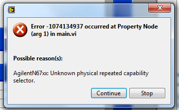
n6700 parameters of voltage/current query via the mode property
I try to back the tension of the query and the current settings on the power modules in my N7600 chassis. I use this routine. I get the following error. It works very well with my E363x feeds
It's working now. I had to add the 'active' channel to the node with the voltage and current demands. I got it that way originally, so I don't know why it didn't work. Maybe I still had the old broken driver... thought that I had a new already when I tried. It is in any case, everything works fine now. I can share what physical supply is used with MAX without the code never know the difference.
-
I have to be able to measure the peak voltage in an alternating signal Ridge. However, the frequency is 40 kHz, which is too high to measure using data acquisition (because the sampling frequency ira not very high). How can I measure the waveform using a multimeter, gpib? Is there a sample there code that will help me?
Thank you
BernoulliLizard,
In your original post, you said you wanted to measure peak to peak voltage of a 40 kHz signal.
I don't know all voltmeter that will do that.
Get an oscilloscope or a DAQ hardware with a high enough sampling rate. According to the bandwidth of the signal (not the same as the frequency of the signal), the PCI card for approximately $500 devices (US$) a variety of factors to form for $1500 or less must be able to do the job.
Lynn
-
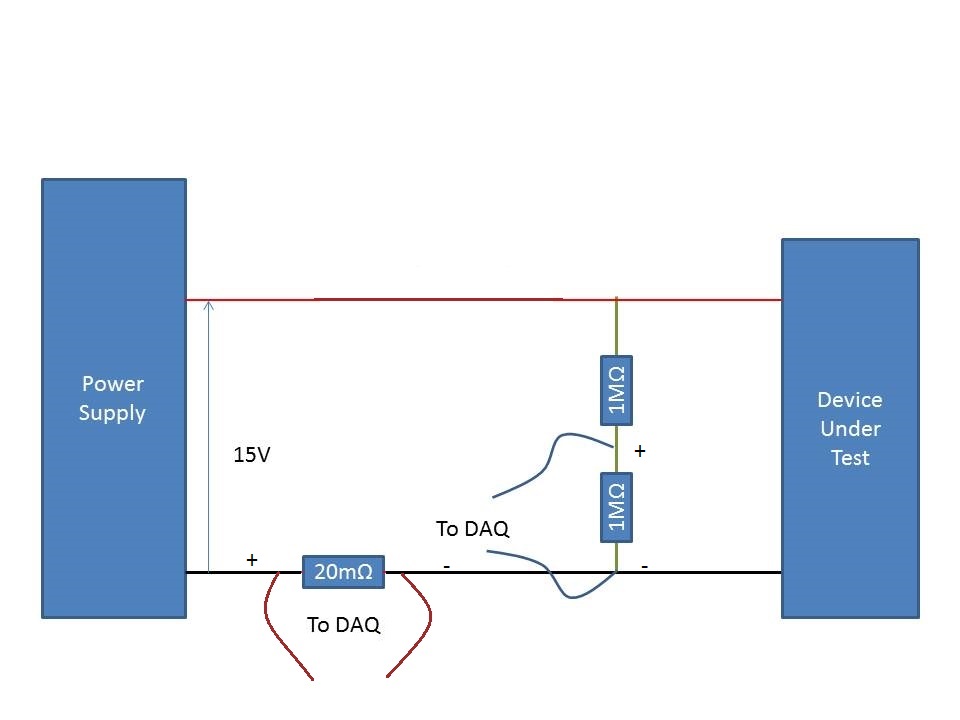
Measurement of the current rail voltage > 10V
Who am I to measure the current and voltage on a 15V supply rail. (Here's a copy of my circuit attatched) I use an acquisition of data USB-6225 and Lab View,
I have my camera to test connected to a power source. I connected two differential channels to the acquisition of data, one for the current and the other for the voltage.
I understand that data acquisition is unable to manage more than 10V so I use a voltage halfway through the voltage divider. When I run the action, the indicated current is incorrect. It shows the 10A when it should be about 500 my.
When I reduce the tension on the power supply 10V, it everything works fine, so I think that its got something to do with the limit of 10V.
Please can you advise how I can connect that places correctly?
Do it this way.
-
Hello people,
I've read several documents on the site OR about the premium over common measures of mode and I think I understand, but I'm looking for confirmation through two examples (please).
Both examples assume a data acquisition card OR with +/-10V inputs and a maximum operating voltage of + / 11V (e.g. PCI-6052 with programmable gain 0.5).
Example 1: Suppose a DC voltage with two resistors divider and a differential input on the daq card configuration. First resistance = 4 Ohms connected to 100VDC, second resistance = 96 - grounded (0) Ohms. This results in a decline of 4VDC to the terminals of the first resistance. However, I believe that the differential voltage of 4VDC may be connected directly to the daq card because the absolute voltage (i.e. common mode?) is in fact 96VDC to 100VDC which is outside the "working range' of + / 11V for the card. This conclusion is correct?
Example 2: Suppose a differential measure between two AC signals and a differential input on the daq card configuration. First report = 25v@0deg, second signal = 10v@180deg. Some documents on the Web site of NOR, I gathered that the common mode voltage is the average of the vector representation of the input signals. In this case, it would be (25v@0deg + 10v@180deg) / 2 = 7.5v@0deg. I think that this signal can be directly connected to the daq card because one of the signals (25v@0deg) is outside the range of the card work (even if the result "means vectors" is within the scope of the map daq. This conclusion is correct?
Thanks in advance for any help,
chassan
Chassan,
You're right both of your examples. Is the best way to look at that is that even if you take a measure differential the maximum voltage you can submit a single channel to the + / 11V to the 6052E. Hope this clears things up a little bit.
-
Measure the voltage and the temperature at the same time with a single card PCI 6014 DAQ?
Hello guys,.
I'm doing a charger measuring the voltage of the battery, the charge current and the temperature of the battery using a 6014 cardboard...
I want to use my PCI6014 DAQ card to measure 2-channel analog voltage input and 1 temperature Channel Analog input using thermocouple type k measurement of voltage or temperature isolation is OK, but I can't understand how to measure the voltage and the temperature at the same time... I want to use input differential...
Thank you in advance, all the tips
YSL
Create a task and add channels to the task, as follows:
Christian

Maybe you are looking for
-
Laptop: unable to connect to Internet via WiFi
I can't connect to the Internet when I'm on WiFi. What can I do? Bill
-
Memory for the Satellite 2400-103
My laptop satellite has 256 RAM, can I upgrade to 1 GB of Ram, or only 512?103-model Satellite S2400!A Finn
-
How to do a reset on 5 s screen unusable?
My phone was blue screening, you already have a replacement, but I need to erase all my info from my old phone. How can I do when I can't use the screen?
-
TouchSmart 23-h024 stand adjustment
Is the rear support on the adjustable Touchsmart? If so, how it unlock? It feels as if I could easily break.
-
HP Officejet Pro 8620 - won´t impression of MS Office
Hello my printer HP Officejet Pro 8620 prints from Chrome, Adobe reader, but won´t impression of MS Word, Excel... I tried it on 3 laptops. Windows 7 - Office 2003 Windows 8 - Office 2007 8.1 - 2013 Office Windows (x 64) Scanning is ok. The printer i