Measurement of current and voltage USB-4065
I have an application where I need to measure the direct current and the voltage. The current and voltage will be stable if the measures do not need to be simultaneous. I would use a USB-4065 to the two measures. I've seen the kb indicating the voltage inputs must be disconnected when the measurement current. The current inputs must be separated for a measure of tension?
Hi Collin,
I think that you are referencing this knowledge base. After a few tests, and worked with the R & D group, it seems that the effects of input connections are perceived during the passage of two ways. When the current entries are connected, a less accurate voltage reading occurs. As such, please disconnect the current inputs for a measure of tension (as well as disconnect with tension when taking a measurement of current entries, who you know).
Tags: NI Products
Similar Questions
-
Measure the current and voltage using DMM sharing a port
I want to measure pressure several times on a pcb, where I connect the ports of digital multimeters to the card using simple cards. Switching between the different voltages is done using simple. If the black port of DMM (the second from the top photo) is connected to the Earth to give the measure correct volt.
And then I want to measure current through different lines. The problem is here. Given that two measurement types share a port, how do I get the correct voltage and current measurement? The second port of top would be grounded, so I can't use the method of measuring the voltage across the line through a resistance with a known value, since then the second port must not be connected to the ground. How can I use the current state of the DMM measurement? How measure current? Are there examples of this? Tried looking through manuals, but could not find the good starting points.
so I can't use the method of measuring the voltage across the line through a resistance with a known value, since then the second port must not be connected to the ground.
On all of my games to test I have to mux my land of the signal along with the salvation of my signals.
All my mux test sets are set up for the topology 2-wire because there is no other way to do it without the weak side of switch also.
-
Measurement of current and voltage on Agilent B1505A
Hi all
I'm learning to program the Agilent b1505A using LabView. I want to just start with a simple measure of a voltage supply and reading/measure of the voltage and current.
I was able to analyze the data and apply tension without and the problem. However, I can't understand how to check the voltage and the current. I can get it only to record one or the other.
I don't know how to know everyone is with Flex Agilent controls. When we look through the manual, I see that there is a CMM order that sets the mode of operation of EMS measure. I put it in mode 4, which measures both, but it still does not work.
Anyone who is familiar with the use of LabView to parameter program Agilent analyzers?
I got my code and the manual of the order of Flex of Agilent.
Thank you.
I think I found my problem!
It is in the FMT command that specifies the format of data output.
Thank you.
-
Can SCXI 1102 measurement of current and voltage signals simultaneously?
This may be a simple question, but I have a pair of moisture sensors that output 3 x 0-10 Vac @ 10 my max of signals that will be connected to a test loop that will have also a pair of sensors of flow as 2 x 4-20 my output signals, and I need to know if I can connect all four sensors on the same card of SCXI 1102 with endings of 1300 block , or if I need separate maps for the voltage and current signals. I am also looking at extra material for the other sensors, so I can have a different card if it will do the job better.
Thanks in advance!
BBalmforth Hey!
If I understand your description of the system you want to measure tension through the moisture sensors and known for flow sensors simultaneously.
Absolutely, this can be done with the 1102. In the pilot DAQmx can we individually select the channels to read the voltage by the moisture sensors, and then choose the appropriate channels to read the current of the flow transducers.
Let us know if there is something else you need said.
Happy holidays!
-
NEITHER 9207 reading current and voltage at the same time channels
I have a cDAQ-9178 chassis USB-three cards NI 9217 RTD, three cards 9263 0 - 10V and one the output OR 9207 16 channels analog card. What I m trying with this kind of things, is to read all the analog input channels (information of transducer, temperature, pressure, etc.) and adjust my controls to process with the analog output channels.
My problem at the moment is the following:
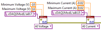
When I create tasks with DAQmx VI:s, how to create a task that reads current and voltage on the 9207 channels at the same time?
When I created a task for RTD-channels (16), a task for the outputs analog 0 - 10V (12), a task for the analog input 4-20mA (8) and a single task analog 0 - 10V input (8) I get an error-50103. I think it s because the tasks of current entry and voltagge are trying to use the same CAD at the same time and LabVIEW informs that "The specified resource is reserved. Tasks are to leave so that the analog output task starts first, then I merged all clusters of the error and the rest of the task are started by an order to current input-> input-> RTD input voltage. I get this error after the current enter task started and enter voltage task begins.
Because I m new on the LabVIEW and stuck in that time, I wanted to try the forum to find answers. I tried to find if someone else was having the same kind of problem, but with a quick search, there was none. I m in a bit of hurry, so I apologize if West a subject with a happy for that and I missed too much according to me.
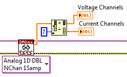
Really, the best way to do it is just adding 8 channels of voltage at a task, then 8-channel current, somewhat like this:
Then spread over different channels when you read later:
It should run without error. It always is multiplexed to sampling, but it will be much faster to create two separate tasks. There will be between 2ms (mode high speed) and 52ms (mode high resolution) between each playback channels, but it will still be much faster than the permutation of the tasks.
-
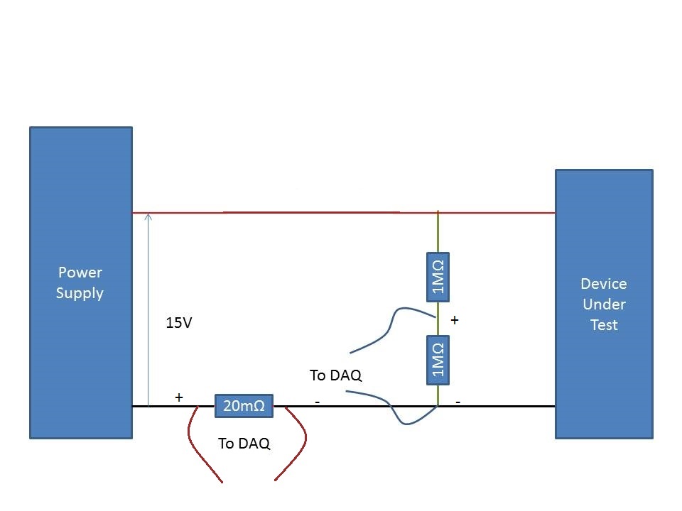
Measurement of the current rail voltage > 10V
Who am I to measure the current and voltage on a 15V supply rail. (Here's a copy of my circuit attatched) I use an acquisition of data USB-6225 and Lab View,
I have my camera to test connected to a power source. I connected two differential channels to the acquisition of data, one for the current and the other for the voltage.
I understand that data acquisition is unable to manage more than 10V so I use a voltage halfway through the voltage divider. When I run the action, the indicated current is incorrect. It shows the 10A when it should be about 500 my.
When I reduce the tension on the power supply 10V, it everything works fine, so I think that its got something to do with the limit of 10V.
Please can you advise how I can connect that places correctly?
Do it this way.
-
Currently, I am trying to log readings of DC voltage with an AA battery in an ASCII using LabVIEW 2009 of SingalExpress file and the USB-4065 digital multimeter (DMM). I have two stages:
(1) acquisition of Signal > voltage DC using DMM
-resolution 4.5 with 3.333333E the value-5 sampling period
2) save in ASCII
-The value to add to the file, delete the file after each race
Faster reading, I can get is a data point written in the ASCII file every eighth of a second.
Furthermore, I am new and software OR LabVIEW, the LabVIEW SignalExpress software I have is only for evaluation as it was included in the CD of the driver for the USB 4065 DMM.
- Max (30 000 samples per second) sampling rate is only achievable by a LabVIEW VI?
- Don't I have the wrong settings for DMM step?
- Is it because I haven't activated SignalExpress and am only using the evaluation version?
Thanks in advance for any help!

Hello Lukos,
You are assuming that you need access to lower level functions in order to obtain the higher sampling rates. In order to get these speeds, we need to disable some settings that are not accessible via Signal Express. You can create a VI and then use a step VI call in Signal Express to stay in the same environment.
Kind regards
-Travis E
-
Need help with measurement excitation current OR 9219 Module
Hello
I have problems to find the answer to my question. My question is... How do you analyze the excitation of a 9219 module current? It seems that the excitation current which is specified (0.0005 (A) is not what is provided at the exit. With a load of KOhm 10.5 a 0.00025 current is output. As the resistance changes as the current and measured excitation voltage seems to change. I just need to know the resistance... So, if I can monitor the voltage and current I can calculate the resistace. BTW, why don't the current excitement remains fixed in the first place?
Thank you
Nate
Hi Nate-
In almost all modes of the 9219, the current and the voltage automatically adjusts to the load it experiences. The resistance is then measured according to the amount of current and voltage sunk by the load. This is explained in 9219 User Guide and specifications. The guide also States the the 9219 input impedance according to which mode it is.
I hope this helps. Good luck with your application!
-
I/o current or voltage check with the switching matrix
Hi all
I want to use a switching matrix to test current and voltage of a control cabinet. For this, I have a voltage of the injector, injector current, a voltage measurement and measurement of currents from one side of the matrix (side line) and a 20 lines by I / O test. Is there a way to check (with a hardware or software solution) that we are ready for a test voltage or current in automatic mode.
The ideal would be to have a physical key indicating that we are testing the right card, but if the operator uses the wrong card, I would check it is not injected + 24V-on entry to an entry card 0-20mA current.I wish you turns me on!
Best regards
Vincent
Vincent,
Some approaches for you to consider:
1 Add a resistor or a few resistors to each card. Measure the resistance before applying all power to the i/o lines. The code of the resistance (s) to identify the class of Council (current or voltage) and rank (if applicable). Simple jumper on the unused pins of the connector can also be used.
2 measure the input impedance (or at least the resistive component) before turning the power on. An input voltage device probably has a high input impedance while the current input device has a low input impedance. It could detect and reject some devices with resistance to entry incorrect installed.
3. use a camera to determine which device is connected. (This should satisfy your request to be informed!)
4. you can replace the operator with a robot, but the robot would still need to use something like 1, 2 or 3 to identify the boards.
5. use edge configurations physically incompatible connectors/card so that the cannobe Board connected to the tester bad.
Lynn
-
measurement of current with usb-6009
Hi, my name is hung and I am a student in electrical engineering... I'm doing a thesis that the project using Labview and acquisition of data NOR UBS-6009 to simulate the function generator, Oscilloscope, Digital Microsoft (DMM)... and now I'm simulating DMM. I managed to measure the voltage and resistance which i use voltage divider method, but I encountered a problem with the current measurement. The problem is the USB-6009 to measure use the current, it measures an incorrect value. I tried to use the current CQI 0-20mA Sample.vi example but it always measures an incorrect value. If NI USB-6009 supports for the measuring current? Is there a way to measure the currents using USB-6009? Please, help me. This thesis project is so important for me. Thank you.
Hung,
Since you are a student in electrical engineering, I'll show you how to know the answers to your questions.
1. review the specifications for the USB-6009 case. In particular look at the specifications of analog input.
2. How would you measure current if you had only a voltmeter? Use the same method with the USB-6009 case. (Tip: apply the Ohm's law).
General comment: when using any measuring instrument, always consider maximum permitted values at the entrances so that the instrument is not damaged
and the measure is accurate.
Let us know how you do.
Lynn
-
Hi, I'm working on a project where there partly to measure resistance values in different parts of the circuit. Now, the company where I work currently at wants to get the NI USB-4065 USB. I use visual studio 2005 c# to develop applications and I need to know if I needed measurement studio or are there drivers (dll) just to get the values of resistance and General measures of circuit. I have need the controls or anything, just to programatically read the NI USB-4065 USB key values when I need the application.
Any help would be appreciated. Thank you.
Yes, you can have several NI 4065 DMM in your system. When you use the API OR-DMM, you open the handles separately for each DMM by using its name. His name can be configured inside the measurement and Automation Explorer (MAX).
In addition, you can go ahead and install OR DMM today. It is downloadable for free on ni.com. NOR-DMM (and most of the pilots NOR) supports the simulation. You go to MAX and create your simulated three 4065 s. Then you can start writing your program now. Since these devices are simulated, they will not return the real tensions (obviously) and that it won't react realistic hardware triggers if you use (obviously), but they are pretty close to the real deal to allow you to write a lot of code and become familiar with the API. No need to wait until you get the material - you can be really ready for it by using the simulation.
-
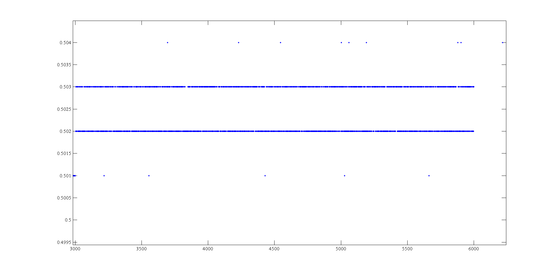
Measurement of voltage USB 6008 ranging from 1mV
Hi, I'm doing a supply at an angle for an amplifier using the USB-6008. The ranges I look are - 0.5 to 0.5 V and 0.5 to 2.5 V. To generate negative tensions, I use the + 2, 5V for a reading of differential voltage output as a 'ground '. Voltage measures have a delay that varies with the voltage, given this by drawing these variations and set the output to data acquisition there is still a 'noise' of +/-1 mv so that it is clear from this parcel of tension against the sample number:
It seems that at some point the values are being rounded up to the nearest millivolt. I need to get to a resolution of 0.5 mV for my device, it will be possible with the USB-6008?
The AO USB-600 x has a range from 0 to + 5 V and the 12-bit resolution. 5/4096 = 1.22 mV. Absolute precision is 7 mV typical and 36.4 mV maximum full scale. The noise of the AO is not specified.
If you measure the results with THE USB-6008, you have at least 0.5 mV, similar resolution system noise and absolute accuracy of 2.5 mV or more.
It's probably as good as you will get with the box USB-6008.
Lynn
-
Measures of current between 4071 and 2575 sometimes not correct
I use mode of handshake with a PXI-4071 scan list and an SMU-2575.
The DMM is current and the MUX is in mode 1 x 196.
When running the scan list, I have rarely (randomly) get a very small extent to the nA au (when to 4-20 MA). I'll run the scan list again and that the channel will be correct, so it seems not to match a channel.
I tried to increase the time of settling of the DMM and the MUX, but have had no effect.Any help would be great.
Thank you
Caleb Swieson
After further tests, we determined that it was indeed the devices to measure who pulled out the very low currents. So it wasn't the fault of the hardware. Oops
-
Measurement of angular position with encoder in quadrature and NI USB 6281
Hello.I have an application developed with labVIEW 7.1 and 6014 OR for the measurement of angular position using encoder quadrature, where are used 3 sons - one of them connected to the source, second to the OID (0 or 1) and a third to digital ground. I can't use the same application or NI USB 6281.Now connections, I would like to know how I can create a similar application in labview 2009 and how to make the relevant connections for NI USB-6281, which is a mx NI DAQ device. Please suggest. Thank you.
I have my loan application. I understand there are big difference using LabVIEW 2009 and NI USB card, compared to the previous version I was using THE LabVIEW 7.1 and a traditional daq. The difference, I should say that wellness is both in terms of simplification of code and the accuracy of the result. I was a little surprised, showing results. Thanks a lot to JB for your time and sharing those pieces of details.
I can well after awhile my code in the forum. Hope this helps someone like me looking for a similar application.
-
Current output digital USB-6009
Hi, I'm trying to increase the voltage output digital device USB-6009. I read a few topics on the use of a relay, but I couldn't get it.
I was thinking of using power 5V on the map because there current 200mA on it, but when I use it with open-collector output, it cannot change the relay. When I measure the current between
5V and ground: 200 ma,
5V output, I read a value around 30-40 my.
Why can I not use this 200mA with output? It is the Relay that I use.
If this is not possible, can I use an external power supply 5V (with more current) and a digital output to pass the baton without damage the 6009?
Outputs digital of the USB-6009 confined to 8.5 my. Your relay coli requires much more than that. Even if the power source can provide enough current for the relay, digital output can not put.
The solution is to use a buffer of extermal. The ULN2003 can switch currents up to 500 my and voltage up to 50 V while being controlled by digital output.
Lynn
Maybe you are looking for
-
I can get 10 in my Hp Media Center m8020n PC windows have Vista
I don't know what to do about 10 Windows for my HP Media Center m8020n. I've had this for about 8 years and he loves and does not wish to continue with it. Can I put Windows 10 here and update all software there need or do I have to buy a new PC
-
How to order the new AC for Satellite A350-20 q power?
Hello I bought my satellite A350-20 q 2 1 / 2 years and when I turned on my laptop screen was low, the power supply is already on, but he did not have any change. How can I order a replacement? Thank you
-
Hi, I used the troubleshooter of lenovo to solve a problem and 1 thing he showed, is that in Device Manager position sensor was not working properly can not load the driver, I uninstalled by using the Device Manager as I was advised that on next boot
-
LaserJet P1102W: Printer has stopped working
I've had my printer for over a year and never had a problem. A few days ago the printer stopped working. I tried to print and it would not allow me. He wanted to come to save the document, instead of giving me the privilege to print the page. I t
-
How to automatically store scans on a USB flash drive
How can I change the default destination for the scans in Windows 7 Fax & Scan go somewhere other than my C:\. I want all scans go to a USB flash drive and NEVER written on the C:\ drive at all, but can not find a way to do it.