Measurement of current and voltage on Agilent B1505A
Hi all
I'm learning to program the Agilent b1505A using LabView. I want to just start with a simple measure of a voltage supply and reading/measure of the voltage and current.
I was able to analyze the data and apply tension without and the problem. However, I can't understand how to check the voltage and the current. I can get it only to record one or the other.
I don't know how to know everyone is with Flex Agilent controls. When we look through the manual, I see that there is a CMM order that sets the mode of operation of EMS measure. I put it in mode 4, which measures both, but it still does not work.
Anyone who is familiar with the use of LabView to parameter program Agilent analyzers?
I got my code and the manual of the order of Flex of Agilent.
Thank you.
I think I found my problem!
It is in the FMT command that specifies the format of data output.
Thank you.
Tags: NI Software
Similar Questions
-
Measurement of current and voltage USB-4065
I have an application where I need to measure the direct current and the voltage. The current and voltage will be stable if the measures do not need to be simultaneous. I would use a USB-4065 to the two measures. I've seen the kb indicating the voltage inputs must be disconnected when the measurement current. The current inputs must be separated for a measure of tension?
Hi Collin,
I think that you are referencing this knowledge base. After a few tests, and worked with the R & D group, it seems that the effects of input connections are perceived during the passage of two ways. When the current entries are connected, a less accurate voltage reading occurs. As such, please disconnect the current inputs for a measure of tension (as well as disconnect with tension when taking a measurement of current entries, who you know).
-
Measure the current and voltage using DMM sharing a port
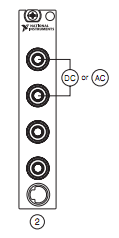
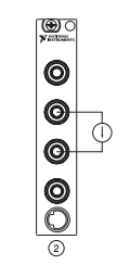
I want to measure pressure several times on a pcb, where I connect the ports of digital multimeters to the card using simple cards. Switching between the different voltages is done using simple. If the black port of DMM (the second from the top photo) is connected to the Earth to give the measure correct volt.
And then I want to measure current through different lines. The problem is here. Given that two measurement types share a port, how do I get the correct voltage and current measurement? The second port of top would be grounded, so I can't use the method of measuring the voltage across the line through a resistance with a known value, since then the second port must not be connected to the ground. How can I use the current state of the DMM measurement? How measure current? Are there examples of this? Tried looking through manuals, but could not find the good starting points.
so I can't use the method of measuring the voltage across the line through a resistance with a known value, since then the second port must not be connected to the ground.
On all of my games to test I have to mux my land of the signal along with the salvation of my signals.
All my mux test sets are set up for the topology 2-wire because there is no other way to do it without the weak side of switch also.
-
Can SCXI 1102 measurement of current and voltage signals simultaneously?
This may be a simple question, but I have a pair of moisture sensors that output 3 x 0-10 Vac @ 10 my max of signals that will be connected to a test loop that will have also a pair of sensors of flow as 2 x 4-20 my output signals, and I need to know if I can connect all four sensors on the same card of SCXI 1102 with endings of 1300 block , or if I need separate maps for the voltage and current signals. I am also looking at extra material for the other sensors, so I can have a different card if it will do the job better.
Thanks in advance!
BBalmforth Hey!
If I understand your description of the system you want to measure tension through the moisture sensors and known for flow sensors simultaneously.
Absolutely, this can be done with the 1102. In the pilot DAQmx can we individually select the channels to read the voltage by the moisture sensors, and then choose the appropriate channels to read the current of the flow transducers.
Let us know if there is something else you need said.
Happy holidays!
-
NEITHER 9207 reading current and voltage at the same time channels
I have a cDAQ-9178 chassis USB-three cards NI 9217 RTD, three cards 9263 0 - 10V and one the output OR 9207 16 channels analog card. What I m trying with this kind of things, is to read all the analog input channels (information of transducer, temperature, pressure, etc.) and adjust my controls to process with the analog output channels.
My problem at the moment is the following:
When I create tasks with DAQmx VI:s, how to create a task that reads current and voltage on the 9207 channels at the same time?
When I created a task for RTD-channels (16), a task for the outputs analog 0 - 10V (12), a task for the analog input 4-20mA (8) and a single task analog 0 - 10V input (8) I get an error-50103. I think it s because the tasks of current entry and voltagge are trying to use the same CAD at the same time and LabVIEW informs that "The specified resource is reserved. Tasks are to leave so that the analog output task starts first, then I merged all clusters of the error and the rest of the task are started by an order to current input-> input-> RTD input voltage. I get this error after the current enter task started and enter voltage task begins.
Because I m new on the LabVIEW and stuck in that time, I wanted to try the forum to find answers. I tried to find if someone else was having the same kind of problem, but with a quick search, there was none. I m in a bit of hurry, so I apologize if West a subject with a happy for that and I missed too much according to me.
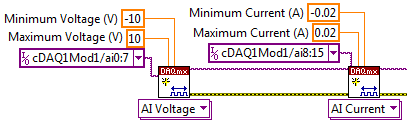
Really, the best way to do it is just adding 8 channels of voltage at a task, then 8-channel current, somewhat like this:
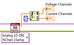
Then spread over different channels when you read later:
It should run without error. It always is multiplexed to sampling, but it will be much faster to create two separate tasks. There will be between 2ms (mode high speed) and 52ms (mode high resolution) between each playback channels, but it will still be much faster than the permutation of the tasks.
-
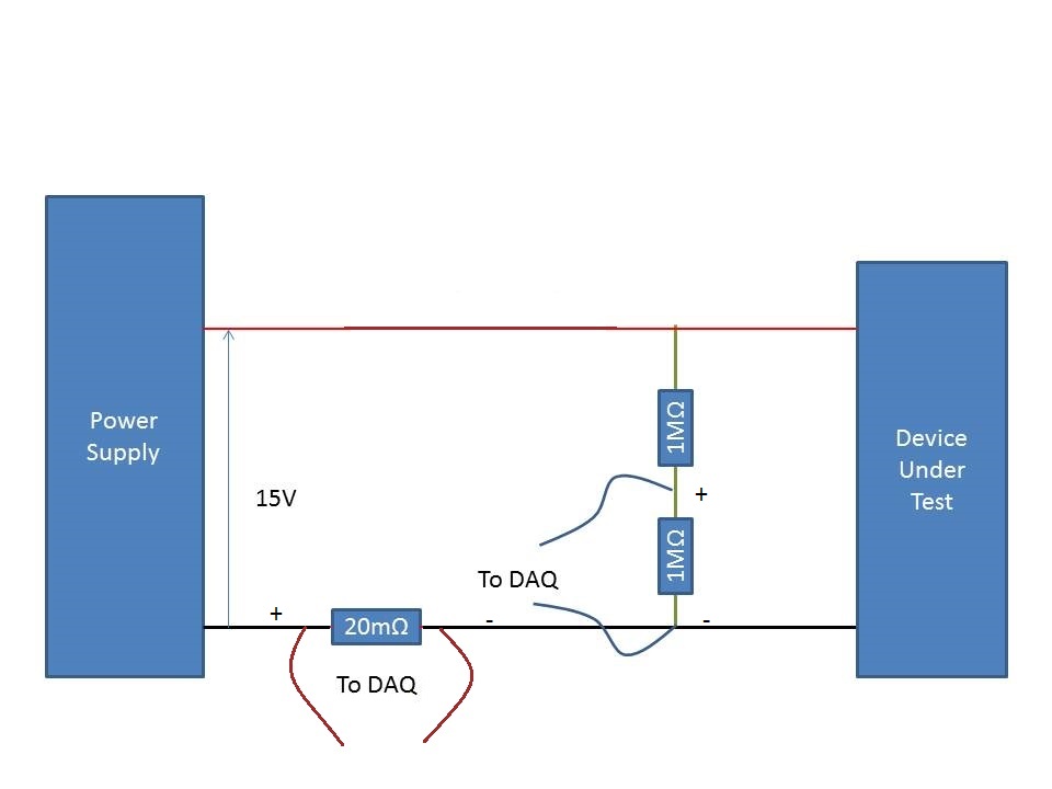
Measurement of the current rail voltage > 10V
Who am I to measure the current and voltage on a 15V supply rail. (Here's a copy of my circuit attatched) I use an acquisition of data USB-6225 and Lab View,
I have my camera to test connected to a power source. I connected two differential channels to the acquisition of data, one for the current and the other for the voltage.
I understand that data acquisition is unable to manage more than 10V so I use a voltage halfway through the voltage divider. When I run the action, the indicated current is incorrect. It shows the 10A when it should be about 500 my.
When I reduce the tension on the power supply 10V, it everything works fine, so I think that its got something to do with the limit of 10V.
Please can you advise how I can connect that places correctly?
Do it this way.
-
Need help with measurement excitation current OR 9219 Module
Hello
I have problems to find the answer to my question. My question is... How do you analyze the excitation of a 9219 module current? It seems that the excitation current which is specified (0.0005 (A) is not what is provided at the exit. With a load of KOhm 10.5 a 0.00025 current is output. As the resistance changes as the current and measured excitation voltage seems to change. I just need to know the resistance... So, if I can monitor the voltage and current I can calculate the resistace. BTW, why don't the current excitement remains fixed in the first place?
Thank you
Nate
Hi Nate-
In almost all modes of the 9219, the current and the voltage automatically adjusts to the load it experiences. The resistance is then measured according to the amount of current and voltage sunk by the load. This is explained in 9219 User Guide and specifications. The guide also States the the 9219 input impedance according to which mode it is.
I hope this helps. Good luck with your application!
-
I/o current or voltage check with the switching matrix
Hi all
I want to use a switching matrix to test current and voltage of a control cabinet. For this, I have a voltage of the injector, injector current, a voltage measurement and measurement of currents from one side of the matrix (side line) and a 20 lines by I / O test. Is there a way to check (with a hardware or software solution) that we are ready for a test voltage or current in automatic mode.
The ideal would be to have a physical key indicating that we are testing the right card, but if the operator uses the wrong card, I would check it is not injected + 24V-on entry to an entry card 0-20mA current.I wish you turns me on!
Best regards
Vincent
Vincent,
Some approaches for you to consider:
1 Add a resistor or a few resistors to each card. Measure the resistance before applying all power to the i/o lines. The code of the resistance (s) to identify the class of Council (current or voltage) and rank (if applicable). Simple jumper on the unused pins of the connector can also be used.
2 measure the input impedance (or at least the resistive component) before turning the power on. An input voltage device probably has a high input impedance while the current input device has a low input impedance. It could detect and reject some devices with resistance to entry incorrect installed.
3. use a camera to determine which device is connected. (This should satisfy your request to be informed!)
4. you can replace the operator with a robot, but the robot would still need to use something like 1, 2 or 3 to identify the boards.
5. use edge configurations physically incompatible connectors/card so that the cannobe Board connected to the tester bad.
Lynn
-
Measures of current between 4071 and 2575 sometimes not correct
I use mode of handshake with a PXI-4071 scan list and an SMU-2575.
The DMM is current and the MUX is in mode 1 x 196.
When running the scan list, I have rarely (randomly) get a very small extent to the nA au (when to 4-20 MA). I'll run the scan list again and that the channel will be correct, so it seems not to match a channel.
I tried to increase the time of settling of the DMM and the MUX, but have had no effect.Any help would be great.
Thank you
Caleb Swieson
After further tests, we determined that it was indeed the devices to measure who pulled out the very low currents. So it wasn't the fault of the hardware. Oops
-
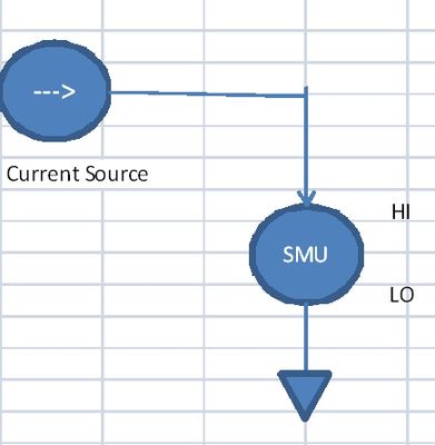
SMU, used for the measurement of current
Hello
I need to measure current in the range 5 to exit 10uA by a current source PIN. I would have usually connected PXI4065 on this PIN and measured current. But in this case the current to be measured is low.
I have EMS 4130, which has high accuracy of current measurement to 200mA range (0.03%+0.02)uA.
Can I use the current part of the EMS (CH1) measurement to measure current? What should I activate CV outputs (Hi = 0V) who appears in the soft front panel?
Or just without activating the outputs I can measure the current sink. The program of flexible panel displays current measurements, but I don't know if the EMS can be used like that.
Thank you
Not sure NI SMEs, as I have not had the chance to use it yet. SMU of Agilent could be used this way, so I guess with OR as well. You must use out SMU in constant voltage source / I measure mode. Would you say the SMU to hold the voltage at 0V, and allow current to the sink (or source) as necessary to maintain this 0V output.
-
measurement of current with usb-6009
Hi, my name is hung and I am a student in electrical engineering... I'm doing a thesis that the project using Labview and acquisition of data NOR UBS-6009 to simulate the function generator, Oscilloscope, Digital Microsoft (DMM)... and now I'm simulating DMM. I managed to measure the voltage and resistance which i use voltage divider method, but I encountered a problem with the current measurement. The problem is the USB-6009 to measure use the current, it measures an incorrect value. I tried to use the current CQI 0-20mA Sample.vi example but it always measures an incorrect value. If NI USB-6009 supports for the measuring current? Is there a way to measure the currents using USB-6009? Please, help me. This thesis project is so important for me. Thank you.
Hung,
Since you are a student in electrical engineering, I'll show you how to know the answers to your questions.
1. review the specifications for the USB-6009 case. In particular look at the specifications of analog input.
2. How would you measure current if you had only a voltmeter? Use the same method with the USB-6009 case. (Tip: apply the Ohm's law).
General comment: when using any measuring instrument, always consider maximum permitted values at the entrances so that the instrument is not damaged
and the measure is accurate.
Let us know how you do.
Lynn
-
Measurement of current with NI6250
Hello
I use the 6250 OR for certain analyses of analog input. In addition, I want to measure the current that I supply to the unit under test. The current is about 300 my.
I thought to use a shunt at 2 ohms resistance, so lowering the supply voltage of 0.6V and not having not too low-voltage measures. I intend to adjust the votage of 9.6 V power supply to get 9V after the shunt resistance, because I'm supposed to provide.
1. any comments or better suggestions for this?
2. I will calculate the current by measuring the voltage on the resistance. The question is I will use 2 unique inputs or differential input?
3 you are looking for in table 4-3, page 4-12 of the M Series DAQ - user manual, I see an application of a differential input voltage. There, they put 2 pull down of the resistance to Earth. I do as well? Can't I just apply the 2 lines of resistance, directly at the entrance of diff?
4. am I suppose to connect the ALWAYS to my power supply GND?
Thank you
Rafi
In your case, the differential is the way to go. You don't need resistance more bias from (drop) current if your PS is connected to (A) MASS somewhere anyway.
-
Move the engine and perform a measurement (thorlabs motors and drivers)
Hello world
I was just born in this world of Labview and I m quite lost. I´ll explain my situation:
Queue BEFORE the start of the measurement time is something that you must do it manually because it is up to the user.
Until how long to wait for the measurement of complete, the manual includes many examples of the use of registers and implements buffer to find out when the measurement is finished using a linear scan (this is how I do it). The idea is to set buffer equal number of datapoints (say 100 on your beach IV), ask what to measure (current, voltage, both) and the records to see when the buffer is full (say all 100 to 500 ms) election. Let the keithley 2400 settle tensions for you on the specified range and returns the set of data, once completed.
As far as when the movement is finished, you will have to see if there is a way to detect that your equipment (stick otherwise with the late pre programmed). If they are lit IV measures, you could do the following. The ABSENCE of any power source and measure the current. Check periodically after the movement commands are sent. Once you measure a current, the CDC for the cell, you must contact.
For data storage, use the shift on the state machine itself registers. Erase the registry when starting an analysis, then insert each measure if it is taken (table 2D or array of clusters). Another possibility is to use another while loop to back up data (a consumer) with the data being past in a queue and added to the file after each scan (this will help if you are concerned about breakage resulting from data loss). After each measurement, queue the data to a queue managed by the consumer. (you will need to keep track of which file to add data to).
-
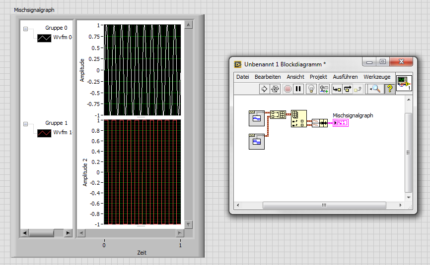
How to trace the temperature and voltage using the graph of Mixed Signal
Hello
I use the NOR cDAQ-9178, module NI 9214 (temperature) and the module NI 9201 (voltage). My program allows the user to choose among 3 different tasks, Masurement of temperature, voltage, or both. When you select the task for temperature and voltage measurement, I was drawing all channels on the same graph. I was invited to separate channels of temperature and voltage and draw on a split graph, using the same category axis. I tried stacking, but could not control where each parcel channel went. I think the Mixed Signal graph would work well. Everything works and records all the data of the channels to the files, but my plots appear not on the graph, although I can see the change in scale numbers. I think I can use the cluster incorrectly. Can someone tell me what I am doing wrong? I selected the 'Plot Visible' option, but the plot is not always displayed. I've attached a zip with all the screws needed to run my program. The main VI is "Voltage_Temperature_SingleTask_Measurements_MAIN.vi"... but everything must be downloaded to the program works. Please help... Thank you.

Hi mzhlb,
I complained only the expressVIs.
Why not use simple IndexArray function to get bots waveforms of your waveform table? (I faked it your DAQmxRead with functions SigGen).
-
measurement of parameters of voltage in TDS7404
Hi all
Use TDS7404 oscilloscope and via another PC via ethernet am controlling the scope. I installed the drivers from tktds7k. As I posted in the other very old thread (that's why it didn't get more attention, it seems!), am now able to measure some basic parameters like the amplitude, frequency, duty cycle, rise time, fall etc time. The problem of getting 99.00 e36 is resolved by adding the required time between write and read visa.
Now for high transitional measure and low voltage transition and high equilibrium State and stationary State low voltages, manually, it must adjust (move) the cursors in the scope and there is no option to measure the values directly as the other settings, I mentioned in the first paragraph. Can someone tell me how to automatically measure the transition and the State of equilibrium of tensions without addressing the oscilloscope controls (hopefully with the help of the drivers it's possible). Please guide me how to achieve this.
Thank you
Mathan
For future use:
(1) Initialize.vi
(1) cursor state.vi
(2) cursor mode.vi
(3) cursor type.vi
(4) cursor source.vi
(1) set the trigger Type.vi
(2) set trigger transition parameters.vi
(1) get the cursor parameters.vi
(1) Close.vi
Maybe you are looking for
-
unwanted character appears when you type the error id
Whenever I type my email ID to complete various forms. I have a junk character applied to my email ID. How to get rid of this undesirable character?
-
I just got a Apple Watch, I bought off eBay, it looks like she did wipe out, but when I try to pair, I get to the point where he invites me to his Apple ID, she (the seller) needs to go through this process?
-
Use the control of timing DAQmx as input in case statement
Hello I'm building a VI aquire sampled under tension of a sensor in continuous mode or finished. I was going to do this, use a box with a cable of the sample mode of the VI DAQmx calendar entry to the terminal State, the idea being that I couldn't a
-
Dial-up error 720 and network card issues
When I try to connect to my dial-up connection, right after that it says "Register your computer on the network" I get Error 720: a connection to the remote computer could not be established. I contacted my ISP and the issue appears to be on my end,
-
Windows 7 can not find the driver for shared printer hp LaserJet 3380
When I try to add a shared printer on my laptop Windows 7, as a network printer, Windows 7 it locates on the network successfully, but I get the following error messages:Windows cannot find a driver for hp LaserJet 3380 PCL 6.The file ' *. INF' (unkn