measures of thermistor using modules SCXI-1102 and SCXI-1303
Hello
I have a 1303 SCXI front-end module connected to an SCXI-1102 module
I read the article detailing how to remove bias and pullup resistors to activate measures of RTD/thermistor on the 1303. What did not mention article was the case plug the excitation source, and what is the best source of operating voltage (normal etc., high precision)
I was wondering where I can find this information, also, I could do several types of measure on the same 1303? I have an analog voltage to a flow meter, and I would like to put it on the same module as the Thermistors
Thank you!
Kevin
Kevin,
The pulling up of resistors to connect to + 5 V internally. If the values are not suitable for your application, you can use those. It does give you much flexibility but. The 1303 does not give you any other access to any source of current or voltage through screw terminals.
Pull upward and pull down resistors are networks of resistors Series 9-pin SIP. So you can edit them in blocks of 8 channels for joint measures.
Lynn
Tags: NI Hardware
Similar Questions
-
Mr President.
I am a beginner in Labview and urgent I need a labview for keithley program 2001 scan card measuring temperature thermocouple with GPIB interface and keithley 2000 DMM...
Any body please help me...
Thanks in advance
Shan...
Hello
Open the keithley 2000 and in the lvlib project in public, you will find the tree.vi.
Inside is a configuration vi for themocouple measures
extend the case in the example simple reading if this is used (also extend selection) and see what happens.
-
using scxi 1303 and 1100 to measures of pressure
Hello
I use the scxi 1303 and 1100 to measure the voltage inputs. Specifically, I have 8 voltage at 0 - 10 v and 9 measures of pressure to 4-20mA, converted to signals 1 - 5V with a 250 Ohm resistor.
My arrises now question about pull upward resistance. I don't have resistance inserted (as the manual leads me to believe that they are not necessary). My arrises now problem of a difference in the voltage across the resistance (the same as the display of pressure transmitter) and the voltage displayed by Labview.
For example:
Voltage = 1.47 V
LabVIEW display = 1.18 V
1303/1100 Setup requires it resistance of 10 ohms, or don't you think that something is happening?
Thank you and please forgive me if this question has been addressed!
Good news... After much stable, time and tears I have solved the problem. I have indeed had a hardware issure. The module SCXI-1100 I used was broken somehow and was replaced by a functional SCXI-1102.
Thank you for helping me think about troubleshooting ideas!
-
Hello
I'm trying to use two sensors of moisture Omega HX85BA and experience two CFI mass flowmeters in current loop. Humidity sensors have three outputs 0 - 10V, while flow meters have two outputs 4-20 Ma. Can I have all four sensors to wire to the same block of connection SCXI-1303 and read all the signals in the same VI? the block is connected to an SCXI 1102 b card and a 6052E DAQ of NI PCI card.
Thanks in advance!
Hello BBalmforth,
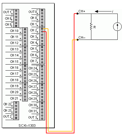
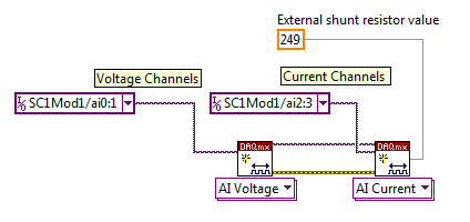
Yes it can. Although you will need external resistances (I recommend resistors precision for better accuracy) for current signals. The SCXI 1102 b is indirectly measuring the current by measuring the voltage drop across the resistance. The table below describes the current diagram and how it will seek in LabVIEW and DAQ assistant.
Wiring diagram
LabVIEW
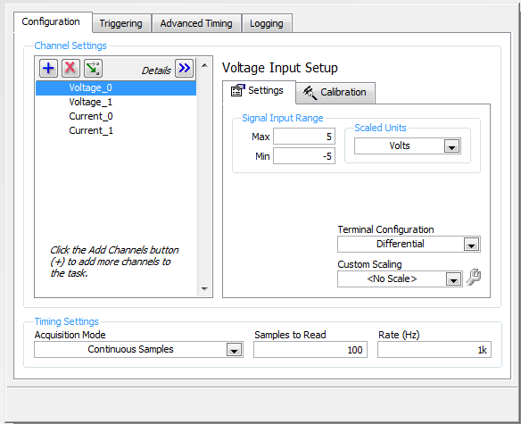
DAQ Assistant
Kind regards
Izzy O.
Technical sales engineer
National Instruments
NI.com/support
-
Measurement of temperature using Iex thermistor with PCI-6259
Hi all
I have I encounter some difficulties to measure the temperature using MAX with the installation of the thermistor Iex and would like to know if I missed something important. I use external current thermistor excited with 2 ladders and card PCI-6259 with MAX.
This is a channel that was originally set to measure voltage and MAX approx. 900mV since this channel, OK, the voltage converted temperature is about 30 ° C. Then I added a new channel and configured to measure the temperature directly with default installation MAX Iex thermistor. This is so the problem appears: I'll get a constant-273 C instead of 30 C as expected by operating the canal in MAX. I must have done something wrong here.
Your help is greatly appreciated!
Bryan
We discovered that the problem came from our wiring to thermistor does NOT of installation. If Differencial has been used, the conversion of MAX worked well. If this is not the case, only directly blood pressure will work. Bryan
-
AT & T changed their design of the homepage, and I liked the old one. A way to create my own homepage in Firefox using modules for content that I prefer? I liked the modules which gave me a variety of sources of news, finance, sports, weather, calendar, etc... It also allowed me to use a background of my own source. Finally, he allowed me to resize the modules I needed. I would like to be able to replace the new AT & T with my own homepage. Thank you.
Maybe http://www.netvibes.com/
-
programming LabVIEW 2010 how to scxi 1102 and 1503 cascade in scxi 1101 case
How to scxi 1102 and 1503 cascading if 1101 scxi for labview 2010 programming
just test ok
LabVIEW 2010 latest
-
Somehow in the Module Development Panel and the photo on overview of the evidence, whenever I do the change LR displays a box and asks me if I want to create a copy of the evidence. I click on the "do not show again". I don't want to use a snippet of evidence or never. It has replaced my histogram Panel and I can't seem to be able to go back and get out an excerpt from the evidence. Can someone tell me the secret of how to close the Soft Proofing function and return to normal development with a histogram Module?
Thank you very much
Stuck in the summary of evidence
Press the "S".
-
I've lost the ability to use the hue, Saturation and Luminance option in develop module. I now have the Calibration of the camera, which I never use. How to bring back HSL? Help!
Use the menu command
Window-> panels-> STL/color/black & white
-
SCXI-1102/SCXI-1303 undetected in SCXI-1000 chassis
I use an installer with the SCXI-1303 module in an SCXI-1102 module in a chassis SCXI-1000 measures voltage and thermocouple.
Until recently, everything worked well. but now it seems that I am unable to communicate with the interface. I've tried two different computers and hardware is not detected in MAX. The power light and fan on the SCXI-1000 chassis light again, it just seems to be no acknowledgement of the connection to the computer.
A few more specific error codes:
* When I double-click on the DAQ Assistant, in the block diagram window and click on 'Test' one of my entries, I received the following error message:
"88705 error: the specified device is not present or is not active in the system."* I also got the error code "error-89130: not available in NOR-DAQmx device" in Control Panel test DAQ Assistant
* During the closure of the DAQ Assistant test Panel, I see the error "error-89130: device not available for routing.
* To the MAX, if I try to 'test' the chassis or the module, I've seen errors either saying that the device is not detected, or that the device must be reset or is being restored, or the traditional DAQ drivers must be reset (I tried the reset suggestions without result)
At this point, I wonder if the Commission or the cable is pulled. Unfortunately, I don't have an other 68-pin cables to test at the moment.
Thanks in advance...
Thanks guys, I was able to solve the problem. To all those who might find this,
* I noticed in the Windows Device Manager that two PCI devices have been listed as being not installed correctly.
* After trying to update the drivers, I couldn't start the computer; got BSOD after the BIOS loading.
* Some research led me to go out two PCI cards that I was not using, and I moved also to reinstall my data acquisition on an another slot card to force material.
* Starts up, load drivers automatically and I'm gone.
Doesn't explain not why it did not work in the other computer, but in the words of Spinal Tap, the authorities have said it was better left unresolved at this point.
-
With the help of 1102 and 1308 cards for different input types
If I use maps 1102 and 1308 to receive both voltage and current signals, remove the resistance of the 1308 on channels, I don't want tension? I guess that is another way of asking, is it possible to always send the current signals "through" the 1308 directly to the 1102 so that I can use only one card of 1102 for my application?
Hello Jim,
Thanks for the clarification, I misunderstood the original investigation. When you reference the Manual for the SCXI-1308 module, it can be read on page 2 you can measure the current and voltage. In order to measure the voltage, you should remove the resistance of the current loop, and later, he identifies the resistance and their respective channels on the next page, 3. That said, delete the resistance won't be a problem.
Best,
-
best way to measure the thermistor
Hello!
We are looking for a solution for measuring temperature thermistor. I've read the material resources OR recommend for the thermistor measures.
Can you give me some ideas other alternatives for usable material temperature through resistance (we would use the default configuration, excitation of 2.5 Volts and a resistance of 5 + thermistor). So we need something capable of giving 2, 5V output and to measure the tension caused falling across the thermistor.Would be a NI USB-6009 suitable for this task? I guess that the resolution is not enough maybe?
Another option might be cheaper with a USB-GPIB interface Keithley 2010 multimeter, but in this case what should we use as a reference of tension?Thanks for the tips!
I want to second opinion to Henrik about repeatability in high resolution. Measures of temperature with Thermistors are particularly difficult. You have to worry:
- Auto-echauffants because of the power generated by the excitation current
- Time to balance the thermistor and electronic
- Stability of the excitation source
- Stability of the measuring device
In general, if you want something more than about 1% reproducibility, things start to me interesting. Of course, it's what makes it fun to do.
If you go the road of the sound card, remember that while most modern computers have quite high resolution a/d (sometimes up to 24 bits at 96 kHz) converters, you must watch the noise figures to get what you can actually solve. Off-board solutions (e.g., M - Audio Delta 44) will give you the best numbers of noise, since the ADCs are isolated from noisy inside your computer.
Good luck and have fun.
-
Signal acquisition of voltage AC using NI 9206 9205 and cRIO
Hello. I have difficulties accurately acquire a signal voltage AC using a module OR 9206 and cRIO. I'm looking to acquire signals of tension of the two types of current transformers Magnelab: divide the rope and the base. In Labview, I first fill out an array of size 2 500 with the signal of the sensor (DIFF mode), and then calculate the RMS of the table. For the core of split CTs, I'm able to acquire exactly reading the correct voltage (verified by measuring the match on the line using a power Analyzer Fluke 434 amp. For the CT string, however, using the same method of table/RMS, I am unable to gain precisely the correct voltage reading. Measure the amp on the line using the Fluke 434 PA, good the CT string tension should be 0.05v. Using the 9206 (DIFF mode), the RMS of the array gives a reading of 0.071 voltage. Now the interesting part is when I measure the voltage by using two different True RMS DMM, I get two different readings. A multimeter, a Klein CL2000, reads the voltage in 0.05v. Other multi meter, a Fluke 189 reads wrong to 0.071, the same that I get using LabView and NI 9206 release. I guess the question is how the Klein interprets the signal differently Fluke 189 and the NI 9206 via LabView module. A difference between the split-core and rope CTs, is that the rope CTs require a power external power supply 12-30 v AC or DC. I'm providing 12v DC. I tried several AC and DC voltages and still get the same wrong result. I am quite sure that it is not a question of power supply, although perhaps the integrator in the rope is the creation of a single signal. Any ideas? I appreciate any input.
Thank you
J.Grant
AK2DM:
Update - found solution
-
As some Menu items: Modules, Help Menu and Pocket Extension does not work after update to 17.0
As some Menu items: Modules, Help Menu and Pocket Extension does not work after update to 17.0
This may be caused by the Tab Mix Plus extension
Start Firefox in Safe Mode to check if one of the extensions (Firefox/tools > Modules > Extensions) or if hardware acceleration is the cause of the problem (switch to the DEFAULT theme: Firefox/tools > Modules > appearance).
- Do not click on the reset button on the start safe mode window or make changes.
- https://support.Mozilla.org/KB/safe+mode
- https://support.Mozilla.org/KB/troubleshooting+extensions+and+themes
You can try to install the latest Dev version of Tab Mix more if you use this extension.
See the sticky on the forum of Tab Mix Plus:
-
WHY don't pictures suddenly not appear or display in my personal messages gmail using Firefox 12.0 AND 13.0 but I can see the beautiful in IE9? This isn't a problem with the images being seen on Web sites or in emails from various sites like Amazon, Bloomies, etc.. It is a problem with the images, copied and pasted while composing mail in GMAIL and the other Windows Live email accounts, etc. It started suddenly yesterday when I still had version 12.0 Firefox. (there may be a few days, but I hadn't been reading emails too for a few days due to time constraints). This morning I tried to find some fix for this by searhcing constantly through the web and through the forums of Firefox here. I checked my version of Firefox and also check for updates after about 2 hours of research from the forums without success and I was about to just get rid of Firefox 12 because some people were just that frustration with finding no solution, when suddenly, I got a message from Firefox 'urge' Update update me Firefox 13. It was AFTER I had just checked an hour earlier to see if there's an update! I did this update to version 13.0, BUT again, I do not receive emails containing images with these images posted (messages sent from my other e-mail account for myself and also e-mails to a friend - the two images containing). However, I can send and receive your same emails through IE9 in my gmail account and see all of the images of the FINE through IE9. What gives? I am so tired of what's going on. It happened before about a year or two ago, but I do not remember how it was corrected for ever. According to me, it has been resolved by a Firefox patch, and no action on our part. And these 4 + hours of work on that is just crazy. WHO has that kind of time to devote to fix these defects that occur every time updates of Firefox? I can not even find any mention of the same show. Now I'm seriously behind. You talk about time constraints! Anyone else having this problem? Someone at - he found a cure yet?
Is he missing pictures then make sure you are not block images from certain domains.
- Check the permissions for the domain in the active tab in "tools > Page Info > Permissions.
- Check that the images are enabled: Tools > Options > content: [X] loading images automatically
- Check exceptions in "tools > Options > content: Load Images > Exceptions.
- See the tab "tools > Page Info > media ' for blocked images (scroll all the images with the cursor key).
If an image in the list is grayed out and there is a check mark in the box "block Images of..." and remove this mark to unlock the images from this area.
Make sure that you do not block the images of third parties, the pref permissions.default.images must be 1.
There are also extensions (Tools > Modules > Extensions) and security software (firewall, antivirus) that can block images.
Maybe you are looking for
-
Mac needs virus protection program
Mac needs virus protection program
-
Re: On Satellite U400 Bluetooth does not work with windows 7
Hello I have no model of Toshiba laptop U serious (satellite U400 - 10 L): PSU40E-00F00WAR) is XP OS. but I change to windows 7Since bluetooth does not I tried all the driver but not of their work can someone help me? Thank youBest regards Post edite
-
I try to use the theme of the 'system' for my front panel, and my orders and simple digital indicators converted (from 'modern'). However, I noticed that there is no indicator of stamp simple 'time' apparent on the system > digital (or elsewhere). Is
-
How can I get voice and data to work with the ASA 5505?
Here's the issue I'm having. Can I get a Cisco 7940 to work behind one site to another configured ASA 5505 and I can also get data to work behind it. However, when I try to create a separate Vlan for voice and data, it does not work. Our voice VL
-
I've lost all my acrobat adobe Pro XI files during a reinstallation of win7. How can I get the news I need to download and install Adobe Acrobat XI Pro?[Read https://forums.adobe.com/docs/DOC-7273][Ask in the correct forum allows... Left the connect