Memory of the PXI - 6562 Max per channel
I have two questions.
I have a PXI - 6562 and a data set is 256 MB (32 MB). I want to send the data in this dataset on a single axis of I/O serial. basically, I would like to spend my little of a set of data at the same time on both edges of the clock on an axis of IO. I don't like on the other IO pins. Is this possible with the PXI-6562 or all bits in each octet in the memory of the card corresponds to a specific channel.
If I can't send my data in series then I will accept that to encode every bit in my data set in the form of byte with a bit of data and the other zeros. This means that, for a set of data from 256 MB, I would need 8 times more memory 2048b. I understand that there are a total of 2 GB of RAM on the PXI-6562. Is this all addressable RAM in series? I can write the data of all the 2 GB of RAM for say 8 i/o ports?
gtg811q
With the PXI-6562 even if you want to only output a channel you must always write in a format of U8. So, as you describe you that a single bit, worries you, and you will need to set to 0 for the rest. This means that all data that you generate will be the value of 256 MB of data, because the smallest unit you can write with the HSDIO driver is the U8.
Now in regards to moving data on the two edges of both sides of the sample clock, this is called Double flow of data and is available with our devices OR 656 X and 6547 and 6548 devices. We have a developer area which details the DDR option more.
Advanced features of NOR-HSDIO: Double data rate
http://zone.NI.com/DevZone/CDA/tut/p/ID/6718
In reference to the memory of the generation, the width of the data to the memory of the generation is not configurable by the user. This means that if you have the 128 MB / channel option your total memory available per channel is 512 Mbit/channel. Because the width of the generation of data is set to 1 byte, and you get 4 times the memory per channel mode DDR with the 6562. The KB below explains the behavior. Look under the section 'Generation '.
Width of HSDIO and allowance data memory:
http://digital.NI.com/public.nsf/allkb/E5170A54988EF81A8625725A006103BB?OpenDocument
So, in summary, the total of 2 GB memory won't be available for a single channel, but you have a total of 256 MB/channel available for each channel. Since you are really interested in only one channel you will be able to write data from 256 MB to you. As you would put all your data on the memory of the card you have to the flow of the disc on your generator HSDIO card. To do this, we have some examples:
NOR-HSDIO Stream from disk (generation) using Win32 IO file:
http://zone.NI.com/DevZone/CDA/EPD/p/ID/5270
However, there will be a bottle neck on your PXI backplane data, because the basket max transfer rate will be around 100-110 MB/s you will not be able to cope with your generation session. Since you will write in U8s each sample is 1 byte, which means that the best you can hope to stream would be around 100 MHz or more.
We have not the cards LVDS SMU (PXI Expresss) which would allow you to have a superior data through-put, but if you do not necessarily need the LVDS, we have other options. I'm guessing you need LVDS or you would not the 6562.
The other option is to write you data in parallel in the 8-bit generation DDR and then use an external serializer for an 8 to 1, then you would be able to use all of the available memory and you would probably be able to fit all your data on the memory of the card and you do not have to stream from the disc. This external serializer allows you to put your first data point on channel 0, second data point on channel 1 and one until you loop around back and have your second sample generated between the way 0 be your 8th overall your waveform data point.
I hope this helps and let me know if you have follow-up questions. Thank you!
Tags: NI Hardware
Similar Questions
-
Single channel match trigger speed model vs onset of edge on the PXI-6562
I think that my question boils down to this: what function does the edge of trigger plan that is not provided by the model match trigger?
As far as I know, the only differnece on the PXI-6562 is the edge trigger has its own pins dedicated (PFI pins and pins RSTI) to detect a trigger, while the model match trigger detects a rising edge or falling on a regular input pin.
Is there a difference in performance (for example, the time to rearm)?
Are both triggers synchronous types with the sample for dynamic acquisition clock?
On my application:
I acquire a signal off a SPI bus, triggering the CS line. I start to acquire data when the CS line going down and stops when the CS line is high. As I acquire data CS on a regular supply, it seems logical trigger on a pattern for this channel only match. I'm curious to know if there is any advantage to connect a PFI PIN to my CS of entry so that I can start using digital edge type.
Thanks in advance,
Arthur
Arthur,
There is no difference with regard to performance using a digital camera compared to a type of pattern match trigger. Specifications for rearm time reference to the trigger type (Start, reference, etc.) in the samples to rearm, and there is no difference with the performance when you use a digital advantage over a line/PFI line Trigger and a correspondence to the model used on the input signal. Change the source of the trigger itself will not change the performance of the material that occurs after the trigger is received. This behavior to sync with the clocks of acquisition regardless of the input source. We're just looking at different sources for the jury to look for a given trigger.
-
samples per channel and the number of samples per channel
in my DAQ mode samples finished program, there are two screws: timing and read.vi DAQmx DAQmx.
I have to set the parameter to "samples per channel" DAQmx timing.vi and 'number of samples per channel' on DAQmx read.vi... Is there a relationship between these two?
My laser runs at 1 K Hz. I want to go to the wavelength, wait for a number of shooting lasers, read the data and move on to the next page...
Thank you
Lei
In your case, the VI will acquire the lesser of either:
The "samples per channel" that you have defined on the timing DAQmx VI
-OR-
The number of iterations of your for loop (N) times the 'number of samples per channel"that you have defined on the DAQmx read VI
The "samples per Channel" VI DAQmx of timing for a finite acquisition dictates how many samples the DAQ hardware should acquire in it's onboard buffer before indicating that the acquisition is complete. "The number of samples per Channel" on the read DAQmx VI dictates how many samples the DAQmx driver must return buffer on board the aircraft to your application.
Let's say the "samples per channel" on the calendar DAQmx VI is set to 50. Thus, the card will acquire 50 samples and place them in the edge of the buffer, then stops. Suppose we have the 'number of samples per Channel"on the DAQmx reading VI the value 3 and what we call the VI in a loop For which runs 10 times. Thus, every time the DAQmx lu VI is called, it will wait until there are at least 3 samples in the buffer, and then return these three. We call the VI a total of 10 times, then we will answer 30 total samples. Thus, the last 20 samples acquired the card remains in the buffer and are destroyed when the task is disabled.
Now let's say that we increase the "number of samples per Channel" on our DAQmx Read VI at 10. VI Read will wait until 10 or more samples are in the buffer, and then return these 10. Thus, we will be back all 50 samples map acquired by the 5th iteration of the loop For. The 6th time we call him VI DAQmx Read it expires, because there will never be another 10 samples in the buffer, and the VI returns a warning.
This clarifies things?
The purpose of this behavior is to allow you to both set the total number of samples that the DAQ hardware will acquire and also control how much of these samples is returned whenever you call the DAQmx Read VI.
Kind regards
-
How to determine the amount of memory on the PXI-5124
Can I determine the amount of memory on the PXI-5124 visually? I don't see a reference as 778757-02 on the map.
Hello axiomtest,
There are two stickers on the back of the card (including one with a barcode) and the other without. The part number is that without the bar code and from there, you can search your memory option on our Web site. If there is no sticker on the card, which looks like yours have been removed, then use this example of community in LabVIEW to determine the size of your card.
Kind regards
-
Upgrading memory on the PXI-8105 controllers and PXI-8106
Hello
I've recently upgraded the memory of three PXIs; one with a PXI-8105 controller and two with the PXI-8106 controllers. Both the 8105 and 8105 can have a maximum of 4 GB (2x2gb) DDR2-677 (PC2-5300) (see links below). However, on the three systems, both the BIOS and the o/s only see 3.3 GB. No idea why this might be the case?
I tried to Flash the BIOS (v1.4 on the two PXIs), but without success.
We use COTS memory (i.e. not purchased NOR) but I would be badly pushed to believe it is the cause of the problem.
Thank you.
Links;
- The PXI-8105 http://sine.ni.com/nips/cds/view/p/lang/en/nid/202630 max memory capacity
- The PXI-8106, http://sine.ni.com/nips/cds/view/p/lang/en/nid/203442 max memory capacity
- Update BIOS page: http://digital.ni.com/public.nsf/allkb/9C9362590B05CD6E86256B270082164A
I don't know about the BIOS reports less than 4 GB. Here's a blog post that best describes what I wanted.
-
Question about reversal of pin of the PXI-6562
I have a PXI-6562 card with cable which is the note.
Note If you create a customized with connector wiring solution (779157 - 01) and cable (192744-01), the NI 656 x pinout is reversed at the level of the end fitting. For example, the signal on pin 1 on the previous figure would map to pin 73 at the level of the end fitting.
Pin 1 go back to pin 73, but what about the pairs?
Pin 2 return to 71 or 72?
1 - 73
2 - 72
.....
73 - 1
All pin codes signals add up to 74
-
How to access memory on the PXI-8106 controller
I am able to write and read the brief on PXI-8106 using FTP functions in labview. But I'm not able to find a way to delete data that I wrote (PXI-8106) memory. Y at - it an easy way to do it.
Thank you
Kitenge
Kitenge,
Is this something you want? - Delete the file from the server FTP using the Internet Toolbox
-
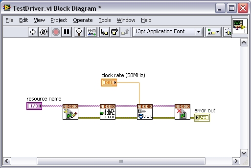
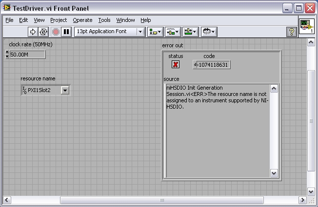
Error-1074118631 after driver update "the name of the resource is not attributed...". "PXI-6562
I just updated my version 1.5.3 to 1.7.4 niHSDIO driver and now the device, a PXI-6562 is won't boot. I get the following error. The VI is suspended for 30 ~ 60 s attempt to initialize before the error occurs.
Code: - 1074118631
Message: niHSDIO Init generation Session.vi
the name of the resource is not assigned to an instrument supported by NOR-HSDIO. The device worked fine with the old driver.
Windows Device Manager indicates that everything is installed and working.
I tried to write a simple VI by using new versions of the screw HSDIO and recreating the I/O resource menu drop-down.
The resources dropdown lists the name as "PXI1Slot2".
I can see the device in MAX thanks its location listed as "chassis: 1; Slot: 2 "
The PXI-6562 has 2 LEDs on the front panel for 'access', 'active'. No lights during an attempt to initialize.
I tried uninstalling the driver in Windows, reinstalling and restarting: same problem.
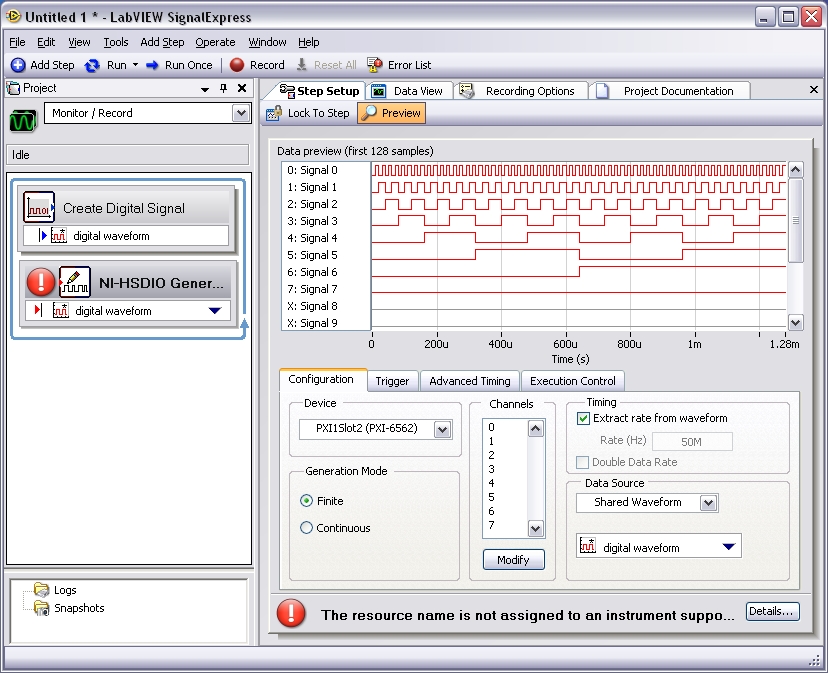
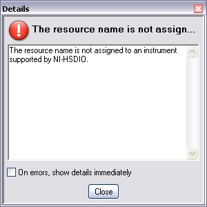
I tried to use the device in Signal Express, and it produces the same error.
I use LabVIEW version 8.5 and Signal Express 2.5.
Does anyone know how to fix this?
Thank you
Arthur
Hey Arthur,.
You should also do a repair on the NOR-DAQmx driver for example, after you have repaired HSDIO. Let us know how it goes. Thank you.
Kind regards
DJ L.
-
Hello
I'm trying to trigger the capture of the PXI-6562 with multiple PFI. Since I did not extract the available channels, I can't use pattern trigger. My idea is to have PFI0 and PFI1 as a trigger. So, the DIO card begins to capture data when PFI0 = HI and PFI1 rising edge.
I don't know if the PXI-6562 is able to do. I just want to avoid the construction of any additional hardware.
Thank you!
Andy
Hi Andy,.
Unfortunately, the PXI-6562 does not support the combination of trigger for the acquisition of the PFI lines you describe. A trigger pattern to achieve match but only if you use a combination of the DIO lines. Otherwise, for the generation, perhaps you could implement this with two separate script triggers and a condition statement. For you the request, I would recommend using a simple gate circuit to let the relaxation through when the other line is high. A door AND would also work.
I would like to know if this helps, good luck!
-
How to determine the amount of memory shipped on the PXI-5114
How to determine the amount of memory onboard, I have on my PXI-5114?
Thanks in advance.
Hello
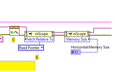
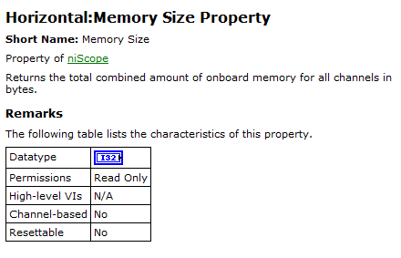
I'm sorry I didn't know you already had the map. There is a property for NO-Scope node to determine the total amount of available memory that we can then divide down to get the memory available per channel. Please see the vi and help below:
This gives a shot, just drop it in a VI that you use and if it should return your memory cards. If you don't have a LabVIEW I can probably retrieve the purchased version by querying your serial number.
Kind regards
Kyle S
-
Extract and save all the channels of the PXI-5105 with 4 M of edge detection... Help!
Dear collegaues!
Please help me to improve my request, exhibit attached and sorry for my English.
So my task is to extract and save all the channels (eight) of the PXI-5105 with 4 M of detection of peaks and sample rate 4 M with loop 1 sec...
Entered all my channels are wiring detectors NaI with 0, 5... 1 microsec pulse (really) width and 0 kHz at not more than 40 kHz freq.
Why I chose the registration of 4 M and the sampling frequency of 4 M namely? Answer is that I tested previously PXI-5105 40 kHz generator and pulse width 0.5 microsec. It works great and detection of peaks indicate 40000 pulses/s for me. If I set lower than 4M record and sample rate of 4 M, it is without work. In my honest opinion record 4 M and the frequency of sampling of 4 M are parameters very min.
In the detection of peaks time present only 6 working channels... When I connected to diagram more 6 "detector.vi peak" - I see the error "...". out of memory... ».
Advise me please, what needs to be done to it, it's all working well.
-
Configuration of the individual channels on the PXI-4472 b
Hi, I use the card PXI-4472 b to acquire data of vibration using sensors with different frequency ranges. The problem I have is that some of the transducers require being fed by the jury (via IEPE) and some don't and I can't find a way to turn the excitement on and off for individual channels, only each other.
I am using LabVIEW 8.6 and that you have configured all channels using the nodes property to activate the excitement and specify the current, but not all channels require that.
It says clearly in the data sheet of the map of 4472 channels are individually configurable for the IEPE, can someone please tell me how to proceed?
Thanks in advance,
Darren.
Howdy Darren,
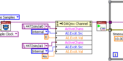
Please see the following screenshot that illustrates how to set different values for different channels of IEPE all in a single task using DAQmx. The key point here is the property of ActiveChans. Otherwise, as you know, 3GEF55NQ knowledge base: How can I activate IEPE excitement on my DSA in DAQmx device? would do the trick.
I hope this helps!
-
Synchronization of HAVE several devices in the PXI by the Sub - VI of DAQmx create channel
Hello
There are two PXI-6123 cards in the slots of the PXI-8109, and then I would acquire the simultaneous analog input signals.
The manual of the PXI-6123 recommended with a common time as a master Timebase and base to the slave devices.However, I wonder if I can take advantage of the method as the accessory, including all channels to HAVE the devices in the physical channels to create.
Does it work? How can I know what are the "some data acquisition hardware OR" in the passage of the attachment?
Hello
Please refer to this KB: http://digital.ni.com/public.nsf/allkb/78E44565FD87E7D686257108007F94F8. I think that you are good with your two PXI-6123 devices, if only you DAQmx 8.1 or later installed. If please come back and let us know your test result.
Thank you
Phil
-
Read the PXI-8431 channels using LabVIEW
Hi Marc,
The examples provided with LabVIEW and DAQmx drivers are very detailed and comprehensive to demonstrate how you can use cards. To join the Finder of the example, start LabVIEW and select help > find examples.
When you load the example Finder, make sure you browse by task.
For the programming of DIO:
Navigate to hardware input and output > DAQmx > digital measurement. There is a few screws. Make sure you look in the list of requirements to see the example works with the PXI-6515.You can also visit the following links to learn more about programming DAQmx:
Getting started with NO-DAQmx
http://zone.NI.com/DevZone/CDA/tut/p/ID/5434
Learn 10 functions in NOR-DAQmx and handle 80% of your Applications of Data Acquisition
http://zone.NI.com/DevZone/CDA/tut/p/ID/2835For series programming:
Navigate to hardware input and output > Serial
You will find most of the screw example it can be used with the PXI-8431.I hope that helps you to get off the ground!
-
Change in gain on the PXI-6221
Hi all
I apologize in advance for a newbee question. I recently started to work on the measurement of force in the laboratory of fluid mechanics. We got a load cell 3 - axis with 0.5 mV/V, power per channel, which I hung on SG24, which sits on SC-2345, connected to the PXI-6221.
As far as I understand, after the signal comes out SG24 unit, it is amplified to 500mV and powered to PXI card, which in turn have 4 possible gains of 0.2V, 1V, 5V, 10V. To keep the resolution as fine as possible, I'd be interested take a +/-200mV gain, which in turn cut my signal more then half but keep a resolution ~ 6.1uV, I like not having the range, my forces expected fall shorter reach.
The problem is that I can't find neither manual or MAX a way how truly change the gain. If I open MAX > NOR-DAQmx devices > PXI-6221, I see no possibility to change the input voltage. I can see +/-10V in the Test Panel, but if I change to +/-200 m it resets at + /-10, after I close and reopen again.
Can someone help please on this issue?
Thanks in advance
Hi Chris,
You made my day
 )
)Thanks a bunch!
Maybe you are looking for
-
my phone begins to show the alert of low storage since yesterday. After the removal of a few photos and videos, I managed to release about 1 GB of space. But the low storage alert popped up again in just 15 minutes. I have not download or update the
-
Tecra A - how to remove finger prints?
Hello I remove all the fingers of my laptop fingerprint reader. I can't remove the fingerprints of other users with the Inspector memory fingerprint. File aid Protector Suite QL and computers laptop manual says that it should remove the button in the
-
help me stop the spinning wheel
spinning wheel is almost constant. 2011 iMac; over 400 GB of free storage
-
Download file with LabVIEW webservices
Hello community, I have running on a PC webservice and I would that my users to be able to log on the site (made), select the menu upload (done), select the file they want download (done), then using a POST method, I need a routine that acutally down
-
Windows Explorer displays the size of the file in KB?
I have windows 7 32 bit. How can I change the sizes of MB or GB instead of KB file?