PXI-6562 Multiple trigger
Hello
I'm trying to trigger the capture of the PXI-6562 with multiple PFI. Since I did not extract the available channels, I can't use pattern trigger. My idea is to have PFI0 and PFI1 as a trigger. So, the DIO card begins to capture data when PFI0 = HI and PFI1 rising edge.
I don't know if the PXI-6562 is able to do. I just want to avoid the construction of any additional hardware.
Thank you!
Andy
Hi Andy,.
Unfortunately, the PXI-6562 does not support the combination of trigger for the acquisition of the PFI lines you describe. A trigger pattern to achieve match but only if you use a combination of the DIO lines. Otherwise, for the generation, perhaps you could implement this with two separate script triggers and a condition statement. For you the request, I would recommend using a simple gate circuit to let the relaxation through when the other line is high. A door AND would also work.
I would like to know if this helps, good luck!
Tags: NI Hardware
Similar Questions
-
Single channel match trigger speed model vs onset of edge on the PXI-6562
I think that my question boils down to this: what function does the edge of trigger plan that is not provided by the model match trigger?
As far as I know, the only differnece on the PXI-6562 is the edge trigger has its own pins dedicated (PFI pins and pins RSTI) to detect a trigger, while the model match trigger detects a rising edge or falling on a regular input pin.
Is there a difference in performance (for example, the time to rearm)?
Are both triggers synchronous types with the sample for dynamic acquisition clock?
On my application:
I acquire a signal off a SPI bus, triggering the CS line. I start to acquire data when the CS line going down and stops when the CS line is high. As I acquire data CS on a regular supply, it seems logical trigger on a pattern for this channel only match. I'm curious to know if there is any advantage to connect a PFI PIN to my CS of entry so that I can start using digital edge type.
Thanks in advance,
Arthur
Arthur,
There is no difference with regard to performance using a digital camera compared to a type of pattern match trigger. Specifications for rearm time reference to the trigger type (Start, reference, etc.) in the samples to rearm, and there is no difference with the performance when you use a digital advantage over a line/PFI line Trigger and a correspondence to the model used on the input signal. Change the source of the trigger itself will not change the performance of the material that occurs after the trigger is received. This behavior to sync with the clocks of acquisition regardless of the input source. We're just looking at different sources for the jury to look for a given trigger.
-
Simultaneous sampling using two cards PXI-6562
Hi all
I was wondering if it is possible to have two examples of cards PXI-6562 (e/s LVDS high flow) at the same time using the same trigger?
Thanks in advance,
Nathan
Hello
You can synchronize certainly several MSC devices, including modular instruments to NI HSDIO. The most effective way to proceed is to use the NOR-TClk synchronization API. It is provided with several of our drivers of modular instruments and devices, including NOR-HSDIO. The first part of this knowledge base explains the use of the NOR-TClk functions for that. This tutorial gives a very thorough introduction timing and synchronization using the API OR-TClk.
If you are more concerned with programming in fact such a request, I would check the NOR example Finder for some good examples. "" "" Navigate up to material input and output "modular instruments and devices" NOR-HSDIO "synchronization" to several features of dynamic Acquisition (TClk) .vi
Jon S
-
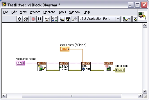
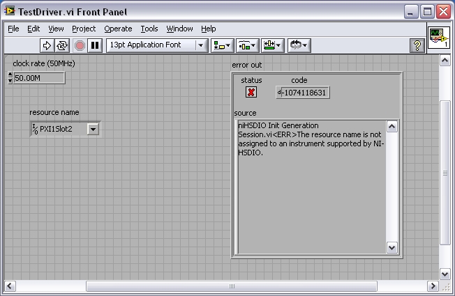
Error-1074118631 after driver update "the name of the resource is not attributed...". "PXI-6562
I just updated my version 1.5.3 to 1.7.4 niHSDIO driver and now the device, a PXI-6562 is won't boot. I get the following error. The VI is suspended for 30 ~ 60 s attempt to initialize before the error occurs.
Code: - 1074118631
Message: niHSDIO Init generation Session.vi
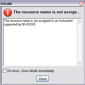
the name of the resource is not assigned to an instrument supported by NOR-HSDIO. The device worked fine with the old driver.
Windows Device Manager indicates that everything is installed and working.
I tried to write a simple VI by using new versions of the screw HSDIO and recreating the I/O resource menu drop-down.
The resources dropdown lists the name as "PXI1Slot2".
I can see the device in MAX thanks its location listed as "chassis: 1; Slot: 2 "
The PXI-6562 has 2 LEDs on the front panel for 'access', 'active'. No lights during an attempt to initialize.
I tried uninstalling the driver in Windows, reinstalling and restarting: same problem.
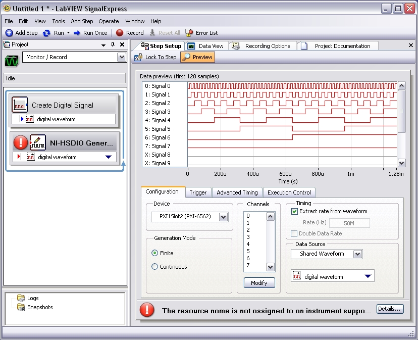
I tried to use the device in Signal Express, and it produces the same error.
I use LabVIEW version 8.5 and Signal Express 2.5.
Does anyone know how to fix this?
Thank you
Arthur
Hey Arthur,.
You should also do a repair on the NOR-DAQmx driver for example, after you have repaired HSDIO. Let us know how it goes. Thank you.
Kind regards
DJ L.
-
Question about reversal of pin of the PXI-6562
I have a PXI-6562 card with cable which is the note.
Note If you create a customized with connector wiring solution (779157 - 01) and cable (192744-01), the NI 656 x pinout is reversed at the level of the end fitting. For example, the signal on pin 1 on the previous figure would map to pin 73 at the level of the end fitting.
Pin 1 go back to pin 73, but what about the pairs?
Pin 2 return to 71 or 72?
1 - 73
2 - 72
.....
73 - 1
All pin codes signals add up to 74
-
Memory of the PXI - 6562 Max per channel
I have two questions.
I have a PXI - 6562 and a data set is 256 MB (32 MB). I want to send the data in this dataset on a single axis of I/O serial. basically, I would like to spend my little of a set of data at the same time on both edges of the clock on an axis of IO. I don't like on the other IO pins. Is this possible with the PXI-6562 or all bits in each octet in the memory of the card corresponds to a specific channel.
If I can't send my data in series then I will accept that to encode every bit in my data set in the form of byte with a bit of data and the other zeros. This means that, for a set of data from 256 MB, I would need 8 times more memory 2048b. I understand that there are a total of 2 GB of RAM on the PXI-6562. Is this all addressable RAM in series? I can write the data of all the 2 GB of RAM for say 8 i/o ports?
gtg811q
With the PXI-6562 even if you want to only output a channel you must always write in a format of U8. So, as you describe you that a single bit, worries you, and you will need to set to 0 for the rest. This means that all data that you generate will be the value of 256 MB of data, because the smallest unit you can write with the HSDIO driver is the U8.
Now in regards to moving data on the two edges of both sides of the sample clock, this is called Double flow of data and is available with our devices OR 656 X and 6547 and 6548 devices. We have a developer area which details the DDR option more.
Advanced features of NOR-HSDIO: Double data rate
http://zone.NI.com/DevZone/CDA/tut/p/ID/6718
In reference to the memory of the generation, the width of the data to the memory of the generation is not configurable by the user. This means that if you have the 128 MB / channel option your total memory available per channel is 512 Mbit/channel. Because the width of the generation of data is set to 1 byte, and you get 4 times the memory per channel mode DDR with the 6562. The KB below explains the behavior. Look under the section 'Generation '.
Width of HSDIO and allowance data memory:
http://digital.NI.com/public.nsf/allkb/E5170A54988EF81A8625725A006103BB?OpenDocument
So, in summary, the total of 2 GB memory won't be available for a single channel, but you have a total of 256 MB/channel available for each channel. Since you are really interested in only one channel you will be able to write data from 256 MB to you. As you would put all your data on the memory of the card you have to the flow of the disc on your generator HSDIO card. To do this, we have some examples:
NOR-HSDIO Stream from disk (generation) using Win32 IO file:
http://zone.NI.com/DevZone/CDA/EPD/p/ID/5270
However, there will be a bottle neck on your PXI backplane data, because the basket max transfer rate will be around 100-110 MB/s you will not be able to cope with your generation session. Since you will write in U8s each sample is 1 byte, which means that the best you can hope to stream would be around 100 MHz or more.
We have not the cards LVDS SMU (PXI Expresss) which would allow you to have a superior data through-put, but if you do not necessarily need the LVDS, we have other options. I'm guessing you need LVDS or you would not the 6562.
The other option is to write you data in parallel in the 8-bit generation DDR and then use an external serializer for an 8 to 1, then you would be able to use all of the available memory and you would probably be able to fit all your data on the memory of the card and you do not have to stream from the disc. This external serializer allows you to put your first data point on channel 0, second data point on channel 1 and one until you loop around back and have your second sample generated between the way 0 be your 8th overall your waveform data point.
I hope this helps and let me know if you have follow-up questions. Thank you!
-
A scanner to trigger a DMM does
Can I implement a digitizer PXI-5102 to trigger a PXI-4060 DMM to acquire several measures? The entry of the PXI-4060 DMM is used to communicate with SCXI cards in my 1050-PXI chassis, so I need to trigger the PXI-4060 DMM software.
Thanks in advance.
Yes you can. You can route the trigger of the 5102 at the bottom of the basket and the PXI-4060 triggered from this line of tripping from the backplane.
-
material missing triggers hdio? (PFI0)
I use (or rather try, for now) to use the HSDIO card for acquisition as follows:
Script generation according to schema: (l1, wrtcfg1, wrtlat are the wave forms long 1000clock)
script myscript
generate a l1
Repeat 10
generate a marker0 wrtlat (0)
generate a marker0 wrtcfg1 (0)
end repeat
end of script
Marker0 is exported (correctly) to PFI0. Same line is set up to run at acquiring data (records multiple, both start and advance Trig point to the same PFI0 signal). For test purposes I do this with SMA2164, where Channel 6 (wvfm sent to DUT) is connected directly to the ch4 (received wvfm of HAD) to get rid of the possible influence of the HAD. What worries me is that I seem to take _half_ of the signals I generate, rather than all. The attached vi has two loops of independent test, the generation timed a (every second, making the above script), which means generation 2xrepetitions (20 in the example above) trigger pulses on PFI0 (scope proves this hypothesis being right). However, the second for loop - part acquisition (iteration of 20 records each loop CQI, timeout 10 s), which should in principle work once by each iteration of loop generation runs only every second.
I would be grateful for my mistakes to score.
Michal
PS: Checked behavior on two different configurations, one with PCI-6562, second with PXI-6562. Both Miss the triggers of the PFI line (no difference which) in the present scenario.
Hello
I just read your message. In your case I would suggest using the Insider/Fetch combination rather than read (Fetch is better when you need to acquire data and expect that the triggers). It is also important to remember that you must initialize first acquire the task and then generate task (in your case first trigger is generated after 10 ms, which may not be sufficient for the task of acquiring start).
Please find sample application that:
1 initializes the acquisition of 1 s after tripping to Marker 0 (line 0 PXI)
2 generates the trigger (line 0 PXI) and 1 s data
3 generates 1 s of zeros
4 generates the trigger (line 0 PXI) and 1 s dataTask of acquisition has to read data only from points 2. and 4.
Hope this helps,
Best regards
Michal -
None of RNS, te0 & te1 clock source work except OnbordClock for cDAQ9174?
acquisition system used: cDAQ-9174, NI9206, Labview2009, OR-DAQmx 9.2, MAX 4.7.1
Referring to the "specifying different sample rates for CompactDAQ Modules multiple", following time engines could be used for cDAQ9174 (AI, te0 & te1)
/ cDAQ1/I/SampleClock
/ cDAQ1/TE0/SampleClock
/ cDAQ1/TE1/SampleClock
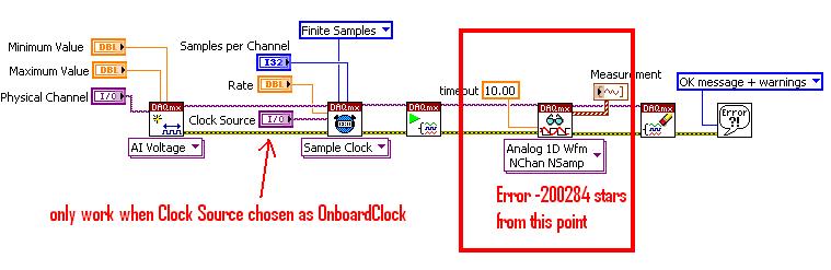
However, for the voltage-Clk attached Acq Select.vi, none of the above clock works unless OnbordClock is selected. Can someone explain this please?
Hi NCLbingji,
'Source' entry "DAQmx Timing (sample clock) .vi" tells DAQmx to get the sample clock a PFI PIN or another subsystem (such as AO, DIO or counters). It has not been designed to choose what sync engine to use. I think that the example of the community that you mentioned is defining the sample clock source incorrectly.
On a device with a single timing engine of HAVE, like cDAQ-9172, ' IA/SampleClock' by specifying the source of the sample clock I tells DAQmx to deliver the sample clock GOT to the sample clock, which he cannot do it, then it gives you a more useful error:
"Error-89131 occurred in DAQmx start Task.vi:8 '.
Possible reasons:
Attempted to perform an itinerary when the source and destination are the same terminal.
In many cases, like when you configure an external clock or counter source, you must select a PFI, PXI or RTSI trigger line as the terminal of the source.
Property: SampClk.Src
Property: SampClk.ActiveEdge
Source device: Dev1
"Terminal source: AI/SampleClock.A cDAQ-9174, DAQmx chooses the timing engine when you book the job. The timing engine he chooses does not necessarily match the timing engine that you specify in the VI. If it does not match (for example your VI specifies te1/SampleClock, but DAQmx choose te0), then your task will wait for Terminal produce some clock pulses. Because there, there is no clock on this terminal, the task eventually times out and returns the error-200284 (samples not yet available).
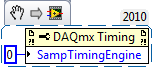
The correct way to explicitly specify what sync engine to use is to set the SampTimingEngine property.
Unfortunately, the table of values for this property by using NOR-DAQmx for 9.2.x version is also incorrect (reported to R & D such as CAR #239502). Here are the correct values:
- 0 selects te0.
- 1 selects te1.
- 2 selects HERE.
You can also leave DAQmx choose a timing engine, then ask that you chose. To do this, choose the task and then get the value of the SampClk.Term property.
Brad
-
NIMax.exe - Entry Point not found - attempt to create the task in MAX
I have two different cards using NOR-DAQmx: PXI-4461 and PXI-6259. They are installed in a PXI-1031 chassis with a PXI-8105 controller. Both devices pass their self-test in MAX. When I try to create a new task for either, I get first the expected selection dialog box:
Once I selected "Analog Voltage" (or anything else), I get the following error:
Last week I upgraded my to a PXI-6562 HSDIO driver, who led me to update NOR-DAQmx to 9.2.3 and repair the two installations of Windows to get their work (see this forum thread).
Creating task used to work. The system always recognizes one of the tasks I created there are weeks for the PXI-4461.
Here's a screenshot of my current versions of software:
Does anyone know how to fix this?
I solved this problem by downloading and installing the driver OR DAQmx 9.3.0. This, in turn, has caused the problem of the post I linked above, which I fixed it by choosing 'fix' in the control panel to 1. the HSDIO driver, then 2. the NOR-DAQmx driver. The order of the questions. Now, it seems to work.
-
Salvation;
I have an SMU-1065 with the following modules: PXI-6529, PXI-6280, PXI-5114, & PXI-6713. I have 3 questions:
1. how the RTSI is launched?
2. how this trigger can be monitored?
3. How can I create a task is triggered RTSI?
I'm fairly new to LabVIEW but I work with other more experienced programmers.
Thanks for any help.
4BoysDad
Hello 4BoysDad,
Before talking about your questions, I will provide some information about the cards you because I think it will help me to answer the questions completely. First, the PXI-6529, the PXI-6280, PXI-6713 uses the DAQmx driver but the PXI-5114 is a digitizer and uses the driver NOR-Scope. Knowing this, I would focus on the passage of relaxing between 3 maps DAQmx first before thinking about the PXI-5114.
At the same time, you have an SMU-1065 chassis. With this chassis, there are 3 segments of trigger bus essentially dividing backplane. If one of these cards is in a different segment, you'll have to correct bus together segments to spend relaxation through the bottom of basket. To see how backplane it broken up, please look at the Datasheet for the SMU-1065. I would recommend that you put them on a PXI trigger bus segment.
With that in mind, here are my answers to the questions:
1.) how is initiated the RTSI trigger? How to create a task is triggered RTSI?
Before doing so, you will need to select a master device to the other slave devices. If the master device is a DAQmx device and you are passing to an another DAQmx slaves, here's a example of how to implement this. The relaxation will be initiated by the master device and in this example, the trigger is a beginning arm (for more information about this, please see the DAQmx help). Looking at this example, the RTSI trigger is managed in the synchronization of tasks - Trig Skew correction. With outbreak RTSI, this VI also allows you to synchronize the clocks of reference for each of the devices. Given that this example provides detailed notes as well as step-by-step instructions how it works, I will not repeat the information here.
If you want to synchronize the card extended with DAQmx device or multiple devices, you will need to export the signal to the other card. This example explains how to implement the scope as a master and the DAQmx device as slave. As others explain, it provides a general explanation how to achieve this as well as step by step instructions how to implement this.
2.) how this trigger will do?
Regarding surveillance of relaxation, I looked in the DAQmx and the pilot of scope but also consulted with my colleagues, and it is not a function, we found who will tell you that the shutter has been sent. We found one way to check this is to use the timeout for task/sessions to see if they started. If they have not the trigger has not yet been sent to the other device. You are looking for this feature for debugging purposes or will you for use in your program somehow?
If you have other questions about this, feel free to post.
-
How to export via the trigger star pxi to several dvices
Hello
I have huge problems to do this work and free time to try rarely. Joined my unfinished VI (SyncTrig - Test.vi) who needs to synchronize 9 x PXI-4472 & 1 x PXI-6713 on PXI-1006 chassis (made up of bus 3 x 6 slots). Master ST in the #2 Groove is DSA (PXI-4472), the rest 8 x DSA are inserted in slot #3-#10, and MIO (PXI-6713) is in slot #11. I need MIO to generate signals of x AO 2 (ao0:1 or ao6:7) of arbitrary length. DSAS acquire 72 x channels HAVE simultaneously until the last pair of samples AO is triggered (AO and I work at the same pace).
I understand there are 2 ways to cynchronize a all these devices - to use reference clock 10 MHz from backplane, or Star trigger bus. Trigger the beginning of ST control is supposed to start all 10 devices. I couldn't do the 'references', examples and I managed to do the "StarTrigger" example works with 2 devices so I decided to stay with the latter. Of course, I hardly expect export usable for the PXI-6713 SampleClock and we hope to get help on this forum.
Here are my 3 questions/dilemmas:
1 grouping DSAS more in a single task & export clock via ST each
I've separated the master of ST in the UpperTask export SampleClockTimebase via the bus ST and StartTrigger through the spine. The rest of the DSA are grouped in a single MiddleTask since NEITHER-DAQmx makes it easier for this type of devices PXI. In VI, UpperTask exports in a single PXI location.
Is it possible to format the string to export the clock via ST to the multiple (all the) SHAS so they can all receive it grouped together in the unique MiddleTask? Or should I use a loop for export the time base clock 8 times and feed it 8 times for all slots #3-10?
Please be specific.
2 synchronization MIO with DSA master ST via bus from ST
How can I use the TimingNode to implement SampleClockTimebase division, so that the PXI-6713 can use it in the #11 slot (LowerTask)? If this is not possible via the ST bus, can someone please show me what TimingNode (s) to use to export usable St master clock and get to MIO to synchronize the HAVE and AO closely?
3 triggers of PXI chassis
I left 2-7 as 'Dynamics' triggers to be available for NOR-DAQmx. Is it enough for the configuration shown above, from PXI devices occupy 2 of 3 independent buses in PXI-1006?
BTW, I tried a different approach (SyncTrig - No. AO.vi), but the mistake of resting LowerTask just after his TimingNode power.
Ladies and gentlemen, I hope power affirmative responses because the documentation is completely absent on synchronization PXI DAQmx and are completely dependent on WEB resources.
Thank you in advance,
-
5154 PXI trigger on the external input
I use a PXI-5154 and want to change my previous program to trigger the external source. I'm feeding the external source from source to V 2.5 and it seems to trigger fine. However when data acquisition the vertical range of the oscilloscope will 5 V which is too high as to my request I acquire in the millivolts range. I tried to show the vertical range of the channel I acquisition, but although I put it as the active channel I get the following error:
Error 1074118616 has occurred to the property node (arg 1) in PD_measurements_v11_test.vi
Get a base attribute value channel failed because the channels interviewed have different values. Please specify a channel when you query a string based attribute.
I enclose you a printsceen of the relevant part of the code.
Kind regards
Karavellas
Dear Tunde
I managed to make the changes you suggested and the works of the example. I'll look in my code and see what the problem is. I'll get back to you if it has been fixed in my code or not.
-
How to delay a PXI-5122 trigger before routed to string of PFI
Hello world
I use a PXI-5122 in a PXI chassis. I want to synchronize with two external devices. The first will send a trigger (with a 10 Hz repetition rate) for PXI-5122. Then PXI will generate a trigger (with a constant delay) in the second.
It seems that I need to generate a trigger, then export this trigger to PFI 0 line, but I do not know how to delay triggers with a timeframe of 4µs. I read that there is a slight delay between a trigger on the PFI and the first sample. And the length of the cable is also an important factor to consider.
Could someone give me some suggestions?
Wednesday,
Thanks for the drawings, that helps a lot! Somehow, I see this work (how to set up the scanner):
1. set up the record length to be 12us (4us trigger samples, 8us after outbreak). If the sampling frequency is 100 ms/s, that would be a record length of 1200 samples.
2 configure the position of record reference to 33%. That's how the digitizer breaks 1200 400 samples according to trigger before triggers and 800 samples.
3. configuration of triggering immediate reference. This will allow the acquisition of trigger the moment she gained 400 before triggering samples.
4. export the "reference trigger (Stop)" to send to Device_2. This output pulse is of variable width, so if you want consistency, you will need to the Device_2 trigger the rising edge of the pulse, did not not fall m. Once 400-pre-trigger samples are acquired, this impulse will be sent, and then the scanner will be immediately habitable after initiation of sampling.
5 configure the trigger of the entrance of Device_1 (10 Hz trigger), as the 'Advance trigger' and 'Start Trigger'. This will make the digitizer wait this impulse to start sampling before the next record. We set up, the relaxation of beginning to the 1st record and the trigger in advance for all subsequent records.
This facility should allow a pretty decent timing, but please test to be sure that it will be sufficient for your application.
Kind regards
Nathan
-
Unable to trigger pxi-5105 exported signal pxi-4461
Hello
I use a chassis PXI-1033 with a PXI-4461 (daq) in slot 2 and 4-PXI-5105 in slots 3-6. I want to use the 4461 to export a reference trigger signal to of the 5105, but when I try to run my program I get the following error:
Error-89126 occurred at DAQmx Read (Analog DBL 1Chan 1Samp) .vi:1
Possible reasons:
Trigger line asked could not be booked because it is already in use.
Property: RefTrig.OutputTerm
Property: RefTrig.Pulse.Polarity
Target unit: PXI1Slot2Task name: _unnamedTask<89>
The Subvi I use to export the signal is built off an example I found. At the moment it is only under the scope of my code mode (I'll take care of the datalog part later). I'm not sure what I'm doing wrong, any help is greatly appreciated.
Thank you
John
Hi John,.
T Clk select a PXI_Trig lines used to deliver pulses of synchronization between devices. Since that you configure T - Clk before configuring the signal to destination, the driver doesn't know that you plan to use PXI_Trig0 to export the reference trigger. I guess that's to select PXI_Trig0 as the line to book the pulse of synchronization.
I recommend that you try to export the signal to one of the other lines PXI_Trig - this should I hope to correct the problem but keep inform us if it is not. Thanks for posting and have a great weekend!
-John
Maybe you are looking for
-
'Add to list' button to WoWHead (Javascript function) does not?
Hey guys, hope everyone is having a great Friday. I encounter a situation with the WoWHead website, which is a Blizzard-World of Warcraft fansite. They have a button called, add to the list, which allows the user to add a piece of equipment, weapons,
-
Activation button engaged without being invited
The Activation lock on my iPad mini was involved even though I do not prompt to help hence is my camera. Somebody hacked my account?
-
printed police released in breakfast
I have a Brother printer, it will cost nearly $600. My printed pages, the police, released in breakfast. How can I make the font bigger when it prints? I tried to make all the changes that I can by computer using windows 7, Internet Explorer, Chrome
-
Maximum memory Prssario CQ56-100-ED
This product comes with 2 GB of memory on a unit of DIMMS. The product specification is said a maximum memory capacity of 8GB. However, the laptop has 2 slots for memory units. If I look for the available memory of DDR2 memory units to see only up to
-
HP Mini 210-2090NR: BIOS password
We have a disabled system code: 59824260 Any help would be great. Thank you