Phase shift USRP N210 WBX has not remained constant
Hello
Here's the anouced;
After setting the RF front end, each local oscillator can have a random phase offset by separators in the VCO/PLL channels. This shift will remain constant after initialization of the device and will remain constant until the device is closed or re-look.
However,.
I found the phase shift has not remained constant for some USRP N210 with WBX in system of synchronized receivers USRP N2x0 20 minutes.
I'm currently building the measurement system of synchronized phase using USRP N200 x 2, x 2 OCTOCLOCK N210.
CH1 and ch2 is connected with the MIMO cable
Ch3 and ch4 is connected with the MIMO cable
CH2 and ch4 is connected OCTCLOCK wiith 10 MHz and PPS.
All entries were coupled to the SG not sincronized exit.
attached screenshot shows the results observed for 200 minutes. .
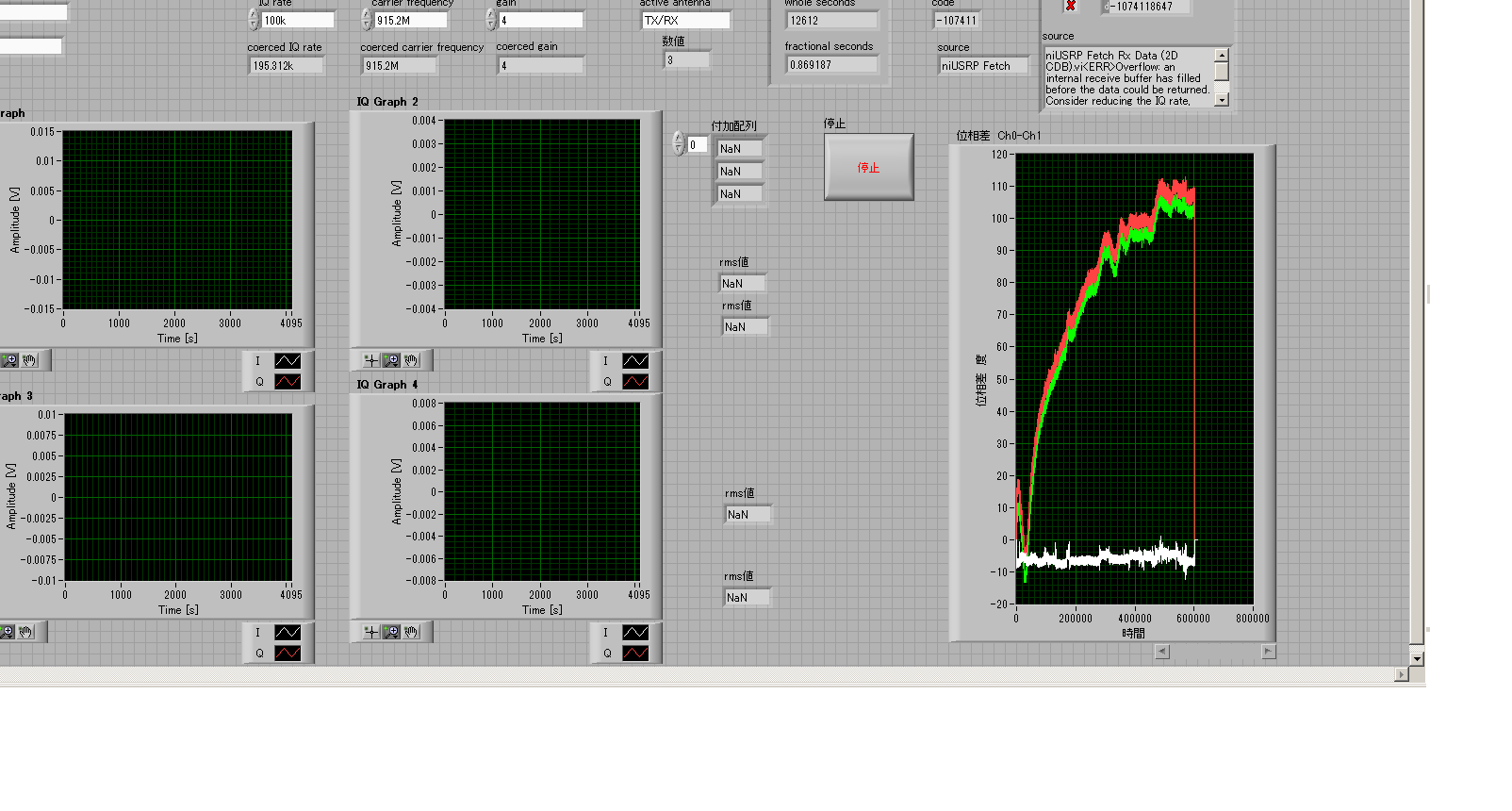
Right end indicates derivative of phase offset for 200 minutes; white line is ch2 - ch1, red line is ch3 - ch1, green line is ch1 - ch4.
It seems that each pair MIMO has kept the same phase offset but pairs diffreent MIMO.
Is - this results?
Here's the configulation in LabVIEW Block diagram.
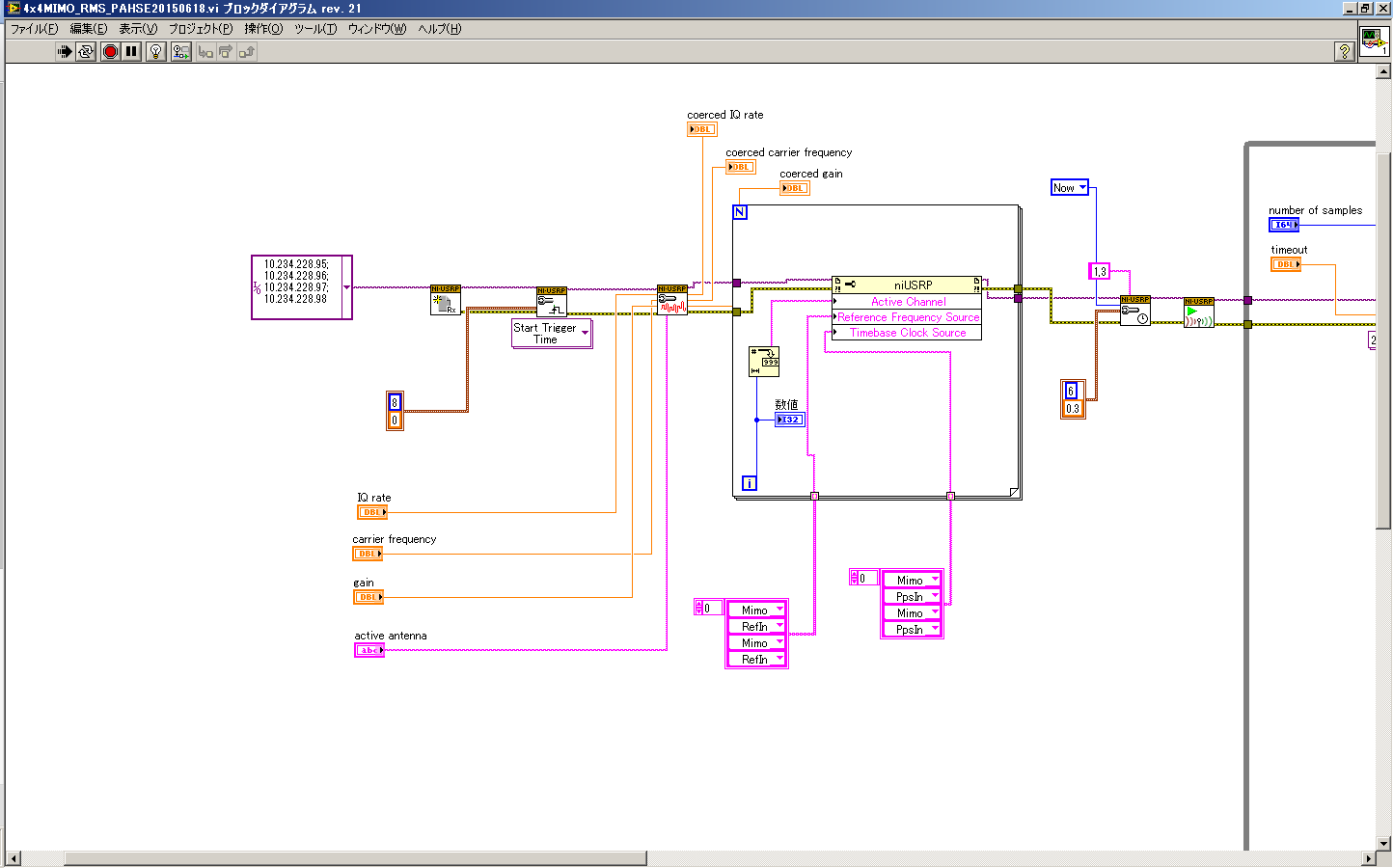
I tried like and found my phase USPR N210 WBX offset remains constant.
My vi can be a bad thing.
Sorry for the bad because of my misunderstanding infromation display.
After fixing my mistakes of Vi, I'll show them.
Tags: NI Software
Similar Questions
-
Hello world!
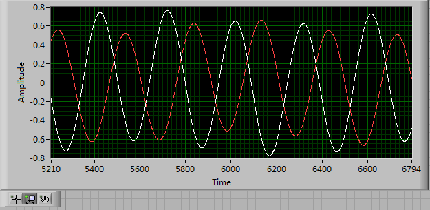
First of all, I use a USRP as a transmitter to emit a sine wave (the signal is exp(j2*pi*f*t)), and then I use the external clock to synchronize the two USRPs (Ref as PPS in are connected to the clock) as receivers. Receivers are in sync, and they are at the same distance from the transmitter, I thought that the signal they receive should have a nearly the same phase. However, in practice, the phase shift is big enough, and this problem really confuses me.
It's the received signals of 2 receivers.
Yes. What you observe is expected.
Near the bottof of this document read the area 'alignment Phase vs Phase coherence '.
http://www.NI.com/white-paper/14311/en/
And also, for the alignment phase, see the following 'Angle of arrival detection with NI USRP '.
https://decibel.NI.com/content/docs/doc-25716
Erik
-
: HP Quicktouch on screen has stopped working, computer will not remain once I connect.
So looking at the forums and everywhere on the internet, I know this problem starts because of an update that I installed it. But what I'm trying to understand why my computer will not remain after that window opens after I connect, because it restarts whenever I log in. I became extremely frustrated with this issue and I really don't know what to do. of course, there is the system restore, but that work? I can't find quicktouch in my list of programs to uninstall in safe mode, because this is the only mode that will allow me to stay very long. so if anyone has the answer please help me, it's super frustrating.
Hi cavalierfanatic247,
Thank you for using the Microsoft answers Forum.
Start on Safe Mode desktop.
Remove the update that caused the broadcast of programs and features in Control Panel by clicking View installed updates.
If you are not able to remove the update, use the utility window cleaning to remove the update. See the link below:
http://support.Microsoft.com/kb/290301If the steps above did not fix the problem, try to restore the system to a previous point before windows update when it worked fine.
To restore the operating system to an earlier point in time, follow these steps:
Click Start, type system restore in the search box, and then click System Restore in the list programs. If you are prompted for an administrator password or a confirmation, type your password or click on continue.
In the System Restore dialog box, click on choose another restore point and then click Next.
In the list of restore points, click a restore point created before you started having the problem, and then click Next.
You have an Essentials and HP drivers disk?
If the system restore is not enough, you can use the HP Essentials and the disk drivers to uninstall and reinstall the quick key.
Click Finish.
You can see the link below for more information:
http://support.Microsoft.com/kb/936212
I hope that this will really help you, good luck.
Kind regards
Manasa P-Microsoft Support -
Align the two signals and measure the Phase Shift
Hello
I do an experiment in which I use the NI USB-6221 DAQ card. The jury is able to make 250 k samples/second. I want to measure two voltages in a circuit and find the phase shift between them at frequencies between 1 and 10000. First I ouputted a wave sinusoidal frequency variable through the Commission and applied to a test circuit. Then I used the Board to measure the two tensions consecutively (thus reducing the maximum sampling frequency at 125 k). I used the signals align VI and measured the two phases and then calculates the phase shift (VI attached in Phase 1). It worked well for the test circuit I built in which the phase shift went way logarithmique.20 degrees ~84.5 degrees and then stabilized. At frequencies above 5 000 Hz phase shift must have remained constant, but it varies more or less 1 degree. When the phase shift is 84.5 degrees, present a degree of variability is not particularly explicit. When I asked my program on the circuit that I really wanted to measure, the phase shift went from-. 5 degrees up to about 1.2 degrees. The change in the values of phase shift at high frequencies (> 3000) was environ.2 degrees. Given the small phase shift, this variation is unacceptable. Now I tried to use a sequence to each blood individually (increase the maximum sampling frequency to 250 k) and then align the two signals and measure the phase of each shift. When I use align it and re - sample Express VI to realign the two signals, I get the message "error 20333 analysis: cannot align two waveforms with dt even if their samples are not clocked in phase." Is it possible to align two signals I describe here? I enclose the new VI as Phase 2
Matthew,
I think I have an idea for at least part of the problem.
I took your program data and deleted stuff DAQ. I have converted the Signal on the chart control and looked then what was going on with the signal analysis.
The output of the Waveforms.vi line has two waveforms, like the entry. However, arrays of Y in the two waveforms are empty! It does not generate an error. After some head scratching, reading the help files and try things out, that's what I think is happening: the time t0 two input signals are 1,031 seconds apart. Since the wavefoms contains 1,000 seconds of data, there is no overlap and may not align them.
I changed the t0 on two waveforms are the same, and it lines up. The number of items in the tables is reduced by one. Then I increased the t0 of 0.1 seconds on the first element. The output had both greater than the entry by dt t0 t0 and the size of the arrays was 224998. Reversing the t0 two elements shifts the phase in the opposite direction.
What that tells me, is that you can not reliably align two waveforms which do not overlap.
I suggest that you go to 2-channel data acquisition and that it accept the reduced sample rate. You won't get the resolution you want, but you should be able to tell if something important happens.
You may be able to improve the equivalent resolution by taking multiple steps with a slight phase shift. This is similar to the way that old oscilloscopes of sampling (analog) worked. Take a series of measures with the signal you are currently using. The make enough average to minimize changes due to noise. Then pass the phase of the signal of excitement to an amount that is smaller than the resolution of phase of sampling rate and repeat the measurements. Recall that I calculated that for a 5 kHz signal sampled at 125kHz, you get a sample every 14.4 degrees. If shift you the phase of 1 degree (to the point/mathematical simulation), you get a different set of samples for excitement. They are always separated by 14.4 degrees. Take another series of measures. Transfer phase another degree and repeat. As long as your sampling clocks are stable enough so that frequency does not drift significantly (and it shouldn't with your equipment), you should be able to get near resolution of what you need. The trade-off is that you need to perform more measurements and may need to keep track of the phase shifts between the various measures.
Lynn
-
Problem with connecting to USRP N210
Hello
I have some connection to the USRP N210 device problems. I have 2 in my possession at this moment and I use a switch to connect the two to my laptop. Thus, 1 has a IP address of 192.168.10.2 and the other has 192.168.10.3. I can connect however only la.2.3 device and not a. Even when I plug unit only 1 to my laptop (without the switch), I still can only connect to the peripherique.3 and not la.2 one.
.2 device appears in the application of devices to find however and I can ping to it. Only when I try to connect to the device through Labview, I always get an error.
You have any ideas about what could go wrong here?
My specifications:
LabVIEW 2012 (32 bit) + Modulation toolkit + OR USRP API
Windows 7
Hello!
Two quick suggestions to try:
1. is the firmware update for the FPGA and EEPROM.
2. What is the error you get in LabVIEW? (Explanation of text and number)Erik
-
Phase Shift Key: Modulation Toolkit
I am trying to simulate a phase shift key, I have followed an example of OR. the example worked fine and I used the same code but does not work my didi. The number of symbol is not correct.
I have attached the VI, I could not know what the problem was. The chart of the constellation should remain constant, rather than moving and the number of symbol in the chart must be equal to the symbol on the control.
Thanks for any help.
Hello ade77
Thanks for your post. It seems that your Eb/NO (10 dB) value is not high enough to get the right number of symbols in the right place. Try to increase this number and see if that helps. See the screenshot of your attached code.
Let us know if this helps!
See you soon!
Corby_B
http://www.NI.com/support
-
Using OSX El captain on a desktop iMac. iPhoto 9.6.1
I tried to buy my book - this box appears - TEXT by DEFAULT - your book seems to have default text that has not been modified. Printed books will not include this text. Does this mean that all my text will not print?
I've been twice now and change the text of Bradley Hand to the Blackboard to Helvetica Neue - which seemed to be the default. Message remains displayed. I don't know what else to do. This is my third book over the years, but the first with this problem. Can someone advise please?
Thank you Davina
It is not a problem of fonts. It is the problem of the sample text entered by the models.
The error message means that there is a text field in your book which is still on show at the text included by the model, and you will need to replace this text with your text. This textfield might be hidden behind a picture.
If you create a preview of the book, such default text is omitted. Have you compared the preview of what you see in iPhoto? Text that shows in iPhoto, but not in the preview will be such default text.
For example, the section 'Topic of this book' on the flap back in some themes is a default text that should be replaced by your own legend:

-
My iPod 5th generation is stuck by resetting the settings and I tried holding the power and the "home" button but has just the same. Also, I tried to sync it upward, so I tunes but it has not been recognized and I can't answer on my iPod. Help, please!
Try the remaining shares of:
- iOS: do not respond or does not light
-Also try DFU mode recovery mode post-test
How to put iPod touch / iPhone in DFU "Karthik doodles."
-If failed and that you cannot completely turn completely the iOS device, leave the battery to drain completely. After loading a hour repeat the foregoing.
-Try a different cable
-Try on another computer
S ' there is still not successful that usually indicates a hardware problem and an appointment at an Apple store Genius Bar is in order.
-
USRP N210 connect through SWITCH GIGABIT
Hello
A quick question to make it easier to work.
Now, I use 2 computers to the internet and work with the USRP.Is it possible to connect my computer AND usrp to a gigabit switch so I can use internet and at the same time the USRP?
The subnet I receive is 10.67.49.1, so I give 10.67.49.2 my USRP.
My computer is assigned a random ip address in the DHCP-here beach. 137, but I can't see the USRP (not in the cmd > arp - a, not in of usrp config util). Even when I change the IP of my computer to: 10.67.49.3 it does not work...But when I connect the usrp to my computer and use static IP address, it recognize...? Or is it just not possible...?
USRP n210
Windows 7Thanks in advance
-
phase shifted PWM with Ni 9401 and Crio
Hello
Do you have an idea of pwm shifted 180 degrees?
(duty cycle frequency and variable difficulty)
I tried a design, but it seems in the graphics design works on the realtime.vi but it does not work with the fpga.
Graphic output pwm FPGA are distinguished by the real time as you can see in the pictures.
On the other hand, VI Fpga produce two pwm, as seen in the oscilloscope when the fpga VI runs.
However, there is no phase shift between the PWM waves.
It is a part of my thesis, but I'm stuck in this problem, so I need assistance on your part.Thank you.
Best regards;
My hardware:
cRIO-9024 and cRIO-9118 chassis
NOR-9223, 9263 - nor, nor-9401, or-9474
two nor-9225 and nor-9227
Hi Maurice
Thank you for your help.
Yes I want to that they will be moved with the right variable and 10 kHz. I put 49% maximum duty.
I put the output into the same output block.
Square wave generator does not accept 'loop' while.
I have attached a simple FPGA project file. Could you please tell me what is my fault?
The resulting Pwm frequency is 10 kHz, the only problem is always the shifters.
So, I always need assistance.
-
Source a current Sine using USRP N210 with Labview
Hello
I use USRP N210 with boards LFTX/RX for communication (electromagnetic Induction) cable and programming using LabVIEW and downloaded the drivers. I need to order the USRP to send a signal sine of 1 MHz through the barbed wire. I used the "Sine simulation block", but I'm not sure the block to which it must be connected to. Please let me know the steps or the blocks/screws that can be useful.
Thank you.
Hi Julie,.
I think you need to use the open niusrp and log screw
You don't need to use the configuration VI signal because I think that you can not set the frequency of the carrier on the Remora LFTX and LFRX.
I think you can use the sinus blocks of generation as shown in the picture as an attachment.
Thank you.
-
Hi all
I'm doing a two-way-going using the USRP n210. To be able to do that, I will need to know the exact time that samples have been sent and the time that I have received back.
Trying to implement that I want to use 2 USRPs linked together.
(USRP HAS) (USRP B)
TX<----------------->
rx -----------------> txFor the porpuses first test, I used a single USRP linking the RX and TX together. With the help of a simple flow in the RRB graph I out a pulse (using the vector source) and at the same time, I have everything from the entrance of the USRP stored in a file (using the file sink block). For comparison, I also used a file sink block in the output.
Testing again the difference between when I starts the code and the time the impulse arrives at the RX looks like that there is a kind of random delay. The difference between the send and receive in return the pulse fluctuates around 8000 ~ 10000 samples. Because I use a single USRP with RX and TX interconnected I though that this time limit should be almost zero.
There's a better way to implement what I can get better accuracy in the timestamp?
One solution that has helped me to solve my problem was using the following code in the code generated by the companion of GNU python:
now = self.uhd_usrp_sink_0.get_time_now (#Store) the real time of the FPGA
Self.uhd_usrp_source_0.set_start_time (UHD.time_spec_t (1) + now) #Set the source to start 1 second after the real time of the FPGA
Self.uhd_usrp_sink_0.set_start_time (UHD.time_spec_t (1) + now) #Set the sink to start 1 second after the real time of the FPGAIn this way both tx and rx, will begin at the same time.
-
Phase shift a channel and display
Hello
I'm working on a project for which I have to display the I-Q constellation plot and normalize the data to fit a circle of unit RADIUS.
I'm able to do this, but the problem is sometimes the signal in one of the channels is very low and therefore, the plot moves close to the routes (Please find attached the file, this is the best position, if a channel has a weak signal, the movements from point to one of the axes). When this happens, I want to add a phase shift of the signal (45 degrees and multiples of it) to bring to the back for the best position. I tried to use the extracted tone vi phase go, add 45 degrees, but how to rebuild the spirit of the new signal phase?
Can someone help me please?
Thank you very much
Despres
-
variable phase shift between two analog output signals
Hey! I would drive two different piezo elements with an sine - / square signals and have a phase shifted output signals. After some trail and error, I was able to get a second analog output on my card PCI-6221 (using LabView 8.2) also allowed me to have different amplitudes for both signals. However, I could not output signal having a frequency different and most importantly to my request to have one of the signals variably shifted phase.
Thanks for the very useful suggestion. I have attached the file .vi installation I've run so far.
Hello!
A way to generate waveforms is using the analog waveform Toolbox. I created an example VI that is attached and that shows you a way to use the base generating function VI. I saved for LabVIEW 8.2.
I hope this helps!
-
Medium need to return false if a value has not yet been written.
I am a new user of labVIEW here looking for a way to return false if the value has not yet been written.
I am using the "select" tool to swap between values early enough in my simulation. However, it requires data that has not happened yet, so I need something that is waiting for the value to write.
Is it possible to use a while loop to wait until TRUE or FALSE (instead of NULL) has been written and then change the frequency?
All instances of data in LabVIEW (controls, terminals, constants, shift registers etc.) have a value, there is no concept of NULL.
A Boolean control, before write you, will be its default value (probably false). A string will be empty (but not NULL, it is always valid). A digital will be zero, a reference is not valid (possibly equivalent to NULL, but this terminology is not used.)
Can you describe your needs more detail, I don't understand what you need to do.
If you want to wait for a change in value (Boolean to change true), then survey (read several times) from the Terminal command in a while loop with it connected directly to the terminal of condiitional. Its default value of False will cause the while loop loop continuously until the value is set to True. I would advise to insert a short wait inside the loop so that it hoggig a CPU.

Maybe you are looking for
-
Hi, today I was walking and using my iPhone 5 c and I dropped to about waist high and when I picked it up it was black. I tried to turn it on and it was black. So, I turned on my ringtone and nothing happened, so I've done that I tried to do a hard r
-
I tried the recommended two solutions to replace but none works. Firefox was slowly turning last night so I decided to update it. Did not help. Downloaded again, but now can't access it at all. I'm on a Mac using 10.9.5.
-
HP Pavilion a1640n: install a new nVidia video card
I just bought a GeForce 9400 GT from nVidia video card to upgrade my HP Pavilion a1640n running Windows XP SP3. The a1640n has integrated the video and says nVidia user guides: "If your motherboard has integrated video card integrated, you may need
-
10-2101 Tablet HP - try to get the product manual
I just bought this tablet and a few questions - I thought I could control google voice to send emails to me, but it won't work. Thought maybe the manual/product manual might help me, but I'm having a difficult time finding online. (Not much came wi
-
I know this may seem a stuid question but I just you'd be grateful if someone could help me