Misfortunes of connector pane
My guard re-failing itself to a connector pane layout unwanted 6446, possibly after looking at someone else's code.
I tried to play with the LabVIEW.ini keys and I searched on the tools > Options you are looking for something related, but whenever LabVIEW is restarted, the connector pane returned to 6446.
Am I missing something?
Tags: NI Software
Similar Questions
-
LabVIEW allways modifies the default connector pane
Somehow my default connector pane is always reset zo 6x4x4x6 (instead of the normal 4x2x2x4). No idea how this happens.
I can reset it by deleting the line
defaultConPane =...
in LabVIEW.ini (so LabVIEW is running).
But when you restart LabVIEW (or when you open a project containing no screws?) the line is rewritten.
Does anyone know this problem (in LabVIEW 12)?
(The configuration ini directive is described in the following article.
http://digital.NI.com/public.nsf/allkb/279F064F0688C114862570900057678C
It comes to LabVIEW 8.0, but it still works in LabVIEW 12.)
You use G # by chance? I think remember that it changes the default connector 6446 pane.
-
Get the reference to control of the connector pane
I'm trying to get a reference to a control associated with a specific index in the connector pane. I see that there is a method to assign control to a terminal, but not get control of a terminal-specific. I know that I can enumerate all the controls in the connector pane, but it doesn't specifically tell me where they are.
Edit: I see, there are private methods to get and set properties that can have this info, but because they are undocumented, and they are properties of a VI that is binary, I can't bone.
When you read the Controls property of [class ConnectorPane], he puts back them to you in the order of terminal. There is a VI in the examples folder that shows you the order for each connector component model (visually). I don't have LabVIEW in front of me at the moment, but it should be examples\Application part Scripting\Connector Control\VI, or something like that.
-
Subvi value not updated when it is connected to the connector pane
I have a legacy program that computes a frequency when a value changes of sensor (falling edge essentially), and I'm trying to convert the logic to a Subvi, so I can use it for 44 other sensors. The program first used a large number of property value node, I discovered is not good for subVis. I converted them to local variables, but I still have questions.
As soon as I connect something to the output pane that closes the update value question. If I remove the connection in the connector pane, it works fine.
a picture of the block diagram is attached. I tried to connect Freq and frequency of output to the connector pane, as soon as I connect it to the component connector to work properly to date do not at all.
The VI is configured as non-reentrant.
Thank you
-
Could not load the connector pane
Has anyone else had this error before? I asked tech support, but they had not seen anything like that either.
System:
Windows 7 Professional (64-bit), LV2010 (10.0f4 v, 32 bit)
The repro steps:
(1) create a new VI (any method)
(2) right-click on the icon and select 'display the connector '.
Expected result:
Connector pane appears
Actual results:
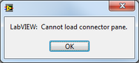
Error message - "LabVIEW: cannot load the component connector.
Workaround solution:
Click OK in the error message. The connector pane then charge and everything works fine.
This happens only the first time that I open the component connector on a VI; It does not happen after that I have opened (even after the backup, etc.). Technical support had me try the f4 patch, reinstall/repair of LV2010, and I even made a compilation of mass for good measure. It is not a real problem (I just click OK on the error and go about my business), but I'm curious to see if anyone has seen this kind of behaviour before.
-Daniel
So if you have an archaic line in your file LabView.ini (maybe since way back in the days 6/7/8.x and it is simply copied to after each upgrade, then copied on new computers) and it looks like this:
defaultConPane = 4185

Then you could try to load a connector component that does not exist. It should perhaps have been 4815, or something else. In any case, delete said line and everything is fine.
http://digital.NI.com/public.nsf/allkb/279F064F0688C114862570900057678C
-
white connector pane programmatically set
OK, I found this:
> To use the call by reference for the screw with the different, unknown Connector components,.
> methods Get/SetControlValue to set the inputs & outputs instead of wiring
> to the call by Ref-connector pane; and force the screws comply with the 'white '.
> connector pane (it can be set programmatically).
I am get and set values of control very well both the vi which is called by reference has the same connector model and all terminals are disconnected. Any body know how to get to the second part of this information (IE disconnect all terminals by programming)?
If you define the model of vi referenced which would be even more chic or better yet, read the model and be able to create a strict typed reference (knowing that I prefer not to worry the exact model / connections of the vi, I call you).
You must use the server method VI "Run", instead of the call by reference. The
only reason to use the call by reference, is to use the connector pane.
If you do not use this feature, use the Run method.Waiting set to true and the Ref. autodispose also to true, and it doesn't
just like a call to reference, without the functionality of the component.Kind regards
Wiebe.
-
connectors showing vertically on the standard connector pane
Anyone know why my terminals of the connector here are the vertical for the cluster?

Is the link on the left indicator and the connection on the right control?
-
Why the connector pane displays a different connector for lvclass?
Picture is worth 2000 words...
What is the special problem with the connectors on the left & right superiors?
I have other lvclasses, but they do not have the points X shaped...

Those who are marked as dynamic connections distribution (take a look on where you would be required). An entry from JJ means that it is a VI that is designed to be substituted dynamically at run time according to the type of class actually present on the wire.
-
dynamic cluster in Subvi connector pane
Hello
I would write a Subvi, which takes a dynamic cluster, accesses his property of [control] and acting on the results. I don't know if this is possible, or at least have not thought a viable option. If anyone has any ideas, I like to hear them. Let me know if I have defined my problem well enough.
This is possible, do a 'Variant' type connector
With the OpenG LVData toolset , you can get all the information you need.
Tone
-
That means the following message from VI Analyzer: "part of connector of this VI is not a part of the connector that is specified by the user."?
The VI it references has 4 connections: 2 in. and 2 outputs. He was selected from a template.
Everywhere where the VI that it references is used is relinked and properly connected.
While it has been warned?
As it says, this is just a warning.
Many programmers standardize on a small selection of models of connector. VI Analyzer will tell you if a different connector pane is used. One of your screws apparently uses a connector part 2 x 2, which is not used very often. (Example (1) it must be changed if you need connectors later, (2) it does not match the gap-type-in and error-out lower terminals, (3) if it is mounted in series with subVIs most popular models, the son will have elbows and things not the line-up, etc..)
Two choices:
- If you are really in love with the part of connector 2 x 2, add it to the configuration of the parser as a reason accepted.
- Stick to a more standardized connector component, even if not all the connectors are currently used.
-
How can I identify connector control or indicator?
Hello
I can't see the wood for the trees. When I want to see what connector terminal is connected to a particular/indicator control, I have to click on each connector in the connection pane until the command/idicator is highlighted. Is there a faster way?
pgaastra wrote:
Hi Darin,
Do you mean using context-sensitive help by placing the cursor on the icon of the VI in the block diagram of VI calling the VI I'm editing. If so, that means just a few more clicks to get the diagram of the VI calling visible.
If you have the contextual help window open and the cursor over the connector pane you see all connections (unless you play with optional connections and display the window HP options). It might be useful if the CH window gave you the ability to view the icon or the ConPane.
In fact, I wrote my own Publisher Conector pane and my eyes and my carpals tunnels have never been happier.
-
Wiring of connectors in LabVIEW 2011 problems
I've just been 'bitten again"by a wiring problem with a connector for a VI in LabVIEW 2011 (I've not seen this behavior in any previous version of LabVIEW to 7.0).
The question is this. I (or one of my colleagues, who also noted it), run LabVIEW 2011 (August 2011 release), 32 - bit, Windows 7, 64-bit systems. I have create a VI using the usual 4-2-2-4 connector of mires and connect the appropriate connector. I save the VI, then drop it on a block diagram to use.
In another variation of this problem, the VI has fallen don't watch any connector or, if used to 'replace' an existing wired in VI with the same model of connector, "break" all the sons (because it has no connector when dropped on the diagram). Reopen and reconsider the VI show that, indeed, the connectors are wired, but when I use the VI, the connector wiring is absent (the VI dropped watch without connectors).
In the second variant, all right, the connectors appear as expected. But I then decide to move a connector. I have open the VI to edit, make a cut of this Terminal and rewire to its new location. The connector pane presents the new model. But when I drop the VI on a block diagram, the connector is in its original location.
Restart LabVIEW, indeed restart the PC, does not change. The only way to 'fix' this is to disconnect all terminals and a reconnect them. A nuisance, to say the least, but also an obvious bug.
Has anyone else seen elsewhere? I sent to OR, but it would be useful to know 'is it just me?' or not. In my defense, I've seen this problem on several computers, all win 7/LabVIEW 2011. I've also seen this with several LabVIEW projects.
I've attached a file with such a VI "buggy". When you open it, you will see that the 'Length' indicator is wired to the top of the connector set page. When I drop this VI on a new VI, however, the connector indicates coming out from the bottom!
BS
I was told by an engineer NOR that this problem (a) is real and (b) has been fixed in SP1 release (spring) 2011 LabVIEW. I have not had a chance to check this point, but (the trusting soul that I am), I consider that this problem has been a "Bug in LabVIEW 2011 that has been fixed in the SP1 Release"and therefore, I am prepared to mark this "resolved".
-
under condition of read/write terminals on the side of the connector (basic training 3)
Hello
During my practice towards the review of the CLD, I examine the Core 3 online training material too. I just read a few tips of 'best practices' on the forum, for example this post:
It should be noted, that we should not use terminals (which are on the connector pane) to the inside of while loop or condition of the structure. Neither control, nor indicators (read/write terminals): "terminals conditionally read or written on the side of the connector are BAD!"
I can find many examples in the online training materials, when the indicators and controls are placed inside while loop and the case of structures in a Subvi.
I guess I should not do this during my review of the CLD, as they will run benchmark on my project? Should not be the core training materials updated some time? Or it's just not too important to have terminals on the outside? I would lose points during the CLD Exam my project as in the Core 3 screws?
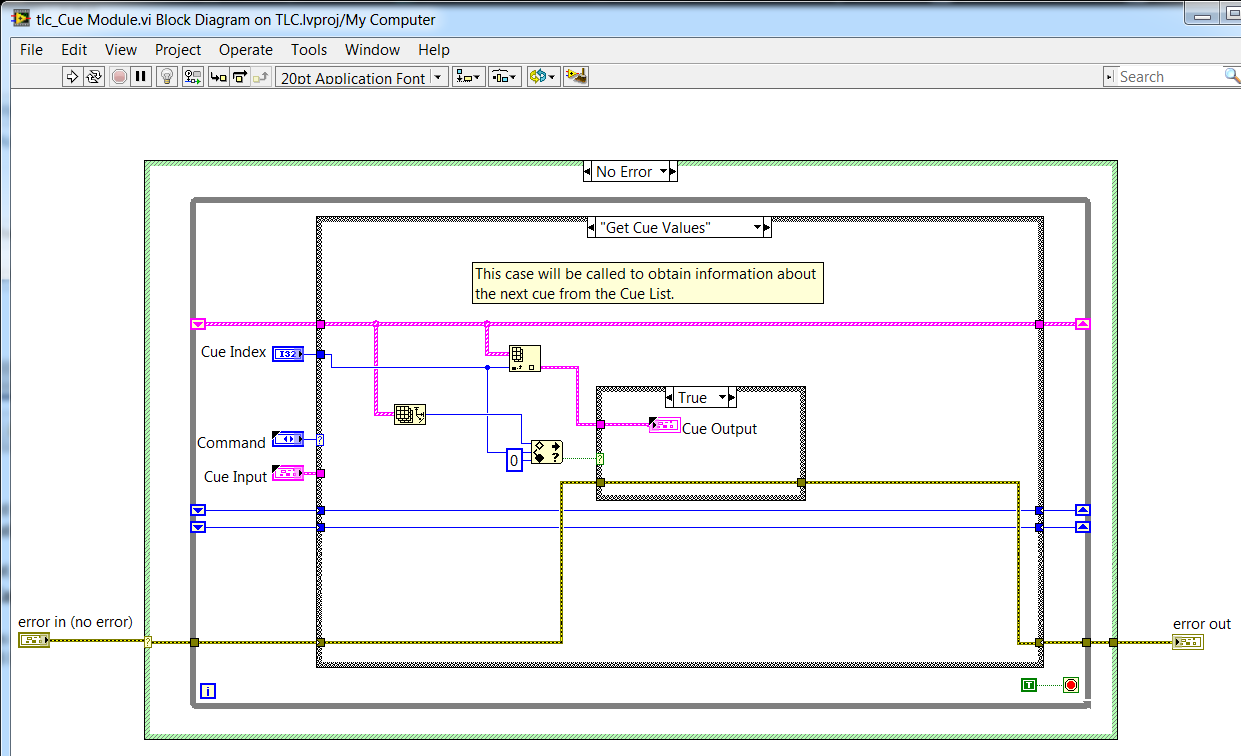
example 1: Core 3, exercise 4-6 design of an error-handling strategy:
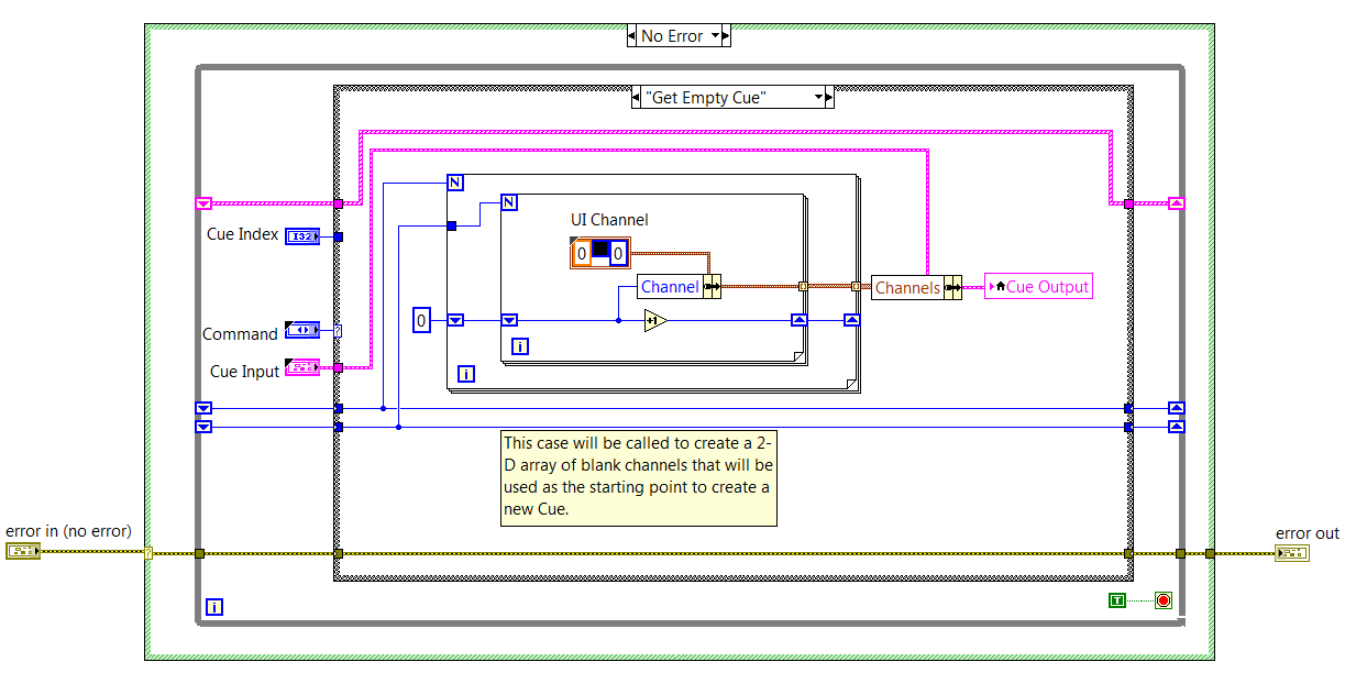
EDIT:
What's even more ugly in this project, is that, in the case of 'Get empty Cue', the Cue output indicator is updated via a local variable, because the indicator is not accessible via 'outside ': wire
Nice catch on the training material. that the application would take an if subject to a review of the CLD test graders.
As noted in the nugget: sentencing of perfomance for conditionally reached terminals is a function of the size of the data. So, it is sometimes acceptable for simple data. The larger point being to learn about compromise and make the right choice for your code.
Preping for the CLD on other means of hand knowing that VI Analyzer will run on your project. Like any other code review you walk in - know the guidelines for the review and code to ' review ' as well as 'reply spec.'
I've not seen an instance where an example of shipping (2013 and later versions) would fail this test VIA (there are a few screws deep inside the vi.lib which can date back to before the adoption of this recommendation from style)
-
Discover the part of a node connector
Hello community,
a search on google has failed me so this is:
Is it possible to find the only ot what the part of a node connector looks like?
Nodes in LabVIEW are not screws and therefore cannot be opened to inspect the connector pane.
My intention is to create a sub vi to replace a certain node (in this case ' dialogue of a button'). I hope that if I could match the connector pane I might actually use the function replace on multiple instances of the node without having to fix the wiring manually.
Any help would be appreciated.
First of all, I don't know what you want to achieve.
However, you can click with the right button on all nodes and select the visible items > terminals.
A second point is to activate Scripting (LV Options > VI Server) with the subsequent 'display VI Scripting of additional information in the context-sensitive Help window"to see the command script of the terminals of a node.
Maybe it's the information you need. If no, please describe the use cases in other words who are hopefully more understandable...
Norbert
-
Hi all
Could someone enlighten me please, what does this comment on the value of the ADC
"Terminals on component connector not on the block diagram of higher level of control.
This means that some terminals is hidden within certain structures of the case and does not show not not the diagram without going into the structures of the case or by 'higher level block diagram', it means
main.VI and main.vi controls must also be connected to the connector pane?
Thank you
K.Waris
On the one hand, this means that they run on your screws VI Analyzer, since it is a warning in extenso you receive. This means simply a terminal which is connected to the ConPane is not on the top level diagram, IE. within a structure of housing.
As to why he is often not a good idea to do that read this classic thread:
http://forums.NI.com/T5/LabVIEW/case-structure-parameter-efficiency/m-p/382516#M191622
Maybe you are looking for
-
Why my iPhone hidden FaceTime App when I'm in Saudi Arabia
Why my iPhone hidden FaceTime App when I'm in Saudi Arabia and UNITED Arab Emirates &?
-
Hello I use jpg under vi reading and take the image data after I decimate the table, three vetors of each of each corresponding to R, G, and B are created. Calculate the average value of R in the manner mentioned in my attached program and I find tw
-
Office Pavilion 500-119: adding an SSD 240gig
Hi, this is my first post. I want to add an SSD, I am looking at a Kingston 240 gig ssdnow v300 upgrade kit. I still run the operating system with the already hard drive of 1 t. So the additional SSD will be an extra disk to run VSTs for piano who ne
-
I get the BSOD every once in a while during a variety of programs. I've updated all my drivers. I use bluescreenview watching dump files and that's what I have. A problem has been detected and Windows has been shut down to avoid damage on your comput
-
What just happened to my Photos app? I need help please. :(
A bit complicated, but totally mind boggling, and I need your help. This all started when I'm about to see my photos. I clicked on the Start menu, and then clicked on the Photos app. He just opened indeed, but all of a sudden it's just freezes and I