Models and simulation of collage/combination
Is it possible to paste or import a software simulation that has already been completed as a project in another project that was created by using a project template? I tried just copy / paste, but it did not work. Any help is appreciated.
You can copy and paste slides between the projects, but to ensure that they have the same resolution. A model has nothing to do with it, you copy and paste between cptx-projects. Or do you mean that you are using a model (cptl) and a cptx project, which is a simulation software?
Tags: Adobe Captivate
Similar Questions
-
Modeling and Simulation occur error
I have established a model APEX PA78, but the simulation reports any error, please help me!
View report worksheet is followed:
-Audit netlist SPICE to PA78 - 2010-01-28 20:12-
Error of SPICE Netlist in schematic RefDes 'u2', item 'xu2': unexpected '15' found subckt - too many nodes or missing name value parameter instance online.Error of SPICE Netlist in schematic RefDes 'u2', '
' element: due to errors, the instance subckt "xu2" has been omitted from the simulation Error of SPICE Netlist in schematic RefDes "u1", item 'xu1': unexpected '1' found subckt - too many nodes or missing name value parameter instance online.
Error of SPICE Netlist in schematic RefDes "u1", "
" element: due to errors, the instance subckt 'xu1' has been omitted from the simulation = SPICE Netlist verification completed, 4 error (s), 0 warning (s) =.
---------------------------------------------------------------------------------------------------
The accessory includes three files, they are:
PA78. TXT is the BERKELEY SPICE on PA78 model of
http://Apex.Cirrus.com/en/products/Apex/design_software.html
PA78U_B.PDF of page on PA78 of
http://Apex.Cirrus.com/en/products/Pro/detail/P1163.html
PA78. MS10 is a configuration of bridge-connected, but PA78 itself do not work a simulation.
Hello
I'll expand a bit what Angela said on the. ENDS and then try to clear up the pins.
The SPICE model that you use for the PA78 includes several subcircuits and models. Best practices for creating a component in Multisim are having one. SUBCKT or. MODEL for each component. The point of this is to ensure that the additional models or models contained so that they do not interfere with each other in the final netlist. The best way to solve this problem is to move the. ENDS during the main subcircuit until the end of the complete draft - so, instead of simply add the. ENDS at the end, you must also remove the first. END of line in the file. For this circuit, you probably don't need to do it, however in general, it's a good idea to do by making a component like this.
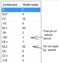
With respect to the pins, step 6 of the component wizard asking you order the pins will be used in the model. The (original) model that you have only 10 knots, so it isn't a problem if you have only 10 pins there. If you have 12 pins on your symbol, and only 10 model nodes, then you score just two unused pins as "NC"(vous pouvez également ajouter deux broches"fausses"pour le.) ". SUBCKT which is what you did, but you have not).
For the rest of the pins, see the. SUBCKT line and comments just ahead of him:
* PINOUT ORDER +IN -IN IL OUT +VS -VS CR+ CC+ CR- CC-* PINOUT ORDER 7 6 1 2 12 4 8 11 10 3.SUBCKT PA78 7 6 1 2 12 4 8 11 10 3
Comments indicating the order of broaching tell you the order in which the terminals must be indicated when you use the PA78. SUBCKT. As you can see on the. Line SUBCKT and comments, even if IT is pin 1 on the component, it should actually be listed third when you use the. SUBCKT. It's asking you to step 6 in the component wizard. Step 6 allows you to specify the order in which to use the pins to Multisim. The comment you indicates that + is the model node 1, - IN is model node 2, IT is the model node 3, etc., and then you say Multisim by setting the number of nodes of model
Hope that helps!
-
With the help of control and simulation module; e to get the time the MISO model Manager
Hello
Please can someone show me how to find the response time of the system below using the module control and simulation?
(y (k) - 1,7407 y (k-1) + 0.6236y (k-2) + 0.1782y (k-3)) =-0.0932 u(k-1) + e (k)
where there is out, u came and e is a white noise.
I tried to enter the CD construct MIMO model, then connect it to CD response time. * s vi.
But what I really need to enter the model coeffs every time? and I still don't see the answer!
Help, please...
Kind regards
ruser
Hello
you have the correct image... I used the Toolbox ID sys (Assistant)... to estimate the system model...
and I tried all week last get the model of my system in labview for use the control on this module.
Alhamdulillah...
I ended up doing... I saved the template to a file from the Toolbox id sys... (my model is in discrete form) then I loaded it in labview using load file pattern...
so now I in labview...
now for control parts...
 ..
..Thank you again...
ruser.
-
Control and simulation and data acquisition
Hello
I am applying to motor control in Labview. I'm sampling speed from DC engine in real time through an acquisition of data. (my sampling time is 1000 samples per second)
Then wrap speed as input to a Simulation (simulation and design of the order) and inside the loop simulation, I have a PID controller. The PID has the actual speed of the engine for the acquisition of data and the engine reference speed as input.
Reference engine speed comes from the generator of signals (control design and simulation-Simulation) and is a waveform.
My step in the engine size is 1000.
I am running this application real-time and drawing the reference signal and the motor real signals. I run into several problems with regard to the calendar.
1. when I change the size of the step of the simulation loop, the frequency of squares of reference also seems to change. For example. What step size = 1000, duration of pulse = 1 s. What step size = 100, pulse width = 0.1. (My pulse frequency is 1 Hz, Simulation clock - 10 kHz). How step size can affect the pulse width.
2. can you explain the relationship between the DAQ, the Simulation step size loop sampling time, Loop Simulation period.
3. If I want to collect different sets of data using sampling different hours, it's OK to change the sampling DAQ time without changing the size of the step of the simulation.
Would also like to emphasize that the DAQmx calendar under sample clock mode is placed in front of the simulation loop and the output is connected to the loop simulation.
Appreciate any help.
Hello
Maybe some screenshots of your code would help. Furthermore, what you have read your samples together with your DAQ screws?
(1) If you have a waveform, the output is specified as:
For example, if you change the size of the step of the simulation loop, you change the simulation time which are introduced into the signal generator and affecting the waveform that you see if you do not have a size quite small step to characterize the waveform that you generate.
(2) sampling DAQ rate is the speed at which samples are taken on the acquisition of card data itself. The size of the simulation step, help. "Specifies the interval between the time when the ODE Solver evaluates the model and updates the results of the model, in a few seconds." Simulation loop, still using, "Indicates the amount of time that elapses between two subsequent iterations of the loop of control & Simulation.". " "Step size determine the value of t that is introduced to the functions you use in the loop simulation while the loop simulation period controls simply to how fast you change the following t value. The sampling rate of DAQ hardware is a clock of completely separate hardware controlling the analogue-digital on the DAQ card converter so that you can get a deterministic dt between the samples being acquired.
(3) you can change the schedule for the acquisition of data, but you will need to restart each time the changes take effect. If you change the calendar of data acquisition and want your values to correlate with your simulation, you will need to change your size of step as well.
-Zach
-Zach
-
External template function (control and Simulation Module) on Linux using target
Hello
I am trying to run the 'EMI_Integrator.vi' for example on one OR cRIO-9024 (nor a myRIO).
I moved the file 'EMI_Integrator.so' to the ' / or-rt/system ' on the cRIO and the .so file added to the target in the LabVIEW project. I can not navigate to the .so file directly so I specified the .so path manually, but the VI is not able to run and an error of-2366 'reissue model '.
"You can find the original version of VI in the Finder for example OR", but I've included my modified version that has a LabVIEW project and targets already loading.
Thank you
Mitch
Hello Mitch,
If you want to use the external model on a 9024 node, you must copy the appropriate VxWorks library (.out) file to the/or-rt/system folder of the target. The .out file is located in LabVIEW\Examples\Control and Simulation\Simulation\External model Interface\EMI_Integrator\RT-Lib\vxworks.
In LabVIEW, have the external model node refer to the file of the library appropriate for your operating system. In my case, I use a .dll for Windows file located in the folder EMI_Integrator, above.
When I run the VI on the cRIO target, referring to the library on my host computer, it will automatically search the folder to/or-rt/system for a file with the same name with .out.
Kind regards
-
System ID: estimated incompatibility of response and simulation
I use the VI express Estimation of transfer function SO to model a system plant transfer function. The actual data are a step response, where the stimulus is a flow rate report, and the answer is the size of the droplets resulting (it is a system of generation of Fluid emulsion, decreases of drop size as pump ratio increases).
My problem is when I compare the response data simulated that I see in the "preview" when configuring the express VI, a plot of the simulated response using the model TR Simulation.VI - they do not match, the form of the response is quite different. I'm relatively new to the design and the system id modules command, so I guess I'm doing something wrong.
A screenshot of the vi express overview as well as Panel frontal/block is attached, as well as the file data and vi.
TIA
After puzzling on this for two days, I finally understood the error on mine, obviously only a few hours after I posted this question! (I should have posted earlier
 )
)For the sake of posterity.
error #1: I use the data in a table, and I forgot the model IF Simulation.vi wire in the sampling rate
error #2: the transfer functions did not correspond to the preview of express VI and on my front panel because I had not specified the type of realization in convert it IF transfer Function.vi - default value is 'minimum' and it was therefore minimizing States. Change in full sets this inconsistency. -
Determine the MAC address of the LAN knowing that the model and serial number
Laptop Toshiba SN 96592614 G
Is it possible to determine the MAC address of the network card, knowing that the model and the serial number of your laptop?
How to enter the Toshiba addicts.
I saw you using Toshiba unit details page with the serial posted Qosmio F30-113 offered in Russia.
Your laptop is stolen or what?
-
How do I know the laptop model and my product number
I want to know a shortcut to find the model of my laptop of HP, knowing that the laptop is not written by any number of model and product specific on the background data, and there is only one word «Pavilion dv6»
Please do not delay in this response, because this subject is very important for many people
Hallam-
Try one of the options in the document on finding your product number or model number.
-
Qosmio G30(Japanese model) and television in Australia,
Hello
I bought a Qosmio g30 Japan about 6 years ago. I have now returned to Australia and want to watch TV on the qosmio. The cables provided to the Japan do not fit the connection of the antenna into the wall in Australia. I guess that I'm not the only person who has a Japanese model and wants to use it in Australia. Nobody knows what kind of converter plugs that I need?Any help is good.
Pat.
Hmm maybe you can order this adapter to a Toshiba ASP in your country
Otherwise, you will need to check some special electronic merchants in downtown, perhaps they could provide an extra adapter for antenna cableGood luck
-
I created a budget using models and cannot change it
I created a budget using models and cannot change it. When I open it I can't do anything with it! I'm stupid or what?
Like Emily Litella, Neve rmind!
-
In what concerns the transfer of data from a PC to a MAC, my wife and I have laptops and we want to combine the data both on a Mac. Including two Itunes accounts. This is possible by using the migration on each PC asst?
You can bind the whole apple ID using family sharing. If you have trouble doing this, you can go to the apple store, and they would be happy to help you.
-
I have a mac Pro 13 "model and its making funny nose and get hot around 11:00 area when she is facing you. sounds like wearing out but it happens only intermittently.
The genius bar people are especially good to physical problems and power problems. MacBook Pro my son got in because he was behaving strangely, and I run diagnostic and written tests the error code.
The genius powered on the MacBook, made a terrible face, picked up over his head and held the keyboard close to his ear. "You have bad fan!", he said. "And you have also run diagnostics and got an error code? What was this error code? »
The error code has turned out to be basically "Bad fan".
Your visit for assessment is free, guaranteed, or rear. If you decide to do the work, it's all fixed-price, no surprises.
-
loop control and simulation: sync settings
Hello
Is it possible to access times higher at 1 kHz source in synchronization settings, control and Simulation in a loop, without use of real-time targets? For example, using time cpu.
I use myDAQ OR data acquisition, and I need a 100 kHz synchronization source about.
Thank you very much.
Kind regards
Keshav
N ° when running on a PC of the class, you are working with a set of standard material (with its clock 1 kHz) and a non-deterministic BONE, and there is nothing you can do about it. That is why acquisition cards NOR are all smart devices with their own processors, memory, and clocks.
Mike...
-
Space required on target RT for LabVIEW Control design and Simulation
Hello
I want to run a DLL file on an RT target using LabVIEW Control design and Simulation, but I'm not sure of the required amount of RAM on the RT-target. My RT-target options are respectively cRIO 9002 and cRIO-9004 with 32 and 64 MB of RAM. Is this a sufficient amount of RAM to run the simulation? ¨¨
Thanks in advance
This will depend on the size of your dll, the size of the rest of the code, you can create other necessary drivers/modules, memory use when your application runs, etc.
9002 and 9004 have not a lot of RAM on them and the minimum software installation to run a control application Design & Simulation (CD & Sim) will take around 22Mo of it (the majority of RAM available to the 9002). It would be possible to run your application on these two controllers if you keep it small but it will depend on what you want to do.
-
Live PID missing under Header Control Design and Simulation
Hello
I have currently the full version of the University of Labview 2009, but the PID screws are missing. I understand that they are under Control Design and Simulation, but there is nothing in this topic. In addition, an image of my license manager OR is attached to show which is enabled. Any ideas?
Thank you
The PID toolkit is part of the Developer Suite DVD.
You have the following Professional Developer?

Maybe you are looking for
-
I have a satallite A10 and this problem has never happened before, but all of a sudden my computer shuts down but not to normal elsewhere it of like when you have no battery and you remove AC power. When I try to back it does the same. Its strange, b
-
Re: Can I move from a 32-bit OS to a 64-bit with a Satellite C650 (PSC12E)?
Hello world I wish that my Tosh Satellite C650 PSC12E Window 7 OS from 32 to 64-bit, is this possible?If yes how? Thank you in advance.
-
Satellite T130 - 13L - Wireless disappeared
Hi yesterday my Satellite T130 - 13L had it's wireless stop working completely. When I press FN and F8 bluetooth is there, but nothing else. I've looked everywhere and it simply disappeared. So far I found no solution, I've heard it might be a hardwa
-
Trying to patch 2009 LV to SP1 on a VMware of Win7 (running on OSX 10.6.3). installation The installer is stuck at 'NOR ICU 1.7.1 part 20 52'. What is the 1.5 again registry key permissions problem? FWIW, the installation of LV 2009 does not seem to
-
Halo: Combat Evolved campaign Crash
Whenever I try to play Halo in campaign mode, the level never seems to finish loading. The display will be showing the loading screen, but the sounds will play as if he was showing the cutscene at the beginning of the chapter. I tried all three chapt