Modulation of frequency for the tuning forks on FPGA
Hello
I am a relatively new user LabVIEW and FPGA. I'm trying to create the FM on the FPGA to keep a phase shift of 90 degrees between the entry and exit signals. Currently, I have a problem trying to calculate the difference in phase between two analog signals. Two analog signals are analog inputs on the FPGA Board. At the end of frequency modulation, there's a VCO which will display a signal that is shifted 90 degrees compared to the input signal. This output signal will lead the pitch to resonance. I'm not familiar with FPGA and LabVIEW map and it would be very useful if someone could tell me how to calculate the difference in phase between two analog signals.
Thank you
Jason Bryant
Hi wade_bruant3-24,
Here are a few links to some examples of how to calculate the phase shift of two analog signals. These two examples show how to do this in an operating system in real time or windows, rather than on the FPGA itself since used functions can not be executed on FPGA.
https://decibel.NI.com/content/docs/doc-21131
https://decibel.NI.com/content/docs/doc-18286
Tags: NI Software
Similar Questions
-
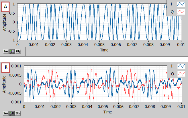
incompatibility of frequencies for the USRP carrier
Figure A is what I sent. Figure B is what I received. As I know that it is because there is a lag of carrier frequency. How can I use LabVIEW programming to retrieve my signal, in order to eliminate this effect?
Few things to check that could help you determine or refine the problem:
1. What are the profits? Are sufficient for the domain wireless?
2. can you reduce the amplitude of the baseband of the signal to a value less than 1? Sometimes a value high amplitude of 1 may cause problems.
3. how the waveform at the end of Rx looks like if you do not use the frequency Offset Correction VI in the VI Rx?
4. can you wire the two devices as well as SMA cables and then check the waveform? Any improvement?
5. read back the value of carrier frequency when put aside the Tx and the Rx and make sure it's equal.
6. make a simple smoke test to see that two devices can communicate with each other. Simple sound signal on a carrier and receive it on the side of Rx. You can use the examples of niusrp to do this smoke test.
Thank you.
-
Question about changing the refresh frequency for the perf of run-time statistics
Hello
I would like to know if there is no API or refresh rate of orders to change the provider.
For example when I train to recover PerfProviderSummary.getRefreshRate () disk performance statistics, I see that the refresh rate is set at 20 seconds (by default). Call of PerfProviderSummary.setRefreshRate (5) has no effect on future calls and the refresh rate remains at 20 seconds.
ESXTOP however to change the refresh rate up to 2 seconds.
Thank you and best regards,
Prashanth
Hi Julie,.
It is not possible to change the frequency of refresh in real time of 20 seconds. The vim. PerformanceManager interface is limited to a minimum of 20 seconds sampling period.
In addition, it is always recommended to call the QueryPerfProviderSummary API on the entity to verify the refresh rate and use this query for performance statistics refresh rate.
I hope this answers your concern!
-Angela-
-
Menu Module v2 supported for the selected state?
I can't understand if v2 menu module supports the selected state. I remember reading somewhere that it was planned to produce in the future, but it seems that the file /ModuleTemplates/Menu/Default/container.html has accommodations for her.
A resource if so, it would be appreciated.
By default I did, the JavaScript code is there in the updates page and not different from the normal version in this respect.
-
Web module is required for the export to the web server?
Web site module can do anything more that export dialog box, for just send pictures on a web server. If we do not want a gallery, export provides all the same options to exit a 72 dpi, sRGB jpeg dialog box?
Thank you, Tim
If you're just uploading images to a Web server you should not use the web module at all. Just use the export module. It offers many more options whereas scaling, sharpening, color space, etc...
-
Satellite A200-1AG - what modules of memory for the upgrade?
Hello!
I have a + * Satellite A200-1AG * +. I'm planing to upgrade the memory to 4 GB. Mine uses + (2x1GB) DDR2 - 667 Mhz + and I saw only 2 modules of 2 GB DDR2 - 667 Mhz + cost the same as + 2x2gb DDR2-800 +. I benefit in any way from this upgrade? Can I damage my laptop? I heard that my laptop will work anyway to 667 MHz, but I'd like to know your opinion about it before I buy it.
Thanks in advance!
Hello
You can buy both types of module. The point is that the fastest modules (DDR2-800) downgrade always compatible system at low speed. This would mean that the modules will run at 667 MHz.
So you n t destroy your laptop, it s just a feature. Everything will work correctly.
As far as I know your laptop runs at 667 MHz can accelerate.
-
change the frequency for the web service
I'm under LabVIEW Web Service with an application following the method shown in the example of weather monitor. But my problem here is that I have to keep clicking the Refresh button, then the Web Service can only update the latest data for me. Can someone help me to set an example on how to let the page Web of the Web Service automatically update the value without pressing the Refresh button. Thank you
First of all your customer needs to support it. If you use the HTTP Client in LabVIEW (GET.vi and so on) you cannot use this method. A normal browser should.
Take a look at the address book example FindContacts.vi.
The help topic linked in the previous post, you should get on the way as well. The news are scattered throughout the help file, but it should be possible to understand.
Basically, there are two output options for a web service VI: Terminal mode as used in the example weather and fashion such Stream used in the example address book VI.
Use stream mode and build the HTML page yourself, then sends it to the browser with Response.vi write. Somewhere in the top of the HTML page, you need to insert
If you need to return a string like
my title


If your browser supports Refresh,
this page refreshes in 5 seconds.

And add some real contents here
See also W3C .
Good luck
-
Sampling frequency for the output of an acquisition of data USB-6211 card?
Hello-
I use a CGI CMOS FireWire camera to read an interference figure, then using a transformed of Fourier transform spectral interferometery (FTSI) phase recovery simple algorithm to detect the relative phase between the successive shots. My camera has a linear 28 kHz scan rate, and I programmed my phase retrieval algorithm take ms ~0.7 (of a trigger of camera at the exit of the phase). I use the live signal to control a piezoelectric stack, by sending a voltage single sample to the analog output of a data USB-6211 acquisition card.
Send this output voltage increases the time of my loop 4 m, I would really like to achieve a 1 kHz or better sampling rate. Is the problem with my DAQ card or with the processor in my computer? The DAQ cards of NOR can support these speeds?
Thank you
-Mike Chini
Hey Mike,
With USB, your loop rate will be around or under 1 kHz, even on the best of the systems. USB has a higher latency and less determism PCI and PCIe. You can get rates AO one much better sample on a PCI card, potentially a PCI-6221. We have a few HAVE points of reference for targets of RT for PCI, / AO in a loop, you should be able to get similar performance in Windows, but if you do a lot other treatments may suffer from your local loop rates.
Hope this helps,
Andrew S
-
Hello
We need power RF amplifier with a function generator to create plasma in an ion source. The signal pulse duration must be 1ms long, repeated twice per second.
Today, we work in the following way: we spend the RF with f0 (aprox 1,995 MHz) frequency. After 20, we send a trigger signal passing frequency f1 (aprox 2.005 MHz). We keep this frequency for the rest of the pulse. However, the plasma that we generate is not 'constant' or stable during the whole impulse. If we smoothly change the frequency during the pulse we could improve.
We would like to do: use the frequency sweep: rather than use this frequency hopping, we would like to move smoothly f0 f1 (frequency scanning). Then F1 to f2.
As we have a PXI for data analysis, we believe using the arbitrary function generator of NOR: 5406 of NEITHER allowing the frequency sweep. However, in the book loads, it is not very clear, and I have a few questions:
-We can create a "list of frequencies. In the site OR below, it shows that the "minimum of Step' is 1.28us, which would be ok for us (I understand that the"minimum duration of Step"is the minimum time between 2 frequencies). However, the manual of the device "NI PXI/PCI-5402/5406 specifications" said the frequency list has a time step of 1 ms to 21s. What is the good?
-It is also said that the "duration of minimum list" is 1 s. For us, need us a shorter list that 0.5 seconds (we need to repeat the same pulse twice per second.). Is it possible to do what we want?
-At the end of the day, we would like to implement a control loop which modifies the list of frequencies in real-time.
http://zone.NI.com/reference/en-XX/help/370524L-01/nisignal_generators_help/features_by_device_smc/
Thanks for your help.
Best regards
Jose.Hi Jose,
You're right about the inconsistencies of the documentation. The minimum step was of 1 ms, but was changed to 1.28 µs to driver version 2.6. The help document has been modified to reflect that, but the specifications were not. I'll make sure that attaches.
The length of the minimum list is not listed in the book loads, and the latest version of the help the signal generators OR (driver version 2.9) lists the minimum list than the 1 step length. Aid has changed to the driver version 2.6.1 to clarify that the 1s meant 1 step. I've attached a screenshot of the help of the most recent.
There is an example that is installed with the NOR-FGEN driver called "Fgen Sweep Generator.vi". I would recommend from this for your application.
I hope that some of the inconsistencies in our documentation brightened. Please let us know if you have any other questions.
Elizabeth K.
Generators of signal produced technical support engineer
-
Configuration of the basic Source of time to master for the 9234
I have several cDAQ modules I use to collect data. I use vi to Write can Express to save data to a file of PDM.
When you examine the recorded data files, the measured data from NI 9215 provide pleasant timestamps to match how the DAQmx task has been set up--delaying the sampling frequency of 1000 with a 1 ms in the While loop. However, although in the same vi - different tasks, but the same while loop - horodateurs of the NI 9234 do not correspond to the task of DAQmx implemented - sampling frequency of 1000 with a 1ms delay. After reading the material provided with the NI 9234, I found that maybe the machine clean master Timebase Source. There were documents that says he can be configured to be originally of Timebase of Master for the other modules:
Configuration of the basic Source of time of the master for the NI 9234 (Interface FPGA)
It is desirable to have the timestamps for data measured across all modules to match. We do not have the FPGA Module for LabVIEW. Is there a method in LabVIEW for all modules use the same master time base Source? I assumed that because all the data collection has place in the same while loop by using the time delay of 1 ms it was forced through the code. This hypothesis seems incorrect from my review of the PDM data files.
The NI 9204 provides a trigger only.
Software:
Windows 7
LabVIEW 2010 SP1
Material:
CDAQ-9174 chassis
Slot 1: NEITHER 9204
Slot 2: NEITHER 9215
Slot 3: NEITHER 9234
Slot 4; Vacuum
Hi MgDAQ,
An important concept to note is that the 9234 uses a delta-sigma converter and a clock of oversampling to read analog data. There is an inherent delay of entry due to analog and digital filtering built-in. Since the 9215 has a lower resolution there will be a lag the 9234 and 9215 finished. I've included some resources below:
What are the for the NI 9233, NI 9234, and NI 9237 valid sampling rates? : http://digital.ni.com/public.nsf/allkb/593CC07F76B1405A862570DE005F6836?OpenDocument
Synchronization of DSA, S and X series devices with a NEITHER-DAQmx single task series: http://digital.ni.com/public.nsf/websearch/78E44565FD87E7D686257108007F94F8?OpenDocument
Synchronization with NOR-DAQmx of acquiring dynamic signals (DSA) products:http://digital.ni.com/public.nsf/allkb/A133ED27DF9BCC5986256F2E004BA342?OpenDocument
Have you tried to put two modules in the same spot? Alternatively, you can export the sample clock 9234 and tasks installation separately.
Best,
CARISA
-
Returned by DAQmxGetDevCIMaxTimebase for a NI 9361 module incorrect frequency limit
Hello
I have a NI 9361 module in a 9178 cDAQ chassis. My workflow is as follows:
(1) create a new task
(2) add a the meter inlet channel to the task
(3) the maximum basic rate of time meter using DAQmxGetDevCIMaxTimebase entry question.
(4) set the sampling frequency clock using DAQmxSetSampClkRate at the speed required in step 3.
(5) Perform other steps such as add a channel of analog input or external clock to the task.
I get an error in step 4:
Requested value is not supported for this property value. The value of the property may be invalid because it is in conflict with another property.
Property: DAQmx_SampClk_Rate
Required value: 100.0e6
Maximum value: 40.0e6
Minimum value: 22.250739e - 309
Why step 3 returns 100.0e6 when I put only a maximum of 40.0e6? Must I call another method instead of DAQmxGetDevCIMaxTimebase? I have attached my code for your reference.
Thank you
Varun heraud
The MathWorksThere is a difference in how the counters work for the 9361 NOR in the cDAQ and counters in other devices (including the cDAQ chassis counters). The 9361 OR use a chassis timing engine, so it does not require an external sample clock, and it transfers data to the bottom of basket on each sample clock. Therefore, there is a limitation on how fast that can occur and the DAQmxGetSampClkMaxRate function allows users to query this value. The counters on the USB-6211 USB 6351 require an external sample clock, and since they are one of the subsystems of the device, the maximum sampling rate is not dependent on engine, no data transfer time constraints so DAQmx does not support the property of max (for the tasks of meter) sample rate. For these devices, you get an error if the counters have no new data between the sample clocks (because the sample clock is faster than on the counter source input signal).
-
Calculation of derivative of clock for the NI 9234 module
Hello! I am relatively new to the use of material OR (and DAQ hardware in general), so this is probably going to be a really basic question.
We plan to use two 9181 chassis cDAQ with two modules NI 9234 sample data on 8 physical channels simultaneously at a rate of 25600Hz. As we use the 9181 chassis we cannot material synchronization as described in this topic:
«CDAQ-9181 will be out of the question because, as you said, it does not accessible PFI lines from the outside and you can not use a digital module for synchronization in a carrier case, because who was going to occupy the only available unit.»
We need the synchronization between the channels to be accurate to ±100ms. According to the http://www.ni.com/pdf/manuals/374238c.pdfspecifications, the time base internal master (fM) has a frequency of 13,1072 MHz and an accuracy of ± 50 ppm. I'm trying to calculate the maximum amount of the derivative of the clock, more than 1 hour. The selected sampling rate influence the result?
I think what meant Henrik was to connect the same signal to a channel on each of the two modules. This way, you have two digital versions of the same signal with each being scanned by a different clock. As long as it has the signal which can be identified in the worst case timing difference, you can determine that the sample [e] in a set of data has occurred at the same time (period a sample) as sample [k] with the other set of data. Then, you apply this synchronization relationship to all other channels in the two modules.
Strictly speaking, it is the difference in frequency between the two clocks, no drift. Data sheet specifies the precision of freqeuncy as +/-50 ppm, but specifies no drift at all. Drift has usually two components - temperature and duration. Drift in temperature is specified as ppm/degree, while the drift of time (also known as aging) can be specified as ppm per year. The two drift coefficients are usually smaller than the specification of the accuacy. It is not unlikely that the precision specification can include effects of drift.
If clocks drift significantly for the duration of your run, you may need to correct calendar several places in the data set. If the two chassis are physically close, any change in temperature will probably be very similar for both devices and aging is generally not relevant for periods of one hour. I suspect that the initial frequency differences are the only things that will be of interest to you. If a few ppm drift issues, let the two devices to heat for an hour before starting the test. This should be enough to stabilize temperatures.
Lynn
-
How to add a dependency to the library for the java service modules?
Hello
I try to add Google gson jar as a dependency of the sample of chassis (/ chassisRackVSphere-service) and I'm facing some problems with the installation of osgi.
////////////////////////////////////////////////////////////////////////////////////////
Report of resolver:
A Package Import could not be resolved. Resolver error data < Import-Package: com.google.gson; version = "0.0.0" >. Caused by the constraint missing bundled < com.vmware.samples.chassisrackvsphereservice_1.0.0 >
constraint: Import-Package: com.google.gson; version = "0.0.0" >
at org.eclipse.virgo.kernel.install.pipeline.stage.resolve.internal.QuasiResolveStage.process(QuasiResolveStage.java:46)
at org.eclipse.virgo.kernel.install.pipeline.internal.StandardPipeline.doProcessGraph(StandardPipeline.java:62)
at org.eclipse.virgo.kernel.install.pipeline.internal.CompensatingPipeline.doProcessGraph(CompensatingPipeline.java:73)
at org.eclipse.virgo.kernel.install.pipeline.stage.AbstractPipelineStage.process(AbstractPipelineStage.java:41)
at org.eclipse.virgo.kernel.install.pipeline.internal.StandardPipeline.doProcessGraph(StandardPipeline.java:62)
at org.eclipse.virgo.kernel.install.pipeline.stage.AbstractPipelineStage.process(AbstractPipelineStage.java:41)
at org.eclipse.virgo.kernel.deployer.core.internal.PipelinedApplicationDeployer.driveInstallPipeline(PipelinedApplicationDeployer.java:359)
////////////////////////////////////////////////////////////////////////////////////////
Here are the things I did based on the addition of the gson - 2.2.4.jar to the list of libraries (which I'll use my service module).
1 added gson - 2.2.4.jar to chassisRackVSphere-service\lib
2. added gson - 2.2.4.jar to the list of libraries referenced in STS.
3. fixed the ANT build file to add this jar to the classpath
< target name = "java-compilation" depends = "clean" description = "do not select objective in-house." >
< javac includeantruntime = 'false' destdir = fork "${CLASSES}" = "true" debug = "on" >
< path src = "${basedir} / src/main/java" / >
<!-< path src = "${basedir} / src/test/java" / > for future test-> files
< classpath >
<! - remove this if you are not using the SDK with java - >
< pathelement path="${VSPHERE_SDK_HOME}/libs/vsphere-client-lib.jar"/ >
< pathelement path="lib/commons-logging-1.1.1.jar"/ >
< pathelement path="lib/gson-2.2.4.jar"/ >
< / classpath >
< / javac >
< / target >
4. fixed the manifest file to include the package gson
/////////////////////////////////////////////////////////////////////////////////////////
Import-Package: org.apache.commons.logging,.
com.google.Gson,
com VMware.vise.Data,
com VMware.vise.Data.Query,
com VMware.vise.Data.Uri,
com VMware.vise.vim.Data
/////////////////////////////////////////////////////////////////////////////////////////
I don't know what I'm missing. How can I add third-party libraries for the service module (in this case chassisRackVSphere-service)? Any help is appreciated.
Thank you
Shankar
You forgot a step described in the FAQ ""How to use 3rd party java libraries?', that is to make your available on the server gson library. " An excerpt from the FAQ:
Formatted as OSGI bundles libraries should be in a known location on the server:
- In development mode you can copy in Server/repository/usr, one of the default directories for the loading of libraries (you must restart the server).
- If the server is already running you can copy also in Server/Pick-up because the beams will be deployed hot (i.e. without having to restart, but this requires you to deploy your plugin after the library, see Note 2 below).
- Finally, you can keep in their current location and add a path in server/configuration/com.springsource.repository.properties.
- In production mode , that your plugin is installed as a plugin package, it is neither practical nor recommended to add libraries to server/Pick-up or Server/repository/usr on your production server. Instead you must include them in the directory plugins of your package and your .war and .jar packages. You will also need to list Bundle-SymbolicName of plugin libraries - package.xml.
-
Portege R500 - 11K with the XP drivers for the UMTS/HSDPA/EDGE/GPRS module
Hello world
I have some pre-sales questions on laptop nice R500 - 11 K.
I want to install XP pro on this machine. The device is delivered withou XP Recovery CD. (model 11A C)
There are beautiful collection for R500 XP drivers so I can install XP manually.NES http://eu.Computers.Toshiba-Europe.com/cgi-bin/ToshibaCSG/download_drivers_bios.jsp?service=eu&mode=allMachi & action = search & teddProduct = 747
Model K 11 has another installed UMTS/HSDPA/EDGE/GPRS module unlike models. Great!
What about drivers for this module?
There is not any UMTS/HSDPA/EDGE/GPRS modem drivers listed in the list of drivers for Vista or XP or device.So the question is, if I want to install XP, where can I find the driver for 3G module manually?
Is the component of another driver driver?
-Does anyone know the name and the type of this module 3G? In my view, the module is provided by aint Toshiba of the seller.Anyone have any experience with XP on R500 11 K?
Thank you
Marek
Hmm, you're right.
The pilot of the 3G is not available on the Toshiba pageSeems that the driver has been downloaded not however the Portégé R500 was delivered with a * Novatel MSM6275 card * ThreeG (Qualcomm should be manufacturing the chip) and if you want, you could try to download the driver of the 3rd site part.
Good luck
-
Satellite L20-100 - what modules of RAM can I use for the upgrade?
Hi all
I have TOSHIBA Satellite L20-100 and I need to upgrade the ram memory up to 2 GB.
I found these models on the internet but I don't know that it is compatible with my computer laptop or not.the following module on the eBay store:
* 1 GB Kingston DDR2 667 Mhz 1 GB DDR laptop 2 NB RAM *.
* Hynix 1 GB RAM DDR2 5300 s - computer notebook memory 667 MHz *.
* ASint 1 GB DDR2-667 PC2-5300 PORTABLE 200 pin MEMORY *.Already now I have 512 DDR2 667 Mhz
Or any knows from where can I update the correct RAM?
Hello
Theoretically, you can use all modules store because all the modules to meet specifications, DDR2-RAM, 1 GB, etc. for example.
In your case, I'd take the Kingston RAM. I've never heard ASint RAM, but I have good experiences with RAM Kingston. I always use Kingston RAM to upgrade my notebooks and never had any problems.
Last but not least, you can also buy RAM of an authorized service provider.
Good bye
Maybe you are looking for
-
Mozilla Crash Reporter occurs whenever I try to start Firefox.
I've been running FireFox for years. I use Windows 10. Today, when I clicked on FireFox mentioned, I got a "Mozilla Crash Report" dialog box with the following information: boxAvailablePageFile: 15220731904AvailablePhysicalMemory: 13313277952Availabl
-
Portege R700-172 how to replace SSD
How can I replace the SSD by a standard HDD? Toshiba has used connectors in the R700-172. Post edited by: tron
-
I'm unable to send or receive messages non-iPhone on my iPhone 6.
I can't send or receive text messages to users who are not iPhone users. I checked all the settings by following the instructions by apple and all useful users on the internet. I have also reset the settings and reset the network settings, but did
-
How to install the biomedical toolkit to myRIO 1900 RT target
Hello I try to install biomedical toolkit to myRIO using NI MAX. However, after that I installed on my system and ran the software Assistant in real-time to myRIO, I couldn't find the box tool as shown in the pictures I tried quitting biomedical scre
-
Download iTunes files in Windows Movie Maker on a downloaded CD?
Hey,. I'm doing a movie in WMM, and I tried to go into iTunes and import the music on a CD that I had already imported into iTunes. He gave me something the codec is not installed. For the record: I have already read the answer of Yes, and it does no