Module of interfacing SMU 8115
IAM using the SMU 8115 module to connect an Instrument.I want to use the ethernet communication. So please suggest me which is the Commom TCP/IP or UDP protocol? Can I use Protocol series?
Hi Sam,
You need to generate code in time real PXI.
Procedure for establishment of the RT code
1. create the new empty project
2. right click on the project tree and select new--> targets and devices
3. Select your PXI system and set up your project with all the options available.
4 TCP transceiver code developing PXI and build the EXE and deploy
5. receiver/transmitter TCP code developed on PC and send/receive data on PC.
You can build simple read and write the code and check the data exchange between the host PC and PXI
Tags: NI Software
Similar Questions
-
SMU-8115 there wireless internet capabilities
With the help of an SMU-8115 controller in my 1062 q. I was wondering if it has wireless capabilities? have not yet received while trying to plan if I needed to implement things differently in our facilities to icorporate a wired connection.
Hello
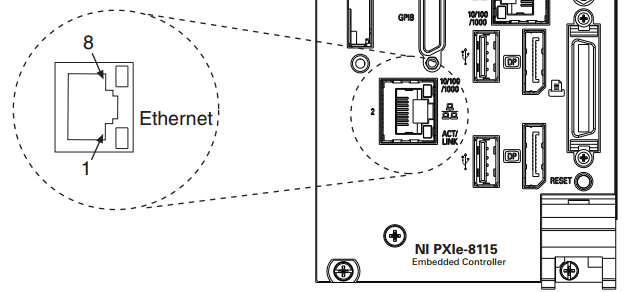
In general, the controllers do not have Wi - Fi capabilities. Specifically, the SMU-8115 only has one Ethernet port on the front and no built in Wi - Fi capabilities. In general, this controller is directly connected via the Ethernet connection to the front (see picture below). However, you can use a USB-Wi-Fi antenna (for more information,click here for a google search on "Usb Wi-Fi adapter" ).
I hope this helps.
Eric-E
-
HOL-SDC-1303 Module 2 - Interfaces disappears on distributed router (edge-2)
When you try to complete the configuration for 'area to the mappings of Interface' for the logical distributed router 'edge-2', I continue to experience the following issue:
There is no interface available in the drop down "Interface." As soon as the cancellation of the configuration of the "area of Interface Mapping", I return to the 'Manage-> settings'tab to "edge 2". The system simply "revivals" and never shows the submenus "Interfaces" or "Configuration". In fact, all 3 interfaces that were configured previously, (Uplink_To_Perimeter, App_Interfaceand DB_Interface), disappeared. That's why I have no interfaces available to select when you complete "area to the Interface mappings.
I tried to use different browsers, deletion and recreation 'edge 2"(router distributed logic) from scratch, etc. and always until the end with the interfaces"disappear"when I try to complete the 'area to the mappings of Interface' for OSPF.
Everyone knows this failure mode? Any suggestions on how to move forward?
Kind regards
Brian
It is a known problem in the lab environment that we have worked with engineering on where in general correct updating of the browser itself. We work to understand exactly what causes this problem within the laboratory environment and see if we can correct. Another measure corrective would be close IE and reopen that will also correct generally information center display properly, most often seen when adding interfaces to the VDR during laboratory exercises.
-
SMU - connection to the modules in the chassis
Hi all
Sorry for the rather simple question.
I'm trying to implement a new PXI system.
The implementation is the following: A PXIe1078 chassis with controller embedded SMU-8115, 4065, 2526, 4844 and 6220 cards PXI chassis. With the help of MAX, I am able to identify all the different pieces of equipment and everything seems to work ok.
I worked on the cRIO for several years and up using a similar approach strives to implement the project and to connect to and adjust the lighting of the user.
However, I don't seem to be able to work on the way to pick up the cards on the chassis?
Specifically for the 4844 PXI card, I used the utility OR OSI and been able to put in place the sensors and take readings so I'm happy, there is communication. I just don't seem to be able to find how to use it through LabView.
Can someone point me in the direction of the online samples? I searched but nothing helped and osi didn't example to load on my system, when I installed the software (v2.0) osi.
Thank you
DOM
Hi Dom,
To ensure that your cards display correctly you must install the driver appropriate for each card.
For the DMM:
http://www.NI.com/download/NI-DMM-3.1/4125/en/
For the switch, you will need the driver switch OR or NI DAQmx:
http://www.NI.com/download/NI-DAQmx-9.9/4707/en/
http://www.NI.com/download/NI-Switch-4.8.0/4333/en/
You will also need the NI DAQmx driver for the 6220 OR.
Once you have installed the drivers, the cards must all appear in NI Measurement and Automation Explorer (MAX NOR). You can then program the cards using their respective drivers in the measures of e/s palette.
Best regards
Chris
-
Can you have SMU 1062 q turn on without using the power button
I use a q SMU-1062 for a test project that will take place inside a protective case. The power button on the chassis will be covered by a plate on the protective case that make it boring and difficult to switch on using the power button on the chassis. The chassis will be plugged into a power strip of travel - lite which is mounted in the case. Is it possible that I can have the power to frame on when I turn on the power strip?
I found another route. In the controller BIOS, I changed the parameters of loss of AC power to TURN on after that AC is returned. This allows me to use the power strip in my configuration to control the electric network distributed to the controller. The following steps will describe how I got this.
- Power of the SMU-8115 controller.
- A message will appear on your screen, press
to enter SETUP - Select 'Remove' (quickly, because you don't have a lot of time before the window disappears and the controller continues to load normally.)
- This will open the main Menu of the BIOS
- Select the Advanced tab (use the arrow keys to highlight the selections and the different tabs, select a setting change with 'enter'
- Select > Configuration power and rest
- Change the configuration to power on when power is restored.
The controller can be normally close by using the start menu, and "shut down".
Start button / stop of the chassis is still capable of turning the power on to the controller, but now when I shut off the AC power strip and then return power, get the controller chassis.
-
The system modules and threads?
(1) are grouped within the cod even modules of the system?
(2) will run the modules of the system since a separate queue UI event thread? Basically, do I need another thread to do the work of the fork?
(3) I noticed that the phone application is divided into 2 modules: api (1) (2) app.
Is this a good practice? API modules for interfaces maybe. How do we export Service for consumption by another application?
Thank you
G
In most cases, an operation that takes more than a few milliseconds to complete should be done in a separate thread, especially in a user interface application. Of course, this is not mandatory. The objective is to ensure that the user appreciates their overall experience with their device - not just with your application.
Edit: Oh, and I almost forgot to answer your original question. To my knowledge, System applications share the CPU as an app we write are supposed to. In this sense, our applications are on the same level as the rims. Of course, I'm sure rim are multithreaded to some extent, but they are not running in a separate environment from our.
-
Interfaces of WISN gone after switch-upgrade
Hello
I have a 6509 with a sup720 (regular, not a 10GE) and a blade WISN in the Groove 3.
It worked fine until I did an update of the IOS on the 6509. I went from s72033-ipservicesk9_wan - mz.122 - 18.SXF13 s72033-advipservicesk9_wan - mz.122 - 33.SXI3.
Now, I can't reach my WISN-blade more. When I look in the configuration running on the switch there is no gigabit on module 3 interfaces, in the config it even does not mention a 3 module.
However when I do a "module to show" the WISN is reported with a status of "ok". When I do a "show WISN module 3 controller 1 status," he also told me that his 'Oper-up' and all addresses are in place, even the service IP-adres (that I do not understand because he can get this address by DHCP from the switch).
The WISN is running 6.0.188.0.
Have you ever seen such behaviour?
THX
From version auto-LAG sup720 SXI was the only option to configure the port of WISN-channels (global config WISN orders). The gigabit actually and port-channel interfaces will the WISN are no longer visible in the configs.
-
Stop of trip completed with warning of interface
Hi all
For a sales order, the line has been shipped where the line are as taken showning and according to delivery status is closed with the next step is showing that "run the Interface." While I presented Interface travel stop, completed by the caveat. The log file says:
---------------------------------------------------------------------------
Execution of the expedition: Version: 12.0.0
Copyright (c) 1979, 1999, Oracle Corporation. All rights reserved.
Module WSHINTERFACES: Interface travel Stop - SRS
---------------------------------------------------------------------------
Current system time is April 20, 2009 07:31:03
---------------------------------------------------------------------------
* Starts * April 20, 2009 07:31:03
* Ends * April 20, 2009 07:31:03
Stop of trip interface is complemented by the caveat
---------------------------------------------------------------------------
Beginning of the FND_FILE log messages
---------------------------------------------------------------------------
From WSH debugger == > 20/04/2009 07:31:03, Session ID = 2850630
The current shipping related debug settings are the following:
OM: Debug level == > 0
INV: Debug level == >
WSH: Active Debug == > Yes
WSH: Debug prefix file == >
WSH: Debug level == > statement
WSH: Debug logs directory == > /dtmp
WSH: Debug Module == > %
Enter WSH_SHIP_CONFIRM_ACTIONS. INTERFACE_ALL_WRP (WSHDDSHB.pls 120.19.12010000.3) (20/04/2009 07:31:03)
P_MODE == > ALL
P_STOP_ID == > a NULL value
P_DELIVERY_ID is > 2888
P_LOG_LEVEL == > 1
p_organization_id is > 381
p_num_requests == > 1
p_stops_per_batch == > 1
l_req_data == >
Enter WSH_SHIP_CONFIRM_ACTIONS. INTERFACE_ALL (WSHDDSHB.pls 120.19.12010000.3) (20/04/2009 07:31:03)
P_MODE == > ALL
P_STOP_ID == > a NULL value
P_DELIVERY_ID is > 2888
P_LOG_LEVEL == > 1
p_organization_id is > 381
p_stops_per_batch == > 1
INTERFACETRIPSTOP: LOOKING FOR STOP FOR DELIVERY_ID 2888
l_stop_id is > 3031
InterfaceTripStop: treatment, stop_id 3031 for INV OM DSNO
l_inv_interface == > 1
l_om_interface == > 1
l_dsno_interface == > 1
l_interface_mode == > DSNO OM INV
l_stop_id is > 3031
l_override_wf == > N
Ship to deliver workflow is enabled for one or several deliveries related to that case == >
Ship to deliver workflow is enabled for one or more deliveries on this S
Back to top
Interface_All: jump stop_id 3031
========================================================================
l_stops_count == > 0
InterfaceTripStop: no stop is processed without being referred to as interface lines
five.
errbuf == > travel stop Interface is complemented by the caveat
RETCODE == > 1
l_completion_status == > WARNING
Out of WSH_SHIP_CONFIRM_ACTIONS. INTERFACE_ALL (20/04/2009 07:31:03,.01 seconds)
Automatic remediation of == >
l_recs = 0 == >
errbuf == > travel stop Interface is complemented by the caveat
RETCODE == > 1
l_completion_status == > NORMAL
Out of WSH_SHIP_CONFIRM_ACTIONS. INTERFACE_ALL_WRP (20/04/2009 07:31:03,.03 seconds)
Summary of the expedition of the API calls *.
WSH_SHIP_CONFIRM_ACTIONS. INTERFACE_ALL_WRP: 1 calls:.03 seconds
WSH_SHIP_CONFIRM_ACTIONS. INTERFACE_ALL: 1 calls:.01 seconds
*****************************************************
Thanks in advance for your help.
Kind regards
Jyoti
Published by: Jyoti.Mohanty on April 20, 2009 02:46Hello
This problem is documented in 785934.1 (Metalink doc).
Summary of the solution is given below. Please, make sure you read the document above to confirm that the solution applies to your environment.--
1. go in the liability: System Administrator.2. go to profile > system.
3. the profile of queries option "WSH: ship instead deliver workflows ' and set this value to 'Yes'"
at the level of the Site.4. test the issue again.
5 migrate the solution as the case in other environments
-
Is it possible to add a simulated device NI DAQmx device or modular Instrument?
Hello
I want to simulate SMU 8115 module without hardware. Is this possible? If so can I add the device in simulated NI DAQmx device or modular Instrument?
HM, these are several very basic questions...
The controller (8115) is a "full" computer other than housing, power and cooling. At least three components are the chassis, in your case the SMU-1062 q.
The controller can be managed by a Windows base OS (e.g. Windows 7) or in time real ("RT"). So what you have installed on the 8115?
In both cases, communication with this additional controller by an external, laptop or PC is best done by Ethernet. You can use different protocols over Ethernet as a TCP/IP protocol based on measurement or using shared Variables OR.
NEITHER DAQmx is a hardware device driver. The purpose of this is to use a National Instrument based measurement device in a computer. If you want to use a hardware OR your SMU system, it is very likely that you need to have installed on the controller of 8115 DAQmx. DAQmx is available for Windows, as well as regards to the RT
DAQmx in this case of use don't gives you direct access to the devices in the SMU over Ethernet chassis by * all * external computer. You write an application that will run on the DC 8115 interface (or 'relay) data to your external computer.
hope this clears things up,
Norbert
PS: You should ask your branch to send someone to you... I think a direct discussion with an employee OR should be beneficial to you. Normally, a sales representative is sufficient as a VRP NOR is quite technical.
-
Project Explorer can not detect my PXI-7952R
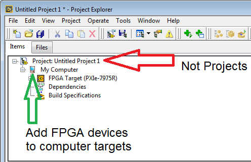
I use PXI-7952R and SMU-8115 in a chssis SMU-1071. When I opened MAX, my PXI7952R camera seems to be detected (if I'm not mistaken). However, when I try to open a new FPGA project, the Project Explorer can't detect it. is this a configuration problem or the device?
PS: I am really new in this field.
If you want to add a remote target of a project, you right-click on the project and select new > objectives and devices like you were doing it. However if you want to add a FPGA device, you select the target who has access to the FPGA, just right click and select new > targets and devices. In this case, you should be good by clicking in the project is 'my computer '.
Also make sure you have installed NI FlexRIO.
-
NOR-RIO Patch Nov 2013 on the PXI controller
Hello
We use SMU controllers like the LV RT 2012 SP1 8115. We have also a card FlexRIO in the chassis, and we use FIFO write often.
From what I've read on the November 2013 Patch NOR-RIO (http://digital.ni.com/public.nsf/allkb/95CF25A09DB91FEE86257BE8006193B7?OpenDocument), we should update the systems of RT, but I do not see this option in MAX.
After you have installed the patch, I have the documents mentioned 12.1.1 with a file mite.cdf inside. But Max, I don't see any updates to the target. I still have a single NOR-RIO mentioned 12.1 which is already installed on the RT system.
So, how to install this hotfix on the SMU-8115 OR with LV RT 2012 SP1 and 12.1 OR RIO?
Also strange: when using the OR update service again and expand the updates and Service Packs the Patch OR-RIO reappears in the list of critical updates.
Thank you
Daniel
The component listed in the patch updated is unfortunately a component hidden which is automatically installed when you install your system remotely RIO. Relocation of the NOR-RIO of MAX component to your remote system should be sufficient to force the patch to apply.
Note recommended sets of software are not supported under PXI, where is expected.
-
Camera not selectable in "Session".
Hello
I have the following configuration:
A 'ELIIXA + 8 k/4 k' camera, connected to an SMU-1435 module in the SMU-1082.
My goal is by program aquire images in LabView (14.0.1 / 32-bit)
In MAX, I can take pictures very well.
I wrote a simple program to run on the PXI system, but I can't select the camera like "cam0" (or something) at the Session 'en' - selector.
(Yes, I deploy the VI for PXI)
This is a screenshot of MAX (German version)
Why the camera appears as a "Channel 0", as opposed to "cam0?
Can I change this?
How can I use a camera that presents itself as "Channel 0" in LabView?
This is my test VI, it displays the error code "-1074360311 IMAQdx Open Camera", as is expected, when the camera is not correctly selected.
There seems to be something fundamental, that I am completely missing.
Thank you for your help.
Hi SeWi,
Since you have a camera link you can yous the driver not the IMAQdx IMAQ.
What is the difference between NOR-IMAQ, NOR-IMAQdx and NOR-IMAQ i/o? -National Instruments
http://digital.NI.com/public.nsf/allkb/0564022DAFF513D2862579490057D42E?OpenDocument -
PpiEnableInterrupts returns error "Invalid Length specified"
I work with IVI VISA PXI plug in modules OR (defined by IVI-6, 3). Almost all of its functionality works perfectly - like module list, attributes and access the memory space, etc... The only problem I got is interruptions. 'PpiEnableInterrupts (__in PpiHandle handle, __in ViUInt16 queueLength)' returns 0xbfff0083 'specified length is invalid error code. " I tried with different values of queueLength... or actually, I did a sweep from 0 to 1024. in all cases, the same error status is returned.
The material I work with is the following:
* Chassis: NOR SMU-1071
* Module system: Ni-SMU-8360
* Module that I work with the help of the plugin: OR PXI - 6509 (DIO)Versions of the software:
* OR VISA: 5.4
* NI PXI Platform Services: 4.0
IVI VISA PXI of the NOR plugin (NiViPpiP.dll & NiViPpiD.dll): 5.4.0.49152I know that PXI-6509 generates interrupts...
Any ideas why PpiEnableInterrupts does not work? Maybe its because the module is PXI SMU not?
Dear bartek-o,
I searched our resources to see if we have a better explanation for this error. What I've found, is that it is especially caused by the configuration of the interrupt functionality error.
Please consult this document: http://www.ni.com/white-paper/3142/en/There is a section that says:
Tip: If you write an instrument driver, let generates interrupts disabled during the initial development phase, even if you plan to implement of the interruptions. It is often useful get the basic functionality of driver before trying to add support for the interruption of work. Interrupt management can be added to the. INF file by running the wizard VISA Driver Development again.I suggest that you open VISA Driver Development Wizard and reconfigure the interruptions component generates. It is possible that it is not properly set / and / or not allowed at all.
Please get back to me if you could try this!
Best regards
Peter
-
Connection USB CAN use a map to a PXI chassis
I have an SMU-1078 chassis with an SMU-8115 Pharlap controller running. The chassis contains two maps XNET for CAN communication. All the slots in the chassis are full so I can't add another card XNET. Instead, I tried to connect a USB-8473 CAN map to a USB port on the front of the chassis on the assumption that I could program my LabVIEW project. This seems not to be possible, and I asked my support of local technical who do not feel that it is possible.
I have to say that MAX can see the card (seen in RAW format), and I can bring a VISA reference for her in LabVIEW. However, I can't tak on the device using the API CAN frame. I also connected a USB-6008 card to the chassis and the same applies, you see, but can't talk about it.
I understand that the 6008 use DAQmx and it's a Windows driver but everyone was able to snag a USB card on the front of a PXI chassis and talk him to LabVIEW?
Thank you
Malcolm
Sam_Sharp wrote:
I highly doubt that it will be possible if you use LabVIEW RT on the chassis. Should NEITHER create Pharlap drivers for the card CAN
Yes it would, and I believe that NI CAN 2.7.3 has support for Pharlap.
http://www.NI.com/download/NI-can-2.7.5/4143/en/
There maybe other versions. Basically, you need to install on your host machine, then use MAX to send the program and drivers to the PXI chassis, so you can write LabVIEW code for RT target that uses these drivers.
-
problem with Agilent GPIB 8510C Network Analyzer
Hello
I downloaded the Plug and Play (project-style) driver for Agilent 8510C Network Analyzer. The basket has address suite:
Address of HP - IB 8510: 16
The system bus address: 21
HP - IB source address: 19
Criterion address HP - IB: 20
Plotter HP - IB address: 5
Printer HP - IB address: 1
The basket includes 8510A processor, source RF, series of tests and tracer. There is a GPIB port on the plotter that connects 3 8510A processor, RF source GPIB port, and the value of Test. I connect the GPIB PC port to the GPIB port. The grid gives me an error: "ADDRESS ERROR: SYSTEM BUS ATTENTION."
My driver for LabView Plug and Play (project-style) cannot detect any address on the bus.
I tried IO libraries Suite Agilent, but he could not detect them.
Is there a problem in the connection ports 3-module GPIB interface in the basket or am I missing something? I'd appreciate any help.
Thank you
Nabil Gharib
yasmain62 wrote:
Hello
I downloaded the Plug and Play (project-style) driver for Agilent 8510C Network Analyzer. The basket has address suite:
Address of HP - IB 8510: 16
The system bus address: 21
HP - IB source address: 19
Criterion address HP - IB: 20
Plotter HP - IB address: 5
Printer HP - IB address: 1
The basket includes 8510A processor, source RF, series of tests and tracer. There is a GPIB port on the plotter that connects 3 8510A processor, RF source GPIB port, and the value of Test. I connect the GPIB PC port to the GPIB port. The grid gives me an error: "ADDRESS ERROR: SYSTEM BUS ATTENTION."
My driver for LabView Plug and Play (project-style) cannot detect any address on the bus.
I tried IO libraries Suite Agilent, but he could not detect them.
Is there a problem in the connection ports 3-module GPIB interface in the basket or am I missing something? I'd appreciate any help.
Thank you
Nabil Gharib
You really should read the 8510 manuals C.
Page 4-10 of the 8510C on-site repair, it indicates
For systems equipped with controllers, connect all devices and
the controller on the GPIB connector the 85101.The 8510C of operation and programming manual includes steps for checking the system setup.


Maybe you are looking for
-
If I move the cursor over the letters or numbers that they snap up bright. In about 30 seconds, they return to the hazy State. This only happens on Firefox. not to explore or my regular computer programs.
-
Problem of Medical ID health with emergency contact app
IPhone 6: any attempt to add emergency medical Ref. contact. It goes to my contacts but they are grayed out and unselectable. What's wrong?
-
t440s... upgrade the wireless card and the difficulties
White and black power connector that connect to the card... how people normally made / twist these are in place?
-
create the string in the array item
Problem... I want to create a unique string item. My entry is an array of integers 1 d of two elements, for example (10, 5) and the output should be a part of string in the form of "10.5." Just a single item and not a table. Any tips or ideas? Thank
-
I have two machines of 2012 sql dev not in areas. I'm trying to configure replication between the two men. I created the database of distribution on sql1. The publication database is on sql1. The snapshot directory is a share on sql1. The subscriber