myRIO analog input express file missing VI (n samples)
Dear users,
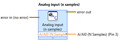
I'm reading of analog data with an express VI in myRIO. This works with analog input (1 sample), but fails with analog input (n samples) due to a file missing "myRIO v1.1 FPGA Throughput.lvbitx".
I Googled it and searched on ni.com, but nobody seems to have the same isssue (I guess because of the myRIO is quite new at this time)
Thank you!
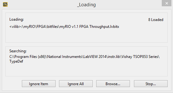
OK, now we have a solution. The problem is, that the high-speed FPGA personality is not part of the default installation. You must download the NOR broadband add-on for myRIO 2014 (which is of ~ 20 MB) and now it works. The download link is: www.ni.com/download/ni-myrio-software--2014/4938/en/ .
Tags: NI Software
Similar Questions
-
How to merge and write analog inputs, and export data to a tdms file?
I have a vi who writes analog inputs in tdms files. I also want to write the analog output signals, which are 2d table entries in the same PDM file with additional columns representing the analog output signals. How can I get this feature?
Ashaironix wrote:
Hey Crossrulz,
So you're saying that writing two files tdms with entries as HAVE and AO, will write everything in a file single tdms AOs and Ais?
N ° you write in the same file, just different GROUPS. TDMS is a hierarchical data format. You have the file, group, channel. Waveform data will actually in the channel data. But you can have metadata on any level. So, I do a group I and a group of the AO.
-
Outlook express folders missing files?
When I open outlook express I noticed that all the mail files are empty. I found the files in 'my documents' on my computer. dbx files which I can't open. How to restore Outlook express files? Thank you
Unless you have moved the storage folder, they should be in C:\Documents and Settings...
I don't care:
Two reasons the most common for what you describe is disruption of the compacting process, (never touch anything until it's finished), or bloated folders. More about that below.
Why OE insists on compacting folders when I close it? :
http://www.insideoe.com/FAQs/why.htm#compactWhy mail disappears:
http://www.insideoe.com/problems/bugs.htm#mailgoneAbout file Corruption:
http://www.Microsoft.com/Windows/IE/community/columns/filecorruption.mspxRecovery tools:
If you use XP/SP2 or SP3, and are fully patched, then you should have a backup of your dbx files in the Recycle Bin (or possibly the message store), copied as bak files.
To restore a folder bak on the message store folder, first find the location of the message store.
Tools | Options | Maintenance | Store folder will reveal the location of your Outlook Express files. Note the location and navigate on it in Explorer Windows or, copy and paste in start | Run.
In Windows XP, the .dbx files are by default marked as hidden. To view these files in the Solution Explorer, you must enable Show hidden files and folders under start | Control Panel | Folder options | View.
Close OE and in Windows Explorer, click on the dbx to the file missing or empty file, then drag it to the desktop. It can be deleted later once you have successfully restored the bak file. Minimize the message store.
Open OE and, if the folder is missing, create a folder with the * exact * same name as the bak file you want to restore but without the .bak. For example: If the file is Saved.bak, the new folder should be named saved. Open the new folder, and then close OE. If the folder is there, but just empty, continue to the next step.
First of all, check if there is a bak file already in the message. If there is, and you have removed the dbx file, go ahead and rename it in dbx.
If it is not already in the message, open the trash and do a right-click on the file bak for the folder in question and click on restore. Open the message store up and replace the .bak by .dbx file extension. Close the message store and open OE. Messages must be in the folder.
If messages are restored successfully, you can go ahead and delete the old dbx file that you moved to the desktop.
If you have not then bak copies of your dbx files in the Recycle Bin:DBXpress run in extract disc Mode is the best chance to recover messages:
http://www.oehelp.com/DBXpress/default.aspxAnd see:
http://www.oehelp.com/OETips.aspx#4A general warning to help avoid this in the future:
Do not archive mail in default OE folders. They finally are damaged. Create your own folders defined by the user for mail storage and move your mail to them. Empty the deleted items folder regularly. Keep user created folders under 300 MB, and also empty as is possible to default folders.
Disable analysis in your e-mail anti-virus program. It is a redundant layer of protection that devours the CPUs, slows down sending and receiving and causes a multitude of problems such as time-outs, account setting changes and has even been responsible for the loss of messages. Your up-to-date A / V program will continue to protect you sufficiently. For more information, see:
http://www.oehelp.com/OETips.aspx#3And backup often.
Outlook Express Quick Backup (OEQB Freeware)
http://www.oehelp.com/OEBackup/default.aspxBruce Hagen MS - MVP [Mail]
-
one of the icons at the top of my software is missing. I have those for: open the safe, files, print, share files, customize, reminder, BUT THE ONE for SOULIGNANT A WORD or EXPRESSION IS MISSING, then delete the page, etc. I have Acrobat Pro 10. How to get back the icon and the missing function? I would just reinstall, but I get the message that I don't have a legal copy of the program. However, I bought and paid for it. Thank you very much for your help! Carolyn
Add them to your quick tools. Go help > Quick of the tool.

I've added these tools to my quick tools, as follows:

Also see this article: Adobe Acrobat X Pro * databases the workspace
-
Problem with a precision of analog input on PCI-6111
Hello
I'm reading an analogue signal which varies from 0-11 V using a card of acquisition data PCI-6111. The signal comes from a Tube set (PMT) which is part of a microscope configuration, so it is very important that the resolution of the analog input signal be as wide as possible generate quality images. According to the data sheet for the PCI-6111, the analog input resolution is 12 bits, which should correspond to a sensitivity of ~2.686 mV for my voltage range.
To test this, I set up a task to analog input with a 0-11 V voltage range to read samples of an analog output, which I wrote a simple waveform. Since the 16-bit analog output resolution that I assumed that it would not limit the accuracy of this measurement. I have attached the VI I used for this measurement below. The analog input data are saved not truncated in a text file.
Analyzing these data, I found that the real input sensitivity is ~9.766 mV, corresponding to levels of voltage exactly 1126,4 and ~ 10 bits.
Is there a reason why the resolution of analog input is much lower that it is indicated on the card? What are some of the ways I could improve the sensitivity of this measure?
Best,
Keith
Sorry, when you mentioned the specs, I thought you already had them. If this did not come with your Board of Directors?
-
reading of the analog inputs with RPC
Hello
Because LabVIEW can not handle this (in VI; the value that you have saved the excel file has not been the same, that I saw during the measurement...) This confused me for a long time
 ), I want to write a C++ program (IDE: Dev - C++) which can read & record 2 analog inputs of the NI USB-6009 box. For this, I looked for an example of National Instruments and I found a little. But my problem is that I can't even use any example, because it has always held a mistake, after that I have compiled and started.
The error once the task has been created and has the :-200220 error number with the description "device identifier is invalid. But I do think that its invalid, because it's the xP example
I must say that I am new in programming C++, which means I could have a rookie mistake. And I couldn't find documentation or something for the NOR-DAQmx library.
Someone has similar problems with DAQmx and C++ and know how to fix? I don't really know what I can do now without a working example or documentations...
Hi Mario
It's the same thing. You didn't just save all of the data:
Please take a look at my comments in the attached VI.
Christian
-
I use an analog input on a PCI-6224 and are having problems with the clock source
I use an analog input on a PCI-6224 and are having problems with the clock source. I'm trying samples of 16 different analog inputs very quickly. I have the sample mode: Timed Single Point material. The rate, that I am running is the maximum (250 kHz (15625Hz per channel)). I left the default clock source and trying to taste several times. The analogue input works for a short time (2-3 seconds) and then everything stops. I'm doing something wrong or is there something I'm missing? Any advice would be great.
That's how you samples using the sample clock clock. If you see a delay then something is wrong with how you track/data visualization.
Single point NI the hardware is for PID control with a real-time operating system.
-
What is the minimum response of analog input, through DSP online, output analog time?
Hello experts!
I want to know if it is possible to get a very quick response latency (~ 1 ms) sound recording (analog input), through online registration (DSP online), the presentation of his (analog output) processing, by using the DAQmx programming codes. My system of NEITHER includes NOR SMU 8135, SMU 6358 DAQ Multifunction controller and SMU 5412 arbitrary signal generator. I also have access to the latest version of Labview (2015 Version) software.
My project is on auditory disturbances, which inovles record vocalizations, manipulating the recorded vocalziations and then present the manipulated vocalizations. My current idea of how to achieve this fact triggered output voltage after reading the input using DAQmx Read samples. DAQmx Read output is filtered online and then passed as input for the DAQmx writing for analog output. For purposes of illustration, examples of code are presented below. Note for simplisity, codes for the trigger part are not presented here. It's something to work in the future.
My question here is If the idea above should be reaching ~ 1ms delay? Or I have to rely on a totally different programming module, the FPGA? I am very new to Labview so as to NEITHER. After reading some documentation on FPGA, I realized that my current hardware is unable to do so because I do not have the FPGA signals processing equipment. Am I wrong?
Something might be important to mention, I'm tasting with network (approximately 16 microphones) microphones at very high sampling rate (250 kHz), which is technically very high speed. Natually, these records must be saved on hard drive. Here again, a single microphone is shown.
I have two concerns that my current approach could achieve my goal.
First, for the DAQmx Read function in step 2, I put the samples to be read as 1/10 of the sampling frequency. It's recommended by Labview and so necessary to avoid buffer overflow when a smaller number is used. However, my concern here associated with the latency of the answer is that it might already cause a delay of 100 ms response, i.e. the time to collect these samples before reading. Is this true?
Secondly, every interaction while the loop takes at least a few tens of milliseconds (~ 30 ms). He is originally a State 30 late?
Hey, I've never used or familiar with the hardware you have. So I can't help you there.
On the side of RT, again once I don't know about your hardware, but I used NOR myRIO 1900, where he has a personality of high specific speed for the RT where I can acquire the kHz Audio @44 and process data. Based image processing is ultimately do the treatment on a wide range of audio data you have gathered through high sampling frequency and number number of samples as permitted by latency, please check this .
I lost about 2 weeks to understand host-side does not work and another 2 weeks to understand the even side of RT does not work for online processing (real time). Then, finally now I'm working on FPGA, where the sampling rate is 250 kHz (of course shared by multiple channels).
The complex thing with FPGA is coding, please check if the filter you want is given below as labview automatically generates some codes of some filters.
Most of them will work in 1 SCTL IE if your target has 40 MHz clock algorithm will run in 25 ns. That's what I was looking for, I hope you

See you soon... !
-
Read the counter timeout in synchronized to count-analog input
Ciao, Giovanni.
The two tasks are run in parallel so there is no guarantee which task starts first. I suspect that when you are away from the counter samples, it is because the task of analog input before starting the task of counter. In this case, the task of counter would be ready to accept examples of clock and may be missing some edges of the clock at the time wherever he is started.
One way to solve the problem would be to use the wires of the error in order to ensure the time started the task of counter in front of the task of analog input. You can also use a sequence structure to do that.
The counter is sampled on each edge of the sample clock HAVE no matter what you set the 'rate' of entry to the. When you use an "external" clock (external to the task that is), the driver uses just the entry rate to set some default parameters (size of buffer for example).
If you have any questions, feel free to ask!
Best regards
-
9174 triggered output pulses and analog input synchronization
Hello
I have a cDAQ 9174 with a 9215 analog and a 9401 module. I wonder if this configuration is suitable for my use: a trigger digital extern is sent to the system to trigger a task of analog input, trigger a generation of pulses, with another counter, count of trigger events. Using two counters on 9401, it seems I have no left Terminal at the entrance of my trigger signal. The trigger DAQmx vi does not show counters entries in the list of signals; and if I select a PFI line, an error that says that the line is already in use..., I missed a few obvious solution? I have change my 9401 to a 9402 did?
Thanks for any help,
Vincent
Hi Vincent,.
So, looks like you need a single line to use as input to trigger events and another line to use for a generation of pulse output. This should indeed be possible, since the 9401 has 8 lines that are configurable nibble (i.e. lines 0:3 could be configured as inputs, while the 4:7 lines could be taken out, or vice versa).
However, a big caveat with the 9401 is that the lines must be reserved before each task is started. This is a limitation of the direction of the line is implemented in hardware and is common as customers when something they using the 9401. Explicitly reserving your tasks before starting must correct the behavior if that is indeed what you see.
Best regards
-
Lack of analog input/output range
Hello!
I LV 8.6 installed on my PC with XP OS and my card is 6024E. I noticed that the analog input/output palette is not appearing or missing. I tried searching but no luck. NOR-Daq traditional 7.4.4 currently installed.
Try reinstalling the device driver CD/DVD and make sure you have selected traditional DAQ.
Say you you installed NOR-DAQ 7.4.4. But if it was made before you install LabVIEW, LabVIEW and then see.
-
Registration of the analog inputs in continuous (Clipping)
Material:
(1) USB NI CDaq-9174 chassis
(2) NEITHER 9234 Analog Input Modules
(1) digital input module 9402 OR
Goal/Requirements:
To read the analog inputs continuous only in digital input is "high".
Problem:
Timestamp in log file prooves that logging is not continuous. It seems that the first seconds of 0.6 of every second is recording, I guess the other 0.4 is used to write custom? I can't use VI SignalExpress for this application because logging must be triggered by a high digital input.
File is attached. Thank you all!
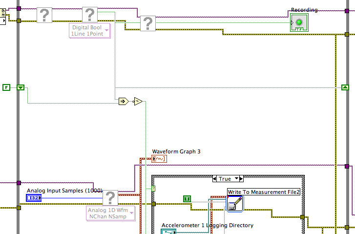
To detect changes in the digital input, you need to compare the current value to the previous. The easiest way to do this is to plug the output of digital playback on a shift register. The Boolean function involves will tell you when a transition has taken place. See the central part of the image below. If you exchange the true and the false case of case structures, you not the inversion function. Look at the help file for more information on what the function actually implies.
You must also change the wiring of the name of input for writing custom file FIle.vi so that the name is automaticlly changed. Depending on what you want the naming system to be, that it can be simple or rather complicated.
Lynn
-
Analog input and contrary to the worksheet
Hello
I m trying to get an analog input (volts of a sensor) and a counter with an encoder. I ve long time looking for a solution and I ve already found some very useful examples that I ve used on the VI (thanks for that
 ).
).The program is very close to what I want, but there are still a number of things that I don't understand (I m very new with labview and I still Don t know exactly what I m).
-J' read in an example here that I should use "Single Point timed material" and use the "wait for next sample clock VI' to get samples always with a period fixed (rate). It's works! Before, I used "continuous sample" and it was a bit jitter. Well, could someone explain to me please what is the difference between continuous and timed, material and how the 'Harware Timed Single Point '.
-My second question is about the string formats that I receive on the loop of the wave. I ve tried with very different formats, but it doesn´t work as I expected. I have a format string like this on the 'Date Format VI': %S % 3u-online seconds with 3 decimals?
And on the format I have on the 'picture to a worksheet VI string' should I used %5.7f to get 5 decimals on the output (spreadsheet file). Why?.
What I m trying is to get the analog input with counter clock (I think I already do), given a graph and a file with lines of 3: 1 °-time with 3 decimals, 2 °-v with 5 decimals (positive and negative) and 3 °-position (positive and negative integer).
Software: Labview 2013, pilot DAQmx 9.8, Windows 7 32-bit
Material: NEITHER 6321 PCIe, Intel Quad 9550, 4 GB RAM
I hope that his undestable, I should learn some English to.
Thank you
Hello
Thanks again for the response. I tried to implement the code as you say, but it's always a mistake to time. I solve it with a timestamp.
The idea of a producer consumer loop was very good. After"a bit", I managed to solve it too. Here's the code.
Thank you
-
Full scale PXI - 6254 DAQmx Analog Input
Hello
I use PXI - 6254 Board to read the analog inputs. Configured channels using DAQmx create Channel.vi with sub parameters.
In the configuration: CSR
Min: 0
Max: 10
Units: Volt
I read the channel using DAQmx Read U16 2D with the sample of 1. I expected below the values.
data of 0 v = 0
10 volts = 65535 data
but it gives 10 volts = 31544 data. Please let me know why.
If I set up the channels with the settings below:
In the configuration: CSR
Min:-10
Max: 10
Units: Volt
He always reads the same values (data 0 v = 0, 10 volts = 31544).
Please let me know, how I can get 10 volts = 65535
Thank you
Hi LVTestek,
The PXI-6254 is not an interval 0 to 10 V input V. The specification of 625 x OR lists the available input ranges:
Entry level of ± 10 V, ± 5 V, ±2 V, ± 1 V, ±0, 5 V, ±0, 2 V, ±0, 1 V...
When you set Min = Max 0 = 10, DAQmx chooses the smaller input range that allows to measure signals between 0 V and 10 V without clipping. On the PXI-6254, the smaller input range that meets this criterion is the range of ± 10 V, where - 10 V corresponds to-32768 0 V corresponds to 0 and 10 V corresponds to 32767.
However, there is an additional complication: ranges entry on M Series devices are slightly wider to accommodate the software calibration. Otherwise, gain of a device could reduce the scope of actual entry, and offset error would move the ends of the effective input range. If the [-10 V...] 10 v] range on your PXI-6254 could be more like [-10.3 V...] 10.4 V]. 10 V is actually to 31544, rather than 32767. On another PXI-6254, 10 V could correspond to a different value of gross / scaleless and 31539 31552.
Another side effect of calibration of the software, is that the data returned by the flavours 'raw' and 'no' to the VI DAQmx Read are benchmarked. The KB explains further: is raw data DAQmx calibrated or chipped?
If you can modify your application to use one of the flavors "on the scale" (F64) VI DAQmx read, which should save a lot of effort. If not, could you explain why your program requires readings without scales/bullies? The right approach depends on the requirements. For example, if you want to save the data in a file and you need to reduce the file size by using raw data / scaleless, configuration DAQmx to save data directly a TDMS file can meet your needs. If you update an older application to work with DAQmx and M Series, a different approach may be more appropriate.
Brad
-
Recent storm electric, internet, lost when I logged in Outlook Express, I lost all my files and folders saved. Is it possible to recover? Thanks for any help.
Two reasons the most common for what you describe is disruption of the compacting process, (never touch anything until it's finished), or bloated folders. More about that below.
Why OE insists on compacting folders when I close it? :
http://www.insideoe.com/FAQs/why.htm#compact
Why mail disappears:
http://www.insideoe.com/problems/bugs.htm#mailgone
About file Corruption:
http://www.Microsoft.com/Windows/IE/community/columns/filecorruption.mspxRecovery methods:
If you use XP/SP2 or SP3, and are fully patched, then you should have a backup of your dbx files in the Recycle Bin (or possibly the message store), copied as bak files.
To restore a folder bak on the message store folder, first find the location of the message store.
Tools | Options | Maintenance | Store folder will reveal the location of your Outlook Express files. Note the location and navigate on it in Explorer Windows or, copy and paste in start | Run.
In Windows XP, the .dbx files are by default marked as hidden. To view these files in the Solution Explorer, you must enable Show hidden files and folders under start | Control Panel | Folder options | View.
Close OE and in Windows Explorer, click on the dbx to the file missing or empty file, then drag it to the desktop. It can be deleted later once you have successfully restored the bak file. Minimize the message store.
Open OE and, if the folder is missing, create a folder with the * exact * same name as the bak file you want to restore but without the .bak. For example: If the file is Saved.bak, the new folder should be named saved. Open the new folder, and then close OE. If the folder is there, but just empty, continue to the next step.
First of all, check if there is a bak file already in the message. If there is, and you have removed the dbx file, go ahead and rename it in dbx.
If it is not already in the message, open the trash and do a right-click on the file bak for the folder in question and click on restore. Open the message store up and replace the .bak by .dbx file extension. Close the message store and open OE. Messages must be in the folder.
If messages are restored successfully, you can go ahead and delete the old dbx file that you moved to the desktop.
If you have not then bak copies of your dbx files in the Recycle Bin:DBXpress run in extract disc Mode is the best chance to recover messages:
http://www.oehelp.com/DBXpress/default.aspxAnd see:
http://www.oehelp.com/OETips.aspx#4A general warning to help avoid this in the future:
Do not archive mail in default OE folders. They finally are damaged. Create your own folders defined by the user for mail storage and move your mail to them. Empty the deleted items folder regularly. Keep user created folders under 300 MB, and also empty as is possible to default folders.
Disable analysis in your e-mail anti-virus program. It is a redundant layer of protection that devours the CPUs, slows down sending and receiving and causes a multitude of problems such as time-outs, account setting changes and has even been responsible for the loss of messages. Your up-to-date A / V program will continue to protect you sufficiently. For more information, see:
http://www.oehelp.com/OETips.aspx#3And backup often.
Outlook Express Quick Backup (OEQB Freeware)
http://www.oehelp.com/OEBackup/default.aspx


Maybe you are looking for
-
"Reload" disappeared from the drop-down 'View' - ask again
Cannot find my question already asked, posted on the forum so I ask again: "Reload" option has disappeared from the menu 'view' drop-down in the navigation bar. I tried all of the following characteristics, as was suggested by a contributor: Reboot w
-
Cannot install new hardware (wireless mouse, ipod) on my Equium M50
Hello I'm a newbie here, I m having problems with my Equium M50-192 don't know when the problem started, but I can not install new hardware have tried to install a wireless mouse and a new ipod, but it will not install the drivers for the latter. Any
-
I've finished, work application LabVIEW 7.1. It is built as an executable file. If I have a long distance user buy the necessary materials, my exe file will recognize the front end and work? Ron
-
LAN/connectivity limited or not
My computer is sailing very slowly when navigating. At the State checking, he said that there is no or limited connectivity. That is what it is?
-
HP DESKJET 2540: Could not print a thing even after test print
Hello I'm looking for gurus who would help me on my printing problems. I had installed the drivers and run the HP Print & Scan Doctor 4 and it saids that my printer is perfectly fine. However, I am not able to print the page to test, or any other doc