NEITHER 9233 Microphone conditioning of signals
Following an update of LabVIEW 2009 Pre - polarised FAT microphones work correctly with 9233 modules OR multifunction data acquisition. (They have been used regularly since 2007).
There is an important distortion of the signal calibrated showing the cutout of the positive part of the trace to higher levels of entry.
Connection from one system to the external packaging of signals MIC shows perfect sinusoid using the same (FAT 40AE) microphone capsule, (BOLD 26CF) amplifier, cable and NI 9233 - we have 2 examples of each element.
The only element that seems common to the fault is the conditioned signal of the NI 9233 following the update of LabVIEW 8.6 in 2009. I tried to change the level of excitement from 2mA to 4 and 8 with no benefit (specification of FAT said 4mA nominal 2-20 MA). I noticed that there are a few changes in the terminal configuration option dialog, but after trying to change this, it is the only viable option "nickname".
The determination of sources of external power and excitement for the microphone is not an option for practical reasons, but it does not restore the original function.
Is there a change documented 9233 with LabVIEW 2009 service or is there a simple solution to this change in behavior?
Thank you.
The interests of other users, it seems that the microphone needs a little more excitement to 114dB, where cut when it is used with the 9233 which can only provide 2mA. The installer works fine at 94dB, where 2mA is enough excitement. There are no errors appearing in the software, since it is a hardware limitation.
Kind regards
Michael S.
Technical sales engineer
NEITHER UK & Ireland
Tags: NI Hardware
Similar Questions
-
conditioning of signals using RTD
I want to know on how we will design the circuit of signal conditioning for RTD... using 3op - amp instrumentation amplifier... If know something about it so please tell me... as soon as possible...
I like to draw circuits like this, although it is almost always cheaper to buy an amplifier for instrumentation of TI or announcement that in order to pay me to do.
You can ask specific questions we don't need to guess what you want?
Lynn
-
NEITHER 6229 let me power Signal in NOR 2503
Hi everyone, I'm feeding a train of pulse (Signal of PFI P2.0) my NI 6229 map to my card to MUX NI 2503. I pass the MUX of topology Quad 6 x 1 2 son. My pulse PFI train signal goes to COM1 + and I am firm MUX_CH6 + to use for external signals. This signal will be on MUX_CH6 -? Will it be a reference to the ground or no connection? I know that for a signal from the outside in the MUX and then MUX6 + = SIGNAL HI and LO-MUX_6 SIGNAL = but how about signals leaving the MUX and then power external circuits. What does MUX_6 have on this subject?
Thank you very much!
COM - is not bound by default to what whatsoever. If you only have a PFI line in your COM +, then your COM-, and later MUX_CH - will not have any signal on it (it is not related to chassis ground etc. so it's just a wire connected to nothing).
-
Hello guys,.
I have a general question regarding the units of packaging such as the USB-9263 analog output signal. If I can use it instead of data acquisition to provide an analog voltage output?
Thank you
ELA
Yes, the 9263 can provide 4 output channels analog voltage (+/-10 v range) with up to 1mA of current drive. Looks like: it refers to the short circuit of conditioning of signals and some protection against overvoltage. Link below is the User Guide:
http://www.NI.com/PDF/manuals/372406b.PDF
-AK2DM
-
Multiplexing of signals microvolt and conditioning of the right signals
Hello
We have 22 signals in our system. We must be able to measure any subset of these 22 signals. Usually, we carry out a number of measures IV 4points of separate devices on a SUT (sample to be analyzed). Two of the 22 signals may represent the pair of voltage measure 4-point IV, depending on how it was KNOWN is bonded. The level of the signal of tensions is in the 100s in the uV range and I need a precision as much as possible, so the unit or same sup - uV numbers. So far, we had all the 22 signals connected to a box (selfmade) acting as a distribution point, where a connector (SMB) is available for each signal. We then manually choose which two of the 22 that signals will be connected to a differential amplifier silent instrumentation (also selfbuilt), according to it was KNOWN patterns of liaison. The amplifier with a gain of typically 1000, returns the signal to an acquisition card. The current (excitation) is read separately.
There is a problem with that. We need to manually switch the connectors in the distribution box to select a different device on it was KNOWN and flows to the amplifier. This is not good for a number of reasons that I can't go here.
Therefore, I would like to multiplex these 22 signals to several outputs (for future scalability) who will be wired for the conditioning of signals. There is no manual connection/disconnection of these signals in this way. The first question is: can a matrix switch or multiplexer be used to route signals reliable microvolt? If so, then what kind: electromechanical, Reed relay or a transistor? Is the thermal EMF in the specifications of multiplexer/matrix relay just a lag, or is - that noise?
The second question is: what card/signal acquisition solution (so no selfmade equipment and legacy) products OR only using the same line that the matrix/mux can reach 1uV accuracy of treatment? For us, offset offset is not a problem since we measure the device in 2 quadrants and later cancel it in the software but the noise (and get the accuracy) is important. Our amplifier has a background noise of 3nV/sqrtHz and a bandwidth of 15 kHz. The system to replace must be comparable. I have the choice between:
- the SCXI based ones, instrumentation isolation (4ch) 1121 or 1122 amplifier modules (16 channels), with a ground noise that I calculate 20 and 30nV/sqrtHz respectively. They already have some functions of multiplexing btw.
- the PXI 628 x with a background noise that I calculate through 10nV/sqrtHz
- the PXI 446 x with the noise floor low 8nV/sqrtHz as stated in the technical data sheet
Module 4-way universal 24-bit NI 9219, who works with 2 samples per second has a very low noise total, but at a very low sampling frequency and I can't consider comparable to what we have now. In addition, the system must be able to have a few kHz bandwidth for dynamic action in the future.
Y at - it any other ideas?
Greetings
Aleksandar Andreski
-
Compact Daq or Rio measurement signal and datalog
Hello
I'm in a project to create a diagnostic for an offshore wind turbine generator system.
So I have to choose a material acquisition and make the basic operations with the measured signals.
The equipment has to work without being connected to a PC, write the data in the internal memory, and then send it via ethernet.
The CDaq and the controller chassis is cheaper than CRio, but she would work without a PC (with the exception of couse the stand-alone version that is overpriced)? Is it possible to add memory via USB to a CDaq (for datalog)?
Hello
If cDAQ standalone chassis is more than your budget, then cRIO is the right/only way to go. The good thing is that they share the modules C-series real connectivity and conditioning of signals is the same. Youneedtohavesomeformoflocalintelligence/processingpowertoevenperform the taskofwritingdatatoaflashdrive "simple."
This is a technical presentation online that might interest you: measures and monitoring in Offshore Applications
Let me know if you want me to make a connection with your local technician to NEITHER.
-
How to continually take and record waveforms with neither 5102
a machine generates waves sinusoidal time randomly. I want to permanently take and record waveforms in 10s by NI 5102.
How to do?
Thank you very much!!
Thanks for the review! but this isn't a supported NEITHER.
I record signals by this method.
and the promble news is that different sampling frequency, the different wavelength. for example, when I put the sampling frequency is 4 k, the wavelength is 12 seconds if the sampling frequency is 10 k, the wavelength is 8 seconds the signal under test 1 k, the time constant is 10000.
now, I save waveform to 10 sec. What is the best relationship between sampling frequency and the time constant?
-
Filtering of noise signal to acquire sound
On the labview 2011 I'm aquireing a sound of a microphone and the signal is chart and I can see the time 0 a small peak every time if it is solid or not and I have no idea where its origin or how to get rid of.
After manipulation of the signal to try to get rid of noise signals and background this signal as well as my signals wanted to turn into a huge spikes which is a problem because I am trying to use it to acquire the location of a sound source by the time between these points later, when I have more than micophones but it keeps be wrong this time epi 0 as a sound when there is an error
any ideas?
What is a single-point peak? If so, it's just to say the part of the program to ignore the time value = 0 (or replace with the value for the second time).
Cameron
-
I suspect I already know the answer to this question:
I have an PXI-6224 M-series data acquisition card and a terminal of the SCB-68 block and want to take action using a bunch of 4-wire RTD. Is the power to the power source for these measures 6224, or is - not possible with the hardware I have?
I know that NEITHER you propose other solutions to my problem: I am interested to know if I can do these measures with the device that I currently have on site.
Thank you!
Hello Jeffrey,.
You have two options here, but it doesn't look like you need some hardware.
The SMU-4357 built conditioning of signals, but it will not work on the chassis curent you have:
http://sine.NI.com/NIPs/CDs/view/p/lang/en/NID/210596/
We also have an option with the NI 9217 cDAQ, but once, it gets you into a different platform:
http://sine.NI.com/NIPs/CDs/view/p/lang/en/NID/208804
We used to have an option that we sell no more - the SC-2042RTD. If you are lucky and have one of them on hand so here's some info:
http://digital.NI.com/public.nsf/allkb/4FF2C0F8D11B99B486256F4C006DCEA0
You can also use these two elements in conjunction with eachother with your current PXI card:
http://sine.NI.com/NIPs/CDs/view/p/lang/en/NID/12311
http://sine.NI.com/NIPs/CDs/view/p/lang/en/NID/10778
Finally, you could get an SCXI chassis and drop them in:
http://sine.NI.com/NIPs/CDs/view/p/lang/en/NID/201609
Thank you
Joel C
Technical sales engineer
National Instruments
-
Hi all!
I have a HBM (LVDT) inductive position transducer. WA series. I need a PCI card to read this sensor. I took a quick glance at this link http://zone.ni.com/devzone/cda/tut/p/id/3638 , but I'm looking for a simpler solution in the form of a pci card.
Any suggestions?
All the best.
Gabriel Oliveira (Novo Hamburgo / BRA)
Hi Gabriel,
Doesn´t OR have a card PCI-conditioned to acquire signals LVDT, you will need conditioning of signals or you can both a system NI SCXI to acquire the signal of an LVDT.
You can try to speak with one of our technical sales representative.
National Instruments Brazil
(55-11) 3149-3149
Kind regards
Abel
OR Brazil
-
This module which can measure the pressure of the pressure transducer and the strength of the load cell other than analog or 9219@universal?
Hi Darul,
It is best that you ask the question in another forum this is the forum of academic hardware products. Since you mention NI 9219, I guess that you already have a Compact DAQ chassis. If you want to measure the scale you can use NI 9219 or NI 9237 (http://sine.ni.com/nips/cds/view/p/lang/en/nid/208791). NEITHER 9237 can connect to a half-bridge or full-bridge sensor. So, you will need to check the charge of the specification of the cells, which are typically full-bridge sensor.
For pressure sensor, this will depend on the conditioning of signals required for the pressure sensor. Thus, you will need to provide the specifications of pressure sensor before I suggest any module. Usually a pressure sensor will require type of PEAK conditioning of signals, and for this, you can use the NI9234 (http://sine.ni.com/nips/cds/view/p/lang/en/nid/208802). A pressure sensor comes also equipped with the transmitter (which is a signal conditioning module) and the output voltage (usually 0 - 10V) or current (4-20 MA). For this type of pressure sensor, you can use NI 9201 (http://sine.ni.com/nips/cds/view/p/lang/en/nid/208798) for the measurement of the voltage or the NI 9203 (http://sine.ni.com/nips/cds/view/p/lang/en/nid/208805) for current measurement.
Rando
-
Problem of Earth / Circuit Design
Dear community,
in advance, I thank you, I hope this is the right place to ask this kind of question.
I would like to design a very small preamplifier pre - one preamplifier because it is mounted on the head of the insect to behave and a later analog frontend for the conditioning of signals and an additional gain. Unfortunately, I have major problems with respect to the ground.
Please see the attached PDF file:
(1) the preamplifier must be supplied with a supply separate power source such as a battery. as I need a dual power supply, I would use just two batteries connect them in series and take right in the middle like that is usually connected to the GND pin 0V? so in this case I would connect the preamplifier power supply 0V to the same connection as REF?
(2) the shield of the cable from the head to the preamplifier should be connected for the Earth also the chassis of the preamplifier. In this case, I would like to use the net power to which I have access to the preamp power which is made with normal voltage rectifier/regulators (I know that there are missing parts
 )
)the 0V of the preamp power supply should be linked to the mass of the filter etc. steps that finally end in the GND to my A/D card of NEITHER? right?
(3) now, I have to admitt that I did not the differential amplifier in scene myself and it actually makes me a problem because here's an op amp used to excite the input of the differential amplifier and this op amp is that related to these TWO grounds: the virtual mass to the head and the GND AI through the op amp. I unfortunately have no idea what this op amp is doing?
So, it would be great if someone could tell me if my grounding considerations are right especially with (AI GND) and what does the op amp out and if I should use referenced asymmetrical pattern of NRSE.
ManyManyMany thanks to you all,.
Yours,
Prefrontal
Thank you!
Kind regards
Prefrontal
-
Logic pro motu audio interface
Someone has trouble with Motu 4pre after upgrade to El Capitan? I have no signal: alert the Motu 4pre in Logic Pro. All levels of finish on the CueMix interface return to 0 and all the channel input levels return to - inf dB regardless of what I do. I reinstalled the Motu software, but that did not work. Microphones operate and signals to inputs XLR 4pre seem to agree.
You have the latest drivers for the 4pre?
v1.6.68717 | February 11, 2016?
-
Magnetic sensor to the top of analog frequency AC for Turbine flow meter measurement
Hello!!
I use the following hardware configuration to measure a flow meter flow turbine.
Material: 1000 SCXI Chassis
SCXI 1102 voltage input module
SCXI-1303 terminal connection block
Flowmeter: output signal is the frequency of the alternating current (30mv peak-to-peak). Sensor is a magnetic sensor type.
I tried to convert the signal of output voltage in the area of frequency using the FFT, but I get the wrong data.
I wonder if anyone can suggest good troubleshooting techniques so that I can understand what is mess up my position or my technique of measurement in labview itself will not completely? (From my understanding I think that I can measure the frequency of the ac voltage signal generated by the sensor of the FFT. By measuring the frequency I can calculate the water flow)
I am aware that a potential cause might be the ground loop in the system. The signal is based solely on the SCXI-1102 with factory default bias and pullup resistior network. I see no other reason reading wrong or fault in my measurment. Also the flowmter is brand new and there is no risk of damage to the sensor.
I'm sorry if I'm missing out on any important detail to answer that I am relatively new on the techniques of data acquisition.
Thank you
Concerning
Aditya
It's conditioning of signals... and that's what you want to do, so it's not so far
And if your signal about 30mV Ridge to Ridge, it fits perfectly in the beach of crete to 200mV Ridge... I wouldn't say no need of amplification... the + 100mV is not a minimum of signal, this is the maximum signal in this range
Hang it up, take a measurement in single channel mode with one all 10kSPS sample rate take 100ms (1000points) and feed in single tone detection...
display with a graph of signal, stop the vi, in the rigth diagram, click the graph icon and create a constant, save that in a vi and post here if you need help in signal processing
-
Using instrumented hammer model PCB 086D 50 with the NI9234 module and chassis OR cDAQ 9188
Hi all
I need to try to shock with a PCB 086D 50 instrumented hammer hammer. I use the chassis OR cDAQ-9188 with the NI9205 and NI9234 modules. The hammer is connected to the NI9234 and accelerometers are connected to NI9205.
When I test the modules in SignalExpress I get very good results for the dog, but the accelerometers are ok. Also, if I am controlled the hammer OR Max where I have the option to activate the IEPE the result is ok. In SignalExpress, I couldn't find the option to activate IEPE.
I have no experience using software, but I started to learn. Does that mean that I need to program the system for my setup in LabVIEW? Also, the installer of the equipment makes sense, the modules that I plugged on the cDAQ can be used simultaneously? Should I have the additional device in order to use the hammer with cDAQ 9188?
Thank you very much
Emina
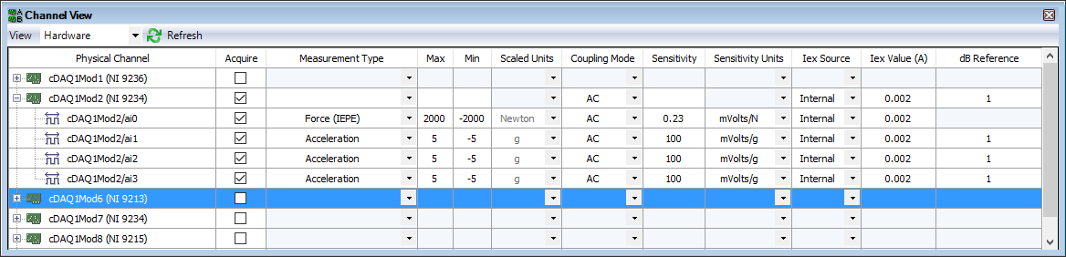
You can enable IEPE in SignalExpress. Here is a configuration for a single power hammer and three accelerometers a 9234-related.
You don't mention the model for accelerometers. They are also the IEPE sensors? If so, have what conditioning of signals you added before the 9205?
The Assistant Sound and Vibration (built on SignalExpress) contains an example of Impact Test. The Sound and Vibration Toolkit comes with a sample project for the impact test. With free evaluation period, go ahead and look at how one of these examples is implementing the configuration and the triggered acquisition.
Maybe you are looking for
-
Hi allI have a problem that is I have already installed windows XP then I installed all the drivers for SD card located on the CD after the restart but the laptop even, the card does not work so I installed the latest version of the Toshiba site but
-
5.1 Windows search fails to find files
I keep the images in folders by year like 2008. Looking for a 2008 find nothing. This folder is located on the backup drives: F: and G:, H:, but Windows Search does not find it. Nor it is images in the folder. That is what it is? How can I force
-
Original title: How can I fix external MSI? When I try to download the updates, the error message says there is a problem with the external Setup program and it must be closed. Updates will not be installed. Anyone know how to solve this problem...
-
BlackBerry 7 Webworks Documentation
Hi guys Could someone point me in the direction of Blackberry 7 or earlier Webworks documentation. I had a quick glance, but I seem to keep coming back to the Blackberry Webworks 10 docs. See you soon Marcus
-
"C:\Users" folder is shared when you share a folder in the directory?
So everyone seems familiar with this problem, but has anyone seen an answer yet? I've been whinging about it since the launch of Vista, but I am yet to see a resolution that does not involve a work around. I was surprised to start seven RC and find