conditioning of signals using RTD
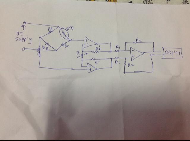
I like to draw circuits like this, although it is almost always cheaper to buy an amplifier for instrumentation of TI or announcement that in order to pay me to do.
You can ask specific questions we don't need to guess what you want?
Lynn
Tags: NI Hardware
Similar Questions
-
How can I use the USRP to record a signal using its two RX ports simultaneously?
Hello.
I am trying to record a signal using two antenna cone. The reason that I need two antenna to cover the bandwidth (DC - 6 GHz). a single antenna covers DC - 300 MHz and the other covers 300 MHz to 6 GHz. so I need to use two RX port of USRP at the same time to record the signal. I have two questions:
1. is this all USRP market capable of covering this frequency range?
2. is it possible to use the two RX port at the same time to the signals of the records I described? If this is not the case, how can do?
P.S. I have two NI2920 USRPs and two USRPs N210 in my lab.
Thanks in advance for your time.
Sam.
Hi Sam,
To answer your first question, the USRPs you can reach the bandwidth you want. There is not a USRP, to my knowledge, that can reach this range in a single device.
Also note that you can only use RX convened for two different ports at the same time using LabVIEW and the pilot of the USRP. If you want to use the two lines of RX, you will need to run a session with a single line, close the session and then start a different session for your second RX line.
-
Reading of analog signal using DAQPad-6016
I'm reading an analog signal using DAQPad-6016. An entry is on the ground, the other is Vdc. I can't operate at MAX and I'm confused becaue MAX alone gives me an option for differential reading, but the list of pins give enough information on how to connect in a different way. Is there a reference as well?
Hello, Bernadette.
This link should have what it takes to equip themselves properly: http://www.ni.com/gettingstarted/setuphardware/dataacquisition/analogvoltage.htm
After that you have put work in place, specifically see step 11 for check the connections of the device.
I hope this helps!
-
NEITHER 9233 Microphone conditioning of signals
Following an update of LabVIEW 2009 Pre - polarised FAT microphones work correctly with 9233 modules OR multifunction data acquisition. (They have been used regularly since 2007).
There is an important distortion of the signal calibrated showing the cutout of the positive part of the trace to higher levels of entry.
Connection from one system to the external packaging of signals MIC shows perfect sinusoid using the same (FAT 40AE) microphone capsule, (BOLD 26CF) amplifier, cable and NI 9233 - we have 2 examples of each element.
The only element that seems common to the fault is the conditioned signal of the NI 9233 following the update of LabVIEW 8.6 in 2009. I tried to change the level of excitement from 2mA to 4 and 8 with no benefit (specification of FAT said 4mA nominal 2-20 MA). I noticed that there are a few changes in the terminal configuration option dialog, but after trying to change this, it is the only viable option "nickname".
The determination of sources of external power and excitement for the microphone is not an option for practical reasons, but it does not restore the original function.
Is there a change documented 9233 with LabVIEW 2009 service or is there a simple solution to this change in behavior?
Thank you.
The interests of other users, it seems that the microphone needs a little more excitement to 114dB, where cut when it is used with the 9233 which can only provide 2mA. The installer works fine at 94dB, where 2mA is enough excitement. There are no errors appearing in the software, since it is a hardware limitation.
Kind regards
Michael S.
Technical sales engineer
NEITHER UK & Ireland -
Accelerometer (voltage) of the signals using the module NI6361 (PXI)
Hi guys,.
I posted this question once again, but I still have problems with the acquisition of data. I'm acquiring a voltage signal by using an accelerometer module and single voltage NI6361. I would like to set up the accelerometer to measure a range of signal between + / 5000g.
The accelerometer sensitivity = 0,516 mV/g where
1 g = 0,000516 Volts or
1938-g = 1 Volt or
5000 g = 2.58 Volts
-J' left the signal conditioning with +/-10 Volts (despite the fact that there is another option value +/-5 Volts as well)-please see attached pdf
-I entered the units sensitivity to g
-J' put labview to measure a signal between +/-10 Volts to the single a complete axis accelerometer.
-An oscilloscope was related to the card, and she won the same vertices with the LabVIEW. -Please see attached pdf
-By knocking gently on the accelerometer, the recorded signal was 400 mV = 0.4 V where he gives an acceleration of 775g.
-L' accelerometer is also fixed on the ball for a shock test fell from a distance of 50 mm. The recorded acceleration was 4000g which is quite high for such a small distance. I expect an acceleration of about 200g of 2 to 4 meters according to some documents as well.
Can you please give me any help on the way in which the parameters are specified correctly between the accelerometer and the coupler? I'd appreciate it highly if you can correct me if anything of the above statement is false. I have attached a PDF for your convenience.
Kind regards
Since gain is the scale factor for tension, you must divide your results by the gain.
g = voltage / (sensitivity * win)
-
Satellite U400 - no Signal using the LCD TV HDMI connection
I connected the laptop to my Phillips TV with hdmi-hdmi cable.
The first few days everything worked fine.Yesterday, when I turned on the TV, the laptop screen flickered.
The image on the TV shows the first seconds, then becomes a blue screen and displays the message "No Signal".
What is the problem?I have to support by phone, call, communication is cut off in a minute.
Sorry for my English, I'm from the Russia.Hello
I m not fine what could be wrong, but it seems that there is no signal from the HDMI port.
I think you should check the basic thingsFirst set the default BIOS (press F10 BIOS and save the changes).
In addition to use the FN + F5 key combination to switch between the display of the computer laptop and external displayThe graphics driver must be updated or reinstalled as well
-
generation of two complementary pwm signals using myrio
Hello, im working on a project and I need to generate two complementary pwm signals (when we go to 1, the other goes to 0) using myrio.
the problem with the blocks of myrio pwm is that when you set the market factor, the signal always starts with its high value. Can someone help me please?
Hello
You can create a Boolean square signal with chosen service and frequency cycle, create its opposite with makes NO sense and then send both signals via Digital Out vi (myRIO/Default/Digital Out) to two different outputs.
Best regards
-
Variation in the strength of RF signal using NI USRP 2920
Hello
It is possible to vary the intensity of the signal RF uses USRP 2920? If so, please guide me for this. I would like to transmit the RF signal from 900 MHz with value different GCQ (shows the power of the signal)
Thank you and best regards,
Gowtham Blais
Vindex Hi,
Unfortunately, the USRP is not a device calibrated, you cannot specify an output level of absolute power. However, you can set the gain of the device. The output power varies according to the frequency and bandwidth of the channel that you create, so it is recommended to use a power meter to check the levels of power absolute. The gain is not as guaranteed to be linear. Official warning is formulated as follows:
The USRP devices are not calibrated. The value of the gain does not represent an absolute gain and has no linear behavior. Different devices have different gain for different carrier frequencies curves. You may need to experiment to determine that the right setting for your application of gain.
With this in mind, you can set the gain (in dB) using the niUSRP Signal Configure VI, which is in the palette of the USRP API Tx in LabVIEW.
Kind regards
-
USB-6009 slow output signals using SignalExpress - error 200077
We have a Council of USB-6009 and Signal Express version 3.5.0
We want to generate low-frequency, analog and digital outputs to simulate some slow movement process.
We have created the signals and their generated as output, put when we RUN the project, we get error 200077, which seems to indicate that we must use On Demand distribution of signals.
If we choose On Demand, then the generate DAQmx says we have a missing entry.
So, what method should be used with the slow USB-6009 to generate box (.01Hz and slower) analog and digital outputs?
These are 2 of the projects, we tried - using On Demand, N samples, continuous, internal, and external triggering etc..
Thanks adavance for your help...
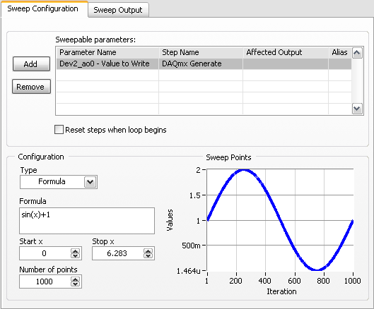
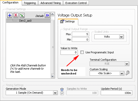
Welcome to the forums of Steve,
I have good news for you. I played a bit with the sweep and actually got a code facing up to generate a slow signal. I went and tested it with the 6009 and he was able to run without any errors. I joined here, but if you have to open (or anyone else in the future), here are some screenshots of how it works. If this works, feel free to make the forum as resolved while others can locate a solution a little easier in the future.
Scan Configuration:
DAQmx Config:
-
Digital synchro recording signal using PFI0/PFI1
Hello
I try to sync data between an instrument NOR cDAQ-9188XT acquisition and a 3rd party.
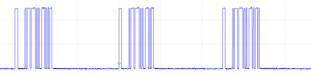
The instrument of 3rd party kicks out a digital synchronization signal which consists of a short pulse whenever it samples followed by a series of pulses coding a 32-bit integer (see image - signal synchronization for 3 bags). This integer is the serial number recorded with each packet of data. Samples of instrument to a pace of 2 kHz, so the pulse + whole occurs every 0.5 ms and by my rough calculation, each bit of the integer lasts 5 µs.
The cDAQ-9188XT will record a series of analog channels by using LabVIEW, and I wish to record this signal to synchronize with the analog channels, so I can sync the two sets of data in post processing. There is no spare slots in the cDAQ so I can't use a digital I/o module and I believe that the frequency of sampling of my analog channels will be too weak to pick up the signal from sync.
The cDAQ-9188XT has two BNC connectors on the frame that correspond to lines PFI0/PFI1, I would like to know if it is possible to use a PFI line to record this signal of sync?
See you soon.
Pat.
Think about it once again, if you're happy with the post-processing of the data, then you can get in with the straightforward acquisition code (maybe start with an example of the semi buffering period ). This will give you a picture of the down time of the signal that then you need to decode in the 32-bit number.
Best regards
-
Hello
I want to generate signals with my USB-6211 from a prepared file in advance, so I have a file full of sampling points and you want to generate a signal with this file. The file can achieve big enough. So I need to find a way to partially fill the generator with samples...?
Anyone?
Best regards
Thijs
Hello Thijs,
What file do you use? Excel? TDMS? txt? or others?
I guess you wrote your samples in a normal txt file.
To do this, you can read in your worksheet (if its only data without columns, which are not serious) you can use the worksheet File.vi reading
This VI reads all the data that you specify (how many lines, shift etc.) after that, you can simply set your table with the normal array functions and give these data
to your task AO.
Let me know if this was helpful, or if you would like more information.
Kind regards
Markus
-
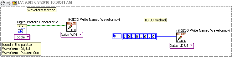
How to generate signals using NI - HSDIO.
Hello
I need to create two signals different pulse square. I don't know how to set their frequencies, number of cycles and FRP using NOR-HSDIO.
Thank you!!
You must create a set of data to send to the HSDIO. It only builds what you send to it. Suppose you want to produce a square on one channel wave. Implement the HSDIO for right channel, trigger, timing, etc. Look at the function HSDIO write nominated Waveform. It says name of waveform, but you can use the polymorphic selector (the area under the function) to select other types of data outside of the waveform, i.e. a table 1 d of numeric (U32, U16, etc.). You must create an arry of data that would be akin to a square wave. Or you could use the input waveform and create a square wave.
The simplest is the waveform because Labview waveform generator functions available. See the image below. If you want to use table 1 d, construct you a table or alternation of 1 and 0 to produce a square wave. The image below is only a partial code. Need to add the rest of the installation HSDIO functions.
-
Manchester in transmission/reception of signals using the digital output of the PCI-6224
How a manchester signal can be sent and received using the OID of the pci card 6224?
I want to create a signal NRZ manchester on a digital output channel and then have the possibility to receive and interpret the same type of signal on a digital input channel.
Any help would be greatly appreciated.
Hi VJohnson,
You might find this post of discussion forum useful.
Looks like LabVIEW has not Manchester coding/decoding built, but do able in your VI by replacing all the elements with the corresponding elements of two and using double the speed of transmission as your clock frequency.
Thank you
Scott M.
-
How the ND_SCANCLK_LINE signal used in DAQmx? It is complete Hold event?
I have moved an old application (using the PCI-6013-OR map) to DAQmx recently, but have some difficulty working. When starting, the signals are configured as shown below.
Select_Signal (1, ND_PFI_2, ND_IN_CONVERT, ND_HIGH_TO_LOW);
Select_Signal (1, ND_SCANCLK_LINE, ND_SCANCLK, ND_LOW_TO_HIGH);I've done the migration as shown below.
Select_Signal (1, ND_PFI_2, ND_IN_CONVERT, ND_HIGH_TO_LOW);
DAQmxExportSignal (TaskHandle, DAQmx_Val_AIConvertClock, "/ Dev1/PFI2");
DAQmxSetAIConvActiveEdge (TaskHandle, DAQmx_Val_Falling);Select_Signal (1, ND_SCANCLK_LINE, ND_SCANCLK, ND_LOW_TO_HIGH);
DAQmxExportSignal (TaskHandle, DAQmx_Val_AIHoldCmpltEvent, "/ Dev1/AIHoldComplete");
DAQmxSetExportedAIHoldCmpltEventPulsePolarity (TaskHandle, DAQmx_Val_ActiveHigh);But my application displays the data in the form of two samples shifted left. I guess that the acquisition has been delayed.
I do correct migration or is there something different in the DAQmx?Documentation OR that I get confused whether ND_SCANCLK_LINE or AIHoldCmpltEvent sample clock. Or is this sample clock?
What is the SCANCLK Signal, and how to use it?
Hope this helps
-
I need photo stock for communication online for a society of plastic surgery. Use the faces and the recognizable body parts?
What are the conditions? What plan I have in case I can use photos?
I would really like to chat with someone from Adobe, but I couldn't find the option.
Thank you!
... AND you can find it too https://helpx.adobe.com/stock/faq.html > Common Questions, Adobe Stock > Stock of Adobe for companies
If necessary and for other issues, click on the http://helpx.adobe.com/contact.html 'until you get to 'cat'. If it is 'open' (ago opening hours) Please use it, I personally had the best experiences. I quote Adobe Preran employee: the chat button is enabled as soon as there is an available agent to help.
Hans-Günter
Maybe you are looking for
-
When we go up to all in the Apple box everything is there except presto
We have a 100H 7 Bravia TV Sony 40 W series. We have an Apple TV (3rd generation) - box and the remote control with Telstra as our service provider. We want to get Presto, but when we go to the whole upward in the Apple box everything is there except
-
MacBook Pro (retina, 13-inch) screen resolution
I have a MacBook Pro (retina, 13-inch) running Yosemite. I'm QA test web pages and I need to determine what my screen (in pixels) resolution to report bugs to the development team. How do I know what's on my screen resolution?
-
Why can't connect me to the server when I get the notifcation to update Firefox?
Periodically, I get a notification that there is an update for Firefox, and when I click on the download button, a status bar appears, but my computer cannot connect to the server.
-
Validation of a tabular presentation online using Ajax
I am trying to create a java script confirm the dialog box in the form of...When the user attempts to insert a new line with even Ename and job that already exists in the table, and once they press the button for treat, I check via ajax if data exist
-
Video RAM adjustment on Lenovo R61e
Hi all I have a Lenovo Thinkpad R61e. I installed 2 GB of RAM, and I would like to set up shared video RAM. I know it's automatic, but I would like to first of all he way I want. I looked in my BIOS, and there is no setting to change the video RAM se