NEITHER 6229 let me power Signal in NOR 2503
Hi everyone, I'm feeding a train of pulse (Signal of PFI P2.0) my NI 6229 map to my card to MUX NI 2503. I pass the MUX of topology Quad 6 x 1 2 son. My pulse PFI train signal goes to COM1 + and I am firm MUX_CH6 + to use for external signals. This signal will be on MUX_CH6 -? Will it be a reference to the ground or no connection? I know that for a signal from the outside in the MUX and then MUX6 + = SIGNAL HI and LO-MUX_6 SIGNAL = but how about signals leaving the MUX and then power external circuits. What does MUX_6 have on this subject?
Thank you very much!
COM - is not bound by default to what whatsoever. If you only have a PFI line in your COM +, then your COM-, and later MUX_CH - will not have any signal on it (it is not related to chassis ground etc. so it's just a wire connected to nothing).
Tags: NI Hardware
Similar Questions
-
How to choose destinations for counter/timer signals in NOR-DAQmx?
In the document M Series DAQ
M series user manual
622 x, NI 625 x and the materials NOR x 628
M series user manual
July 2008
371022K - 01appears on page 7-30:
Counter/Timer default pinout
By default, NEITHER-DAQmx routes counters/timers and outputs inputs to the PFI pin, shown in table 7-4.
Table 7-4. 68 peripheral pins by default Counter/Timer pines NOR-DAQmx
Counters/timers fail-safety connector 0 PIN (name)
0 2 CTR (PFI 12)You can use these default settings or select other sources and destinations for the
counters/timers of NOR-DAQmx signals. Refer to the connection counter signals
in the NOR-DAQmx help or the help of LabVIEW in version 8.0 or later for
more information on how to connect your signals for common counter
measures and generations.I couldn't find any hint to the appropriate command of DAQmx in the "NOR-DAQmx C reference Help" to select other destinations for counter/timer signals in NOR-DAQmx.
Please can you tell me the DAQmx command right? Thank you very much.
I use the NI USB-6259 M material Series DAQ, BNC end unit.datafriend,
If I remember correctly, you can "free" the output terminal of default counter by calling DAQmxSetCOPulseTerm and passing an empty string in the 'data '.
Hope that helps,
Dan
Edit: You can also set this to any other valid terminal (IE... "Dev1/PFI0") and to send the output to.
-
NEITHER 9233 Microphone conditioning of signals
Following an update of LabVIEW 2009 Pre - polarised FAT microphones work correctly with 9233 modules OR multifunction data acquisition. (They have been used regularly since 2007).
There is an important distortion of the signal calibrated showing the cutout of the positive part of the trace to higher levels of entry.
Connection from one system to the external packaging of signals MIC shows perfect sinusoid using the same (FAT 40AE) microphone capsule, (BOLD 26CF) amplifier, cable and NI 9233 - we have 2 examples of each element.
The only element that seems common to the fault is the conditioned signal of the NI 9233 following the update of LabVIEW 8.6 in 2009. I tried to change the level of excitement from 2mA to 4 and 8 with no benefit (specification of FAT said 4mA nominal 2-20 MA). I noticed that there are a few changes in the terminal configuration option dialog, but after trying to change this, it is the only viable option "nickname".
The determination of sources of external power and excitement for the microphone is not an option for practical reasons, but it does not restore the original function.
Is there a change documented 9233 with LabVIEW 2009 service or is there a simple solution to this change in behavior?
Thank you.
The interests of other users, it seems that the microphone needs a little more excitement to 114dB, where cut when it is used with the 9233 which can only provide 2mA. The installer works fine at 94dB, where 2mA is enough excitement. There are no errors appearing in the software, since it is a hardware limitation.
Kind regards
Michael S.
Technical sales engineer
NEITHER UK & Ireland -
DAQ traditional and generator of signals of NOR-5401
We have an older system using a signal generator of NOR-5401 (S/N 183962E-40) that runs with FGen 1.5.1 and 7.1 of NOR-DAQ
We just bought an another NOR-5401 (S/N 192888 A - 01) to install a second system. However, it does not work with the software. The software uses traditional DAQ. If I look in MAX, the NOR-5401 on the new system only comes in the DAQmx instruments. On the old system, the NOR-5401 is available as traditional DAQ.
If I install an earlier version of the FGen (2.0 is the oldest, I can find) and NOR-DAQ 7.1 then the PC does not find a driver for the new OR-5401 at all.
Should what versions of FGen and NOR-DAQ I install to make it work?
Kind regards
Keven.
-
NEITHER 6229 Analog channel to generate the current
Hello
I use PXI-6229 to generate values of current analog output channel, but I get the following error:
"Physical channel selected does not support the selected property. Select a channel that supports the property, or select a property that is supported by the selected channel"
I tried with all 4 channels of analog output: ao0, ao1, ao2, ao3, but I got the same error with all. Also, when I run the examples OR to
'CVI\Samples\DAQmx\Analog Out\Generate Current\Cont Curr Wfm - Int Clk Gen' location, I get the same error.
Kindly let me know the solution for it.
Thank you
Priya.
Outputs analog 6229 are sources of tension - not a current source constant.
-
Missing VIDEO signals for NOR-5762-(02)
Hello
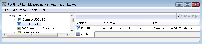
I installed 15.1.1 FlexRIO, and I use it in LabVIEW FPGA 2013.
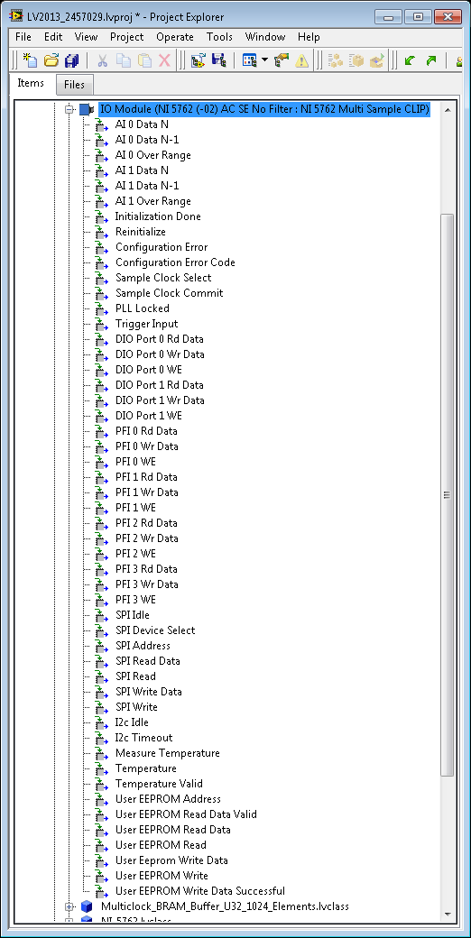
I am trying to program the 5762 using the multi-sample CLIP:
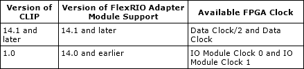
\Shared\FlexRIO\IO Modules\NI 5762\1.0.0\V5\NI5762MultiSampleClip\Ni5762MultiSampleClip.xml. By the November 2015 FlexRIO help, I think I'm supposed to use 'data clock/2' for IO nodes:
However, there no such signal in the signal list when I add the CLIP:
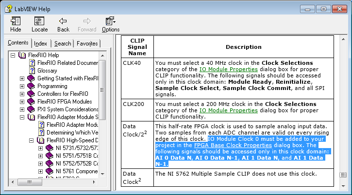
So, I followed what are probably mistakes typing in help FlexRIO next to the data signal clock/2 who say, 'IO Module clock 0 must be added to your project in the dialog box properties of the clock of basis of FPGA. The following signals shall be accessible in this area of the clock: I 0 N data, HAVE 0 N-1 data and HAVE 1 N N-1 AI 1 data data. » :
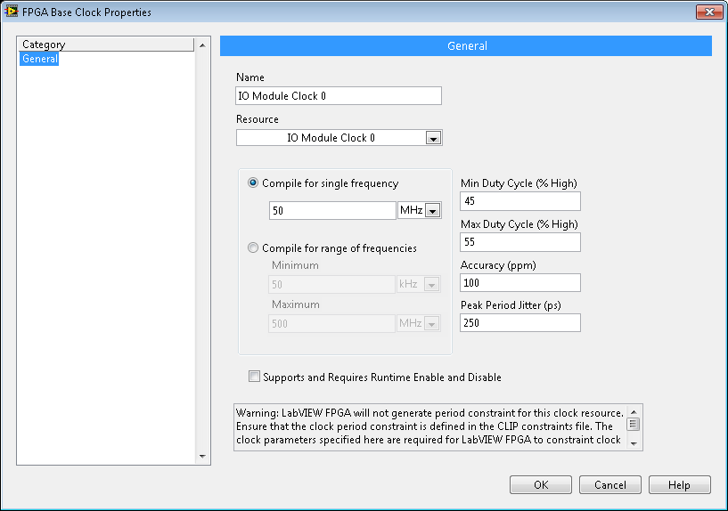
I add IO Module 0 as a base clock clock to the project:
And the dialog box above makes me think that IO Module clock 0 is compiled for 50 MHz, when I expect to be compiled at 250 MHz or 125 MHz.
Exactly how should I clock AI0 AI1 multi-sample IO nodes in the LabVIEW diagram?
Thank you
Steve K
Hi Steve,.
Looking at your path to the XML CLIP code, it seems that you are using the 1.0.0 version of the CLIP. This does not include the "Data Clock" signal and uses only IO Module clock 0/1. There were a few additions in the latest CLIP who could have incompatible with Labview 2013, so only one can use the 1.0 version. The CLIP of 1.0 is good to use; Simply use the clocks of Module e/s.
The clock frequency listed in the IO Module clock 0 properties does not affect the frequency of compilation; the frequency is set by the constraints of the CLIP. I think that this value is used sometimes when generating constraints for some paths, so I would still recommend the 125 MHz configuration.
Documentation is really confusing, especially in cases like yours helps newer Flexrio with older Labview.
Kyle
-
How to power supply of NOR-DAQmx PCI-6071e using Visual C++?
Hello, I am a first year student Bachelor do a team project for school and I am completely stuck. The laboratory on campus has allowed us to use their PCI of NOR-DAQmx-6071e card and the school provides free Visual Studio 2008. We try to grasp the card voltage levels in Visual C++, but we do not know what code to use. In addition, we cannot buy Measurement Studio Professional (or a standard, incidentally). Can someone explain please how to read voltage levels? Code example would be much appreciated.
There is a sequence of function calls required to create a task. This document goes through the steps needed to include in a job. When you install the DAQmx driver, the examples are also installed and can be found as described here. It will take a few changes to ANSI C examples to use in Visual C++ that are described here. Hope this helps!
-
If I can't fix this in three days, you better have a better excuse than a constant repetition over the qeustion even four different texts automated does not help if ppl at microsoft is so it can understand this release pray I don't first and hurt u publish
Hello
· What operating system is installed on your computer? It's Vista or Windows 7?
· You use Microsoft applications (Windows Media Player or native disc burning tool) or any third-party app (Eg: Nero) to burn the CD?
· What is you get the exact error message?
Please provide us with more information on the issue, you are facing help you the better.
However, see below article on how to burn a CD/DVD: http://windows.microsoft.com/en-US/windows-vista/Burn-a-CD-or-DVD
Diana
Microsoft Answers Support Engineer
Visit our Microsoft answers feedback Forum and let us know what you think.
If this post can help solve your problem, please click the 'Mark as answer' or 'Useful' at the top of this message. Marking a post as answer, or relatively useful, you help others find the answer more quickly.
-
Alternating - Signal Express sampling frequency
Hi, Im trying to get data using Signal Express + NOR USB-6211, I put the sample rate to 44100 Hz. and everything seems to be ok, but when I checked the data I realized this time column does not increase in a period time constant (ie. sample FREQ not fixed).
For example:
1 / (Time (1) - Time (2)) = 43478,26 Hz.
1 / (Time (2) - Time (3)) = 45454,54 Hz.
and it constantly alternates between the two frequencies. I have to perform an FFT and Im not sure what is the actual frequency and which continues.
I appreciate any help on this issue.
Kind regards.
This seems to be a bug that NEITHER should be aware of if they are not already.
If you set the frequency of sampling to 44100, the actual sampling frequency will be (20 MHz / 453) or ~44.150 kHz. The USB-6211 case has a basis of TIME 20 MHz (±50 ppm) and this clock is divided by an integer to derive the sample clock. The sampling frequency is always be forced to match to the top if you choose a rate that can only be achieved with a wide divider. Regardless of what the file shows, map DAQ itself samples at a uniform rate (unless you use an external clock, or something like that...).
As for the behavior in the column duration... I know exactly how you look at it but I get the same behavior is written my data using 'absolute time' for the time column to an ASCII file (or by using a file LVM, which always uses the absolute time). With the help of 'on time' however gives me a correct result. I can't speculate on the cause... it seems likely to me that there is a comma floating rounding error (absolute time is in terms of seconds since 1904, so the software works with a large number at the same time requiring great precision).
Best regards
-
I bought 6 s 2 weeks ago.
I found my 6s signal strength is less than 6 s of my friends, with the same telco provider.
We put our phone next door. And my 6s has shown more low-power signal compared to theirs.
Can I know how to check?
Or is my issue 6s quality?
I use case TPU of military. The seller case used force to push my 6s in the case initially.
The team would cause damage to the antenna and the cause of my weaker signal?
Please help and advise. Sincerely, I'm looking at your comments.
Another way to test is to make sure that the two devices are out of the case and test. It is very possible, the case that you use, and by your own admission, your phone was forced to, causes the degradation of the signal.
-
Satellite 1005: Push the power button, will turn off the AC power.
Laptop: Toshiba Satellite 1005
Problem: When I press the power button and let go, the laptop immediately loses all power.
I use the power cord plugged into the laptop, the power supply light is green, but when I press the power button and let go, as soon as the power light goes black(turns off), nothing happens.
Howerver, if I PRESS the power button without letting go, power LED lights, but the laptop won't boot at all, no Startup logo, no sound no matter what.
It's the second time this has happened, the first time, I let stand overnight and the next day she booted up fine.
Currently, the laptop is cold, it did not work, but always the same thing as described above.
There are no changes made to the laptop.
Any ideas?
It seems that the contact, the power button is faulty. Better to elevate the laptop to a Toshiba service station for a check.
I n ' t´t think that it is a software failure.
Good bye
-
Satellite 2450-201 does not start with battery power
Can someone help please, I can not turn on with the battery at all. When you plug the AC, the laptop powers up without problem. And after the intitial power on, I can get to the battery without any problem. But it won't let me power up via the battery at all.
Can someone advice, is there some settings that will help or do I need a new battery?Hello
What about the battery charge status?
The battery is fully charged?Try unplugging the power adapter and remove the battery from the laptop for a several times (15-30 min) and then reconnect the battery and try to turn on the laptop.
I also think that you should check if the problem also occurs with the new power supply. Eventually, there is something wrong with the battery, and you need a new.
Sorry for these general suggestions but you know, we can only speculate about the problems.
-
Workstation HP Z620 dual xeon: really only 1 6-pin power connector on the graphics card?
Hello
I have a question about the HP Z620 workstation.
recently bought a dual xeon with 960 GTX installed on the 6-pin connector.
as I can't find any other power to use nor on the power connector
or nowhere on the set, I wonder how a graphics card must be powered only
needs
1 x 8-pin
or
1 x 8-pin + 6 pins
or
2 x 8 pin?
I know there are some discussions about this in this forum, but I did not understand
the solution. Some said there are adapters to go 6-pin to 8 pin (or 6pin to 2x8pin)?
But how is that possible?
like many, I know, 75 watts are max of the pci-e connection, 75 other watts Max for 1x6pin.
so plug any adapter, 1x6pin for graphics cards that need much more power would be
According to the standard / danger, right?
and what about graphical installation double?
would be happy if someone around could help me with this.
best regards
Chris
The search box on this page by default search only this forum, and it is very convenient. If you type "extra", you will find a lot of info.
The Z620 has two of these 6-pin cable, and HP got creative and molded into two empty containers down to the black plastic fan holder before. So, one is being used by you and the second is sitting there plugged and similar, it is used, but it is stored just it did nothing... the fan is powered differently.
These extra HP 6 - pin PCIe power cables are not standard ATX... they are better. The ATX standard is 75 watts can go up to the card out of the slot, and another 75 watts can come via the additional 6-pin cable. HP 6-pin cable can do a bit more.
This is the message that you want to read, and there there details that were not in any of the HP manuals that I searched through, but the answer was on the label of Z620 power supply. 12V 18A each, plus adding info on some special HP adapters that allow you to take a HP 6-pin and divided to two 6-pin connectors or cable HP 6-pin connector 8 pins. Watch here.
-
Amnesty International and counter sync + USB signal stream (USB-6210 vs USB-6341)
Hi all
I'm at a stage of identification of a material suitable for the following tasks:
- 5 analog inputs (AIs) of reading at the same time, tensions at a rate of kSps (at least) 10,
- application captures 2 inputs using timers (detection of contours with timestamps), square wave entry with duty ratio of 50 percent and about 1.5 kHz frequency and variable pulse width / frequency (from 2 sensors hall, representative of the DC motor rotation speed and direction, quadrature signals), resolution of timestamps should be (at least) 50 ns,
- AIs and counters should behave in a deterministic way, and must be synchronized in a way,
- data to be transferred via the USB port of a host computer with Matlab Data Acquisition Toolbox (unfortunately not LabVIEW).
I've identified the long USB-6210 USB-6341 and potential candidates of material to accomplish the above tasks, but after reviewing several documentation and the topics of the forum, I'm still a bit confused, if both are fully working and my approach described below is not working properly.
Counters: I intend to use the internal time base available 20 MHz as being the source of meter to get into account the resolution of timestamp 50 ns. External impulses hall are used as sample clock (about 1.5 kHz, see above). As the pulse width varies, the sample clock is not constant.
AIs: Using a 10 kHz internal clock signal derived from the time base of 20 MHz for timing and analog inputs (trigger) start-up and counters simultaneously material should translate into the required synchronization and deterministic behavior.
It work? Other recommendations?
Next is the USB data transfer: all HAVE 5 and 2 data entry of the meter must be correctly transferred to the host computer (the corresponding rates are shown above). USB-6210 is capable of 4 USB signal flow, device USB X range (6341) offers 8 of them. Unfortunately, I could not understand the exact meaning of the expression "signal flow" still. Do I need 1 flow of input signals (would be 7 for my application described) or 1 stream for all analog inputs and 1 for counter inputs (lead 2 streams for my request). Is there no further details on this approach (more than Streaming of signals of NOR) USB signal flow?
Any challenge to the described application that I might have forgotten? 6210 USB seems to a very limited number of entry PFI, maybe even too low for my meter participate application?
Looking forward to your comments and advice.
Concerning
jAwA
1. I recommend the X-6341 series on the M-series 6210 sake of counters/timers. It is more of them, and each of them is more capable. It can also have a great FIFO embarked for meters that may be important in certain tasks, although I don't think that you currently deal with one of them.
2. your general concepts on timing & sync are satisfactory. You will be able to share and to route signals that help ensure synchronization and determinism between the timestamps for your various tasks. Note that for meter entry tasks, you need set up the trigger 'Arm Start' rather than the regular start trigger.
3 is not authoritarian, but I believe that the flow of signal # will correspond to the tasks #. For you, it would be 1 task of HAVE and tasks CI 1 or 2. (Not clear if you have 1 Encoder with 2-channel quad that would require 1 task of CI, or if you have 2 encoders with 4-way quad).
4. pay attention to the hall effect signals that are not virgins. Digital filtering is available and probably better on the X-series, the series M.
5. strictly speaking, edge detection is a type of digital input task that produces samples but no timestamps. Ideally, I would like to parallel wires on the two digital inputs for the entries of detection and counter change to position quadrature decoding. Then I would sample the counters Encoder 1 or 2 using the internal pulse 'event of detection of change '. I would create another counter timestamp change detects pulses as well.
-Kevin P
-
Support of NOR-DNET for LabVIEW 2013
We currently use OR DNET 1.6.6 with LabVIEW 2011. I installed LabVIEW 2013 now also on my computer and tried to synchronize all of the drivers with my installation of LabVIEW 2011.
Well, it seems that NEITHER-DNET does not support LabVIEW 2013, at least officially. compatibility of Version of LabVIEW and NOR-DNET indicates that NEITHER-DNET 1.6.6 supports 2011 NOR-DNET 1.6.7 2012 LabVIEW and LabVIEW.
The list NOR system driver November 2013 set OR DNET 1.6.7 defined pilot. When I try to install it, there is no support for LabVIEW 2013.
My question is, if there is a plan to include support OR DNET for LabVIEW 2013 or later in the game to pilot?
I copied the directories vi.lib\DeviceNet and vi.lib\nidnet of LabVIEW 2011-2013 and I can load my programs without any problems. I always did not build an executable and does not run on the test set-up, but projects can be loaded in LabVIEW 2013 without any screws of brocken. should I expect any problems running LabVIEW 2013 with the NOR-DNET to 1.6.6 and 1.6.7 driver?
Nick
There should not be problems but it is a former pilot, we will not be updated for the future version of labview.
Maybe you are looking for
-
What better way to use Win XP - Satellite L350-150 or Sat P300 - 18 M
Hey Yes,. I m planning on purchasing a L350-150 or a P300 - 18 m and I would like to install Win Xp on it.I have a Win XP CD I want to use for this purpose. These models have the problems to decommissioning in Win Xp. (e.g., hard disk, etc.) See you
-
synchronization of presentations keynote with a small team
Hello, I'm looking for an effective way on the sharing of a presenting keynote with a team of 8 people with iPads. Ideally, the presentation will be synchronized so that when it has updated all versions of team members will be updated to the latest v
-
After years of trouble free service, my 3055 HP will not print. (It will always copy). I get a '79' error that says it's a firmware issue. Electric bike does not help. I have tried downloading the firmware of HP thought a re - install might work, b
-
D3drm.dll is not loaded, this program requires a component missing windows
I'm trying to run a program of simulater of flight that I have used before and I get this message. If anyone can help me with this it would be greatly appreciated. I've looked everywhere but can't find. Thank you.
-
WUSB54GC Wireless - G USB Adapter question
I have a vista computer running with a wireless router model: WRT54G2 V1, and a computer with adapter WUSB54GC xp who usually find the wireless network, im using WPA-Personal encryption. Any help would be grateful. Oh and by the way, I can connect to