NI 9223 - input current range
Hello
The http://sine.ni.com/ds/app/doc/p/id/ds-260/lang/en datasheet speaks only of the voltage range to the analog input. I don't see anywhere else having the limit on the current information. I guess we have a range of current for the analog inputs. Could someone give the document for this?
Thank you
The input impedance is > 1E9 ohms. Of the law of Ohm and about 10 V input voltage range, you can calculate the current both input<10>
Lynn
Tags: NI Hardware
Similar Questions
-
error of current range PXI-4130
Hello
I'm trying to configure PXI - 4130 with labview.
Volts DC and range is set to 1, 5V - no error.
Current limit and the range is set to 200mA, 2mA, 20mA - get the following error.
The error indicates that I do not have the range of right - which is not true. Also, well: Current limit value: 100.0e - 3. It is in fact 2mA himself in the VI.
Tried with the VI in llb as node property OR DC power.
Confused! Help, please.
************************************************
Property node (arg 2) in PXI_4130_SMU.vi
Invalid value for the parameter or property.Conflicting properties: current range limit, current limit
Property: Current limit are
Requested value: 2.0E - 3
Possible values: 200.0e - 6, 2.0E - 3, 20.0e - 3, 200.0e - 3, 2.000000Property: Current limit
The corresponding value: 100.0e - 3
Minimum interval: 40.0E - 6
Maximum of the specified range: 2.0E - 3Name of the channel: 1
State code:-225152
****************************************
Thank you
Manu
Thanks Steve, I did not use abandon it and initiate screws before making the beach setting.
Manu
-
Hello
After reading everything that specifications and manuals, I decided to ask a general question.
In the data sheets, user guides I've read, in general, there are two warnings for DIO:
-Do not connect the outputs digital circuits which operates above the limits.
-Do not drive the line with tensions outside its operating range.
Generally speaking they tell me I need to know when dealing with output and voltage when dealing with entries. So I have this question, can I wire a power supply for digital inputs directly without exceeding its "beach of normal operation and without any protection circuit? In fact, my feelings, this is not possible. But why certain documents produced clearly mention that the impedance internal inputs while that of others is not clear those? How can I determine if I can connect a signal directly to an entry (for example USB-6525 indicates a current limiter circuit, but I don't see a clear explanation in the datasheet USB-6251)?
As long as the input voltages are within specified limits, no damage will be the DAQ hardware. Logic devices often have two lines of non overlapping input, one for low input and high input. If the input voltage lies between the beaches, the performance of the device can be unpredictable. Also, check your power supply to make sure that this doesn't not exceeding when turned on or off as that could exceed the DAQ limit.
Lynn
-
SCXI 1338 - input voltage range
Hi all
I use SCXI-1338 blocks in modules SCXI-1125. Currently channels measure currents in the 4milliamps range at 20 Ma.
I'll be able to measure signals VOLATGE by connecting to the SCXI-1338 module, and what is the range of acceptable voltage AC or DC? And also should I do everything
changes in the SCXI-1338 module block in order to measure the voltage signals? I want to measure 20V DC signal controlled by a PLC.
Thanking you.
Well, what it really comes down to the Ohm's law in the end. V/r = I, you'll 20V/250Ohms = ~ 80mA which is well above the limit of the 1125 and the 1338. I recommend you either go with the voltage attenuator 1327 or you could possibly do external cables to a voltage divider. If you place a resistance of 1kOhm serial then your V/R = I equation turns into 20V/1250 Ohms = ~ 16mA max. To find your tension, you must create a custom scale to account for this new resistance. However, given that most of the resistance will be a mistake, it would be better if you measured the resistance of the circuit using a multimeter or an equivalent for an estimate more precise of the real resistance.
In the end, the 1327 is going to be a cleaner solution, but you can also go the road of voltage divider if this does not work for you.
Lars
-
Lack of analog input/output range
Hello!
I LV 8.6 installed on my PC with XP OS and my card is 6024E. I noticed that the analog input/output palette is not appearing or missing. I tried searching but no luck. NOR-Daq traditional 7.4.4 currently installed.
Try reinstalling the device driver CD/DVD and make sure you have selected traditional DAQ.
Say you you installed NOR-DAQ 7.4.4. But if it was made before you install LabVIEW, LabVIEW and then see.
-
Read the current range of field
It is easy enough to read the default Beach plot Y for any trace of a stacked graph, but this property does not appear to follow the currently applied range (EX: zoom manually or entered manually in the axis during execution). What property stores the current scale settings can (Autoscale, min, max, etc.)?
Thank you
XL600
If you have stacked locations, you must write to the Active Scale Y read property information of the scale for this specific plot.
-
Configure the input voltage range
I use an NI USB-6221 with SignalExpress 3.0 card.
The Spec for the 6221 map specifies 4 analog input ranges of +/-10V, 5, 1, & 0.2.
My question, how is the range of input voltage on the map on one of the beaches specified?
The closest thing I can find in SignalExpress is step 'DAQmx aquire', looking at the tab "configuration" of "Configuring the stage." There is a group called 'settings', there are areas of maximum and minimum input Signal, but context-sensitive help indicates that it is expected for the channel after the scaling values.
I also looked into MAX, but I see no way for me to directly configure one of these ranges.
Can someone explain how this works?
Mike
You look at the right thing. When you specify the min and max, the DAQmx driver and then automatically selects the best range of this signal. For example, the Council supports + /. 1 + /-1, at ± 5 and ± varies from 10 volts and a jury of 12 bits. If you enter max/min to + /-2, the jury will be set to the +/-5 volt range. Your resolution is then 10 (oscillation of the total voltage) volts divided by 4096 (2 * 12).
If you were using LabVIEW, you can get the actual voltage selected range by using channel properties DAQmx AI. Rng.High and I. Rng.Low. If you specify a min and max that is less than the amplitude of the real signal is greater than the actual scale used, then you cut your input signal. DAQmx does not have an autoscale. Take a look at Page 4-2 in the Manual of the M series.
-
off message input signal range by turning on pc - monitor hp s2031
Hello
I have a HP S2031's monitor I got a few weeks ago. After I got a new video / graphics card in the computer (because the original card couldn't handle all around 1600 x 900 (60 Hz) great things.) However, I just noticed that when I turn on the monitor and the pc - first before windows starts it is a message indicating that the input signal is out of reach of the settings at 1600 x 900 at 60 Hz.
Now, I don't remember see this message when the original video card was in the pc ~ but I also don't always stay right there while windows starts so I can't say with certainty that the message did not exist with the original video card.
I go to the menu on the screen section and settings are set for 1600 x 900 at 60 hz and I also right click on the desktop and in the display so that settings can also be programmed correctly it and everything is set correctly.
This isn't a problem, unless I'm trying to access the bios. I tried to go into bios to see what kind of options are there for the video configuration and the only options we configuration video AGP Aperture Size (64 MB). Main (AGP) graphics card. AGP hardware detected - AGP card. Only problem was that at the time where I got this far in the bios that the monitor went to sleep on me. which makes it difficult to get out of the bios and boot the computer normally on the monitor going to sleep on me.
Anyone has an idea as to why I'm getting that message about the input signal and how do I fix as well as how do I stop the monitor going to sleep while I'm in the bios?
I am running Windows XP Professional with sp3 and all updates and the monitor is the HP S2031. The graphics card is a NVIDIA GeForce FX5200 and the monitor is connected to the pc with the monitor's DVI port since this card has only 2 ports dvi on it. I had an old card in the pc (which has the VGA port) but he could not show the 1600 x 900 with this card (and I'm not sure that the message was there with the old card, since most of the time that I'm not just sitting there waiting to start everything)
I didn't notice the message until today and nothing has changed - other than the new video card and who is in the pc for about 2 weeks now.
Any help would be much appreciate.
Hello
Sorry that it took so long to get back to you, but things have been very busy here (between the two to get hit with a foot of snow before Halloween and loss of power for a week still to go back to normal)
In any case, as for the video card - it is a card ASUS NVidia GeForce FX 5200 which has 2 DVI connectors which him. According to the information on the map
Expansion / connectivity Compatible Slots 1 x AGP connectivity Interfaces
1 x S-video input - 4 pin mini-DIN (with adapter), 1 x S-video output - 4pin mini DIN (with adapter), 1 x video composite input - RCA (with adapter), 1 x video output composite - RCA (with adapter), 2 x DVI - I - 29 pin combined DVI, VGA - HD D - Sub (HD-15) 15-pin (with adapter)
Anyway, I tried to plug the monitor into the other DVI port, and it now works fine. I guess that a port is bad or it is not intended for making that comes with this monitor.
Thanks for the help and suggestions. So they were very much appreciated.
-
Limit NI9215 analog input voltage range
Hello
I use a NI9215 (mounted in a cdaq 9174) to acquire a voltage signal. I want to keep the tension as an integer and then later convert it to a voltage in the script of Fortran. To do this I need to know the relationship between integers and tension. If I use an unsigned integer I 0 is-10 for example (numbers aren't important as long as I know what they are).
I tried to taste a voltage signal (see the attached vi), where I have limit vmin and vmax at the return of V-10 and + 10. When I have a voltage outside this range, waiting for the signal to saturate at-10 or + 10 V, but this does not happen. I generally get +/-10.4 V which figure is the maximum range. This range would have been ok if it was exactly +/-10.4 V but it varies from something on the order of 0.5% between the different channels I use.
Is it not possible to set vmin and vmax that I'm trying to do and if so, what is then the point of vmin and vmax?
Concerning
PAL Egil
Hi pal_egil-
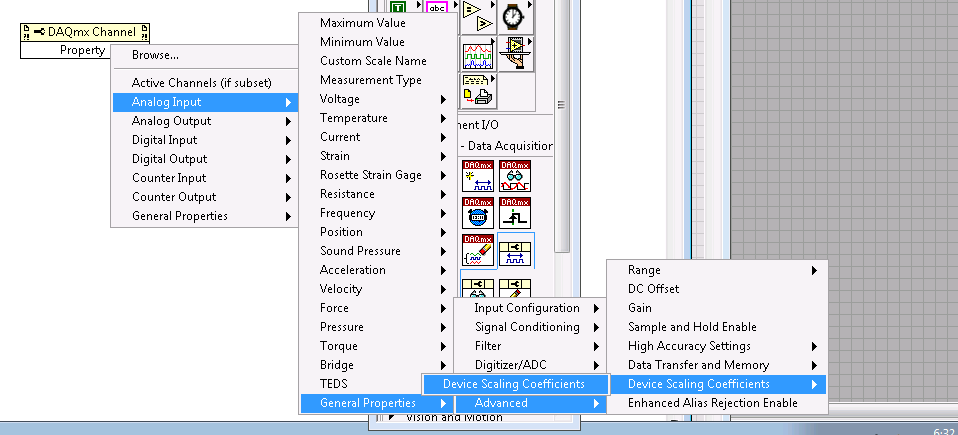
I guess you are trying to save time processor or (perhaps more likely) storage space by resizing the data yourself. I suggest that you use the version of DAQmx Read 'no'. This will give the most fundamental data type available and will save processing time (because it will not be scaling of tension and then re-scaling to an integer value simple on a linear scale of your application) and storage (because you will be able to store a single value of 2 bytes for each data point of your device).
So these unadjusted nationwide tension later readings, you'll also want to connect the device scaling coefficients for your module. These are accessible from the property of DAQmx channel node in LabVIEW, and a description of how to apply them to lectures unadjusted using LabVIEW for NOR-DAQmx.
I hope this helps.
-
Immediately make input current URL after open Safari or open new tab
Hello
When I open Google Chrome or open a new tab, I can type immediately the url. The cursor is active immediately in order to be able to type a URL and press ENTER to load.
In Safari, I have to click on the URL field first to make it active, and then I can enter the url. It's a not too expensive. I also want to be able to immediately enter my URL without clicking on the URL field.
Y at - it a setting or extension to make the work URL field immediately after the launch of Safari without having to first click on it?
Thank you very much for your help!
Safari should automatically put the fury in the url field without having to first click there and done in my case with Safari 9.0.3 and OS X 10.11.3 (but also did with all previous versions, I used). Possibly try to disable all extensions to see if that makes a difference.
-
Are there technical details for views on the current range of laptops?
In particular, the launch and the native resolution?
The form 'tech' are not exactly clear.
Hi LaurieShone,
Both computers display specifications are given below.
Specifications of display for 15R SE:

15Z display specifications:

Please answer for additional help.
-
Hello everyone,
In our report, we would like to the user input date range. Of course, start date and end date for the entries of users. First, we tested with a single number for the entry of the user before the date range.
COMMAND prompt type the calssID for
It works, but we message Report Builder in the next report.
ACCEPT classID NUMBER PROMPTED "Class ID:"
Select PRJ_REGISTRATIONS. CLASS_ID Prj_registrations
where PRj_REGISTRATIONS. CLASS_ID = & classID;
24333 ORA...
When we did research, lexical parameter, we founded examples of REF CURSOR with several features to use.
We tried to use our application, but they do not work for us.
If you have experience, please let us know.
Thanks in advance,
NY
Published by: New Yorker on May 7, 2010 10:43
Published by: New Yorker on May 7, 2010 10:53Try
and (TABLE.check_out_dt BETWEEN: Enter_Start AND: Enter_End)
S! GPS Mark Correct or help accordingly.
-
How to display the voltage and current of synchronously
Recently, doing a project on the acquizeing voltage and current synchronouly, then display. the design is welding a resistor(1%) 0.5 ohm in NI 6251 entered analog of her HAVE differential, then acquired the differential voltage at the input to convert current. At the same time, I hope to recover the path of analog input voltage. My problem is that the current profile data. Please help me .the program screenshot is show below. ---1. Perhaps you ask why not use no. - a way to get voltage at all port of AI, then in the use of the software less to get a voltage inputs HAVE. in this way, my problem is solved. I try, but the current accuracy is failure. because my current range expect is 1uA ~ 100mA. precision current samll won't be promised if you use simple ways for granted NOR 6251 voltage. NEITHER 6251 device spec (HAVE an absolute precision) (v) nominal range sensitivity absolute Accuracy (uV) 10 1920 112 5 1010 56 2 410 22.8 74 0.2 6.4 0.1 52 6.0 (I want to use this range to measure current samll) - cordially Shawnh.Chen
shawn1 wrote:
1. how show the waveform by accumulating 1 d data table, rather than showing all 100 acquisitionUse a waveform graph. Graphics keep history, you do not have to accumulate the data. He does it for you on the screen.
shawn1 wrote:
2. What is the minimum unit of identification of the TSC103IPT amplifier? I doubt that the 0.5uA can be identified? (0.5uV = 0.5 ohm * 1uA) Because I can't find anything on the auccary in TSC101IPT datasheet.The amplifier is analog. Thus, he can win anything. But you should really think about a higher resistance if you really want to measure this small of a current.
-
Tab 2 of the A10 input voltage?
I wonder if tab 2 a10 should work abroad where the electricity voltage is 220 instead of 110.
Any help would be appreciated. Thank you!
You will be fine, that the C - P35 AC adapter is bitensión with 100-240V input voltage range
Output 5.2V 2A.
-
What is input equivalent circuit of USB 6009 PFI0
The entry USB-6009 PFI0 is the same the analog input circuit stated in manual mode?
I use the PFI0 to trigger a measurement of voltage and it works a lot using a HP function generator.
When I try to drive the low entrance with my circuit looks like there's a pull up resistance to + 5 on the entry of PFI0 terminal.
This entry PFI0 will accept an output of comparitor from 0 to 15 volts with being damaged?Kip
Here is my solution to operate the PFI0 TTL digital input using a CMOS comparator.
I use a 2N4401 npn transistor.
Connect the transmitter to the ground terminal.
Connect the manifold to the PFI0 (there is a pull-up internal resistance to the 6009).
To connect to the Base of a voltage divider that limits in input current and decreases the CMOS voltage to TTL levels.
In my case I'm going to 0 to + 15 so my voltage divider is 4.7 k and 2.2 kohm to fall to 0-5 volts.
It is an Inverter circuit so your sense of trigger will go head on falling edge, or vice versa.
I hope this helps someone.
Kip


Maybe you are looking for
-
How to upgrade to iPhoto on an IMac (El Capitan, OS). Tried to find it on iTunes but I get a message, it is not available in the Canada.
-
Hello I have a laptop (Thinkpad 2082.BSG) T500, and recently, I had to repair after that the stettings of the factory have been resettled. However, for some reason it now takes a lot of time to stop (sometimes 10 minutes). I received advice that I pr
-
HP DV6t (B6C70AV) ENVY: which is 3.o usb port in my book!
Hey, can you tell me which is port 3.o. Until you say check SS or 3.o brand (I've already strained me eye seeks not), he did not, so you can tell me if my laptop is bluetooth compatible? If you could provide the link of specification for my product,
-
How to install a new windows 7 on a laptop with the dos operating system
I bought a new HP 15-s005tx with an operating system of back. Kindly help me to install a new copy of windows 7 using bootable dvd.Thank you
-
Hi all I want to display the version created date of my application. How to fix date identical file alx created date dynamically. Need help. Thanks in advance, SAL