Configure the input voltage range
I use an NI USB-6221 with SignalExpress 3.0 card.
The Spec for the 6221 map specifies 4 analog input ranges of +/-10V, 5, 1, & 0.2.
My question, how is the range of input voltage on the map on one of the beaches specified?
The closest thing I can find in SignalExpress is step 'DAQmx aquire', looking at the tab "configuration" of "Configuring the stage." There is a group called 'settings', there are areas of maximum and minimum input Signal, but context-sensitive help indicates that it is expected for the channel after the scaling values.
I also looked into MAX, but I see no way for me to directly configure one of these ranges.
Can someone explain how this works?
Mike
You look at the right thing. When you specify the min and max, the DAQmx driver and then automatically selects the best range of this signal. For example, the Council supports + /. 1 + /-1, at ± 5 and ± varies from 10 volts and a jury of 12 bits. If you enter max/min to + /-2, the jury will be set to the +/-5 volt range. Your resolution is then 10 (oscillation of the total voltage) volts divided by 4096 (2 * 12).
If you were using LabVIEW, you can get the actual voltage selected range by using channel properties DAQmx AI. Rng.High and I. Rng.Low. If you specify a min and max that is less than the amplitude of the real signal is greater than the actual scale used, then you cut your input signal. DAQmx does not have an autoscale. Take a look at Page 4-2 in the Manual of the M series.
Tags: NI Hardware
Similar Questions
-
How to configure the outputs voltage NI 9477
Hello
I'm trying to control a motor using a cRIO 9074 with the NI 9477 module. I would like to configure the output voltage of the module and if I understand correctly, they vary between 5 to 60 v.
How can I have a 24 v output?
Thank you.
JaneDoe94 wrote:
So if I understand correctly, I can use an exit as a switch?
If I choose resistance pull-up so the current stay under 1A, would this work?
For example, I am using R = 20 kOhm and DC = 24V. I need to stay below 5mA current.
9477 module is basically a relay to connect to the Earth. But beware of your voltage and current limits. The maximum current that can flow is 0.625 A by line. So make sure that you stay below that.
-
What is the input voltage max of the motherboard on Satellite 1110?
What is the maximum voltage for the motherboard in the Satellite 1110 please?
Because my current cpu (1.5 ghz celeron) is 1.025 volts and I would like to change the processor
something faster (cooling will be treated with btw XD)
The only problem being that the new processor needs 1.3 volts to run.Any info wud b appreciated
Is that not every processor is compatible with the motherboard.
1110 series computer are supported on the Intel Mobile Celeron processors up to 1.8 GHz.
Other processors are not compatible and the laptop won't work with faster processors. -
SCXI 1338 - input voltage range
Hi all
I use SCXI-1338 blocks in modules SCXI-1125. Currently channels measure currents in the 4milliamps range at 20 Ma.
I'll be able to measure signals VOLATGE by connecting to the SCXI-1338 module, and what is the range of acceptable voltage AC or DC? And also should I do everything
changes in the SCXI-1338 module block in order to measure the voltage signals? I want to measure 20V DC signal controlled by a PLC.
Thanking you.
Well, what it really comes down to the Ohm's law in the end. V/r = I, you'll 20V/250Ohms = ~ 80mA which is well above the limit of the 1125 and the 1338. I recommend you either go with the voltage attenuator 1327 or you could possibly do external cables to a voltage divider. If you place a resistance of 1kOhm serial then your V/R = I equation turns into 20V/1250 Ohms = ~ 16mA max. To find your tension, you must create a custom scale to account for this new resistance. However, given that most of the resistance will be a mistake, it would be better if you measured the resistance of the circuit using a multimeter or an equivalent for an estimate more precise of the real resistance.
In the end, the 1327 is going to be a cleaner solution, but you can also go the road of voltage divider if this does not work for you.
Lars
-
Limit NI9215 analog input voltage range
Hello
I use a NI9215 (mounted in a cdaq 9174) to acquire a voltage signal. I want to keep the tension as an integer and then later convert it to a voltage in the script of Fortran. To do this I need to know the relationship between integers and tension. If I use an unsigned integer I 0 is-10 for example (numbers aren't important as long as I know what they are).
I tried to taste a voltage signal (see the attached vi), where I have limit vmin and vmax at the return of V-10 and + 10. When I have a voltage outside this range, waiting for the signal to saturate at-10 or + 10 V, but this does not happen. I generally get +/-10.4 V which figure is the maximum range. This range would have been ok if it was exactly +/-10.4 V but it varies from something on the order of 0.5% between the different channels I use.
Is it not possible to set vmin and vmax that I'm trying to do and if so, what is then the point of vmin and vmax?
Concerning
PAL Egil
Hi pal_egil-
I guess you are trying to save time processor or (perhaps more likely) storage space by resizing the data yourself. I suggest that you use the version of DAQmx Read 'no'. This will give the most fundamental data type available and will save processing time (because it will not be scaling of tension and then re-scaling to an integer value simple on a linear scale of your application) and storage (because you will be able to store a single value of 2 bytes for each data point of your device).
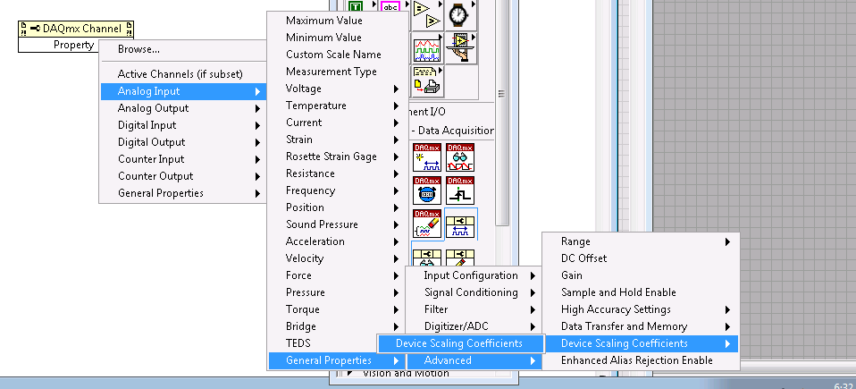
So these unadjusted nationwide tension later readings, you'll also want to connect the device scaling coefficients for your module. These are accessible from the property of DAQmx channel node in LabVIEW, and a description of how to apply them to lectures unadjusted using LabVIEW for NOR-DAQmx.
I hope this helps.
-
Custom control with couple or the input voltage system
Hello
I'm relatively new to LabVIEW and this is the first time that I'll use for an application of movement. I have a controller/chassis cRIO-9074 with a few modules NI 9514 IO, servo motors and drives, and I'm trying to do is to use a custom control in my system (a sliding mode control law) to generate the signal for the movement of the engines. I was able to produce a movement OR softmotion but so far I've been able to produce with position, speed and acceleration as inputs and to optimize PID gains. What I want to do is to send commands to torque or tension from the entrance of my right to command control is torque for motors. What I was wondering is if it's possible with the components that I use now and if someone could direct me to useful articles or books that can help me.
Sorry if is a noobie question but I only worked theoretically with systems of control far and I didn't simulate the results with matlab before that. It is the first time that I had to get the experimental results to validate my proposed control right. Thanks in advance.
Hi,.
This may be possible, but since sending the commands of torque or tension directly don't are not supported in scan mode, you can use your 9514 FPGA mode.
This link describes the components needed to run the FPGA device.
You should be able to find examples in the Finder for example NEITHER, but here is an overview of the use of FPGA that can be useful as well.
-
Tab 2 of the A10 input voltage?
I wonder if tab 2 a10 should work abroad where the electricity voltage is 220 instead of 110.
Any help would be appreciated. Thank you!
You will be fine, that the C - P35 AC adapter is bitensión with 100-240V input voltage range
Output 5.2V 2A.
-
Hello
The http://sine.ni.com/ds/app/doc/p/id/ds-260/lang/en datasheet speaks only of the voltage range to the analog input. I don't see anywhere else having the limit on the current information. I guess we have a range of current for the analog inputs. Could someone give the document for this?
Thank you
The input impedance is > 1E9 ohms. Of the law of Ohm and about 10 V input voltage range, you can calculate the current both input<10>
Lynn
-
I use a cRIO 9004. I noticed it has a chassis temp option. I was wondering if there was a way to find the input voltage. My unit is battery powered and I knew my batery voltage level. I'm doing some kind of a voltage drop detector.
I am a novice to Labview - I'm sorry if I missed something obvious.
Thank you.
You have not forgotten anything. Currently, there are no i/o chassis set up to read the voltage on your power supply. You'd have to do is to use an analog input module to read the voltage yourself.
Kind regards
-
Geographical address on the device voltage map PXI express
Members of the forum good day!
I am designing a PXI express card that must be inserted into a NI PXI express chassis. I read the documentation and specifications PXI, PXI express, of the cPCIexpress, but it seems that I'm not able to find any specification of voltage level for the BC (pins geographical address) that are present in the J4 connector. I need to know at least the input voltage prior to high level connect them to the FPGA that is on board. I'd like to connect a 12 Volt signal directly to a Bank of the FPGA 1.8V. Yes, I know, I can always use a (made with resistors) voltage divider in front of entrances FPGA, but better know the spcifications before conception to design something wrongly, in my view.
Can someone give a tip?
Thank you very much
Emanuele
A more precise answer to your question: the GA pins are floating or tied to GND. You are expected to pull up on your Board to what voltage is suitable for your device.
-Robert
-
How can I programmatically change the parameters of voltage range in a DAQ Assistant
Hello
First post here.
I need to be able to change the properties of voltage range of a daqmx assistant DAQ based on user input. My material, an SCXI module - 1102C does not change this property on a running task, so I would together the range of input voltage analog before activating the DAQ Assistant, or break the DAQ Assistant immediately after it starts, set the values, and then resume.
I don't know how to change the task ahead because the DAQ assistant creates the task when it is running, and there is no job before that.
In the attached photo, I have a conditional section, configured to run only if the loop iteration is 0. I take the task of the Daq assistant, sending him stop vi of task, set the property and then send the task with the snap the vi task. I can watch him run with lightweight debugging on, and everything seems to work properly, but on the second (and all others) iteration of the loop, I read I. Max and it seems that a re DAQ Assistant set it to the 5V. You can see what's going wrong here?
BTW, there is a continuous acquisition and the code doesn't produce error messages when executing.
I've encountered a similar question someone posted here in 2006, but his question was specifically a Labview API (VB, I think) and not a real solution of G.
Attached are the real vi in question and a PNG of the block diagram.
Thank you!
Ruby K
First of all, if you want to start getting beyond the basics with the DAQ hardware, you have to stop using the DAQ assistant and do it with lower level VI DAQmx. There are hundreds of examples in the finder of the example. You can even make a right-click on the DAQ assistant and select open front panel. This will create a Subvi, you can open and see what is happening behind the scenes. Do it. I think you will find that the task DAQ is recreated on each (although I'm not 100 percent the way parameters are established or maintained in each section of this sub - VI).
The second problem is that you have a bit of a race on iteration 0 condition. These two property DAQ nodes are running at the same time. Thus, when you read the AI. Max, this can happen before or after the AI. Max is located in the structure of your business.
Thirdly, make sure that involve you your son of the error.
-
Acquisition of data NOR-9205 Assistant set up range of input voltage
How to configure the module NI9205 to use the +/-200mV input range.
I use a custom scale, and it seems that I can not get an accurate reading. I use a shunt current of 100 Ma (max 10A). So I custom balance setting to have 100 x + b. The current flowing in the device is 2 amps and I get a reading of 12-13 amps after custom scale. Now I think the module is configured to sample for the entrance of 10V and I get an error of resolution.
Hi therbert
Since your custom scale is 100 x, to work on the beach of +/-200 mV to your NI 9205 module you must configure your input signal of maximum and minimum range for +/-20 respectively.
According to the equation: Range.max * scale.slope = 200mV * 100 = 20V
This will automatically configure to the scope of the module +/-200 mV to verify you can access the channel DAQmx property node and look for the analog input > General Properties > advanced > Range property, this will let you know in what range is the functioning of the device.
Concerning
-
With the help of MAX to configure digital input levels on a USB-6009
Hello
I use a USB-6009 box in a Windows environment. MAX allows me to configure the 8 bits in the port 0 as inputs or outputs. However, when I put the bits for all entries, their default level is high, and the "ALL LOW" button is grayed out. Is there a way I can turn this button to set the bits all low entry and therefore be configured to read a + 5V input pulse?
Concerning
Geoff Hammond
When you set up the pins as inputs, you can read 0 or 5 volts. It makes no sense to set then high or low. No PIN disconnected feel of course a logic 1 because of pull-ups on the device.
-
Configuration of input DAQmx terminal and choice of the sample mode
Hello
I'm studying 'Timing and synchronization features of NOR-DAQmx' from the following link,.
http://zone.NI.com/DevZone/CDA/tut/p/ID/4322
Pourrait
someone tell me how to Figure 2, input terminal in configuration
the part "DAQmx virtual channel creat? Shoud I double-click
the icon to change it? Or there is a way I can show in the
Block diagram as the sample in the DAQmx part mode?One
more question, in the DAQmx calendar part, how can I put continues «»
"" "Samples" here? It comes from the function palette? Thank you.No, you do not double click on the icon to change it. To answer these two questions, just right click on the device and select ' Create > constant "."
It comes to LabVIEW basics. I would recommend that you study only here before you start experimenting with DAQmx.
-
How to change the input range (DAQ assistant) with a digital command?
Hello everyone
I am currently working with the NI USB-6218 acquisition card.
In order to acquire a signal, I would like to be able to choose the input range of the DAQ with a digital command Wizard (and not opening the window of DAQ assistant) (as 'number of sample' and section 'rate'...)
Is this possible and if so, how?
Thank you very much in advance for your answers!
You can't with the DAQ Assistant so just click on and select "generate the Code of OR-DAQmx. You can edit the Subvi who performs the installation.
Maybe you are looking for
-
I can't look, just don't get 'no result '. For example, I want to get an email sent to a customer (current customer so I know that I have sent mail before), but no result...?
-
I lost my bookmarks toolbar and can't find a way to get it back
I accidentally closed my toolbar line tha's my favorites in there and I can't figure out how to get back. I've removed Mozilla and re-uploaded, but it came the same way.
-
Satellite M70: shutdown procedure sometimes does not work
Just have a problem with my newly bougt garage 70 M Satellite (1.7, 512, 40, combo, XP Home Edition). Especially when I stopped the laptop, it stucks and window gives the message 'PadTouch_FingerWnd program is not responding... ". "So now if I click
-
Pavilion g4: administrator Bios password
Hi all. Forgotten password. Model HP Pavilion g4-2304la Disabled system "70692182". help me pleaseee! : c
-
How can I get system recovery media?
Hi my hard drive just died taking me with him the secure partition containing vista. I have a sticker with the product key on the base of my laptop but I don't have a vista installation disk with my computer. y at - it somewhere that I can download s