Numerical simulation of e/s of FPGA on the development computer - strange results... Help, please
Hello
We ordered a 7851R DAQ card which we
have not yet received and we try to simulate using the
Setting "computer development". However, I can't seem to get the OID
to work properly. In fact simply opening "digital line input and.
Example of output.VI' does not have to wait for results. What happens in the
example of file is just, the indicators flash constantly and are not affected
by controls. Is this a known problem and I just need to wait for my
material or have I done something wrong?
Thank you!
Michael
You don't mention what version of LabVIEW you use, but if
you use a LabVIEW 8.6, there should be basically 3 options for
Debug / simulate your VI on the development computer.
The
first is to run the VI on the development computer using random
data for FPGA of e/s data. I suspect that this is the option you
currently using and only can be useful if a large number of logic in
your VI depends on the values of the e/s database.
The
second option is to use a custom VI which provides FPGA simulation
E/s data. That sounds as if it was what you are looking for. When you
Select this option, you will also get a button you can
Press to create a VI model that can be used to create your custom
VI. If you look at the diagram of the VI model, I think that it
should be relatively simple to understand how to insert your
custom code.
The third option is to run the VI on
the host but the use of I/O of the real world. In the latter case, a default value
bitfile is automatically downloaded to the FPGA for you and the data is
transferred from the device by the driver. Of course, you cannot use
This last mode until your material does indeed. I hope this helps.
Tags: NI Hardware
Similar Questions
-
Code error-61499 when you run an FPGA VI on favorable computer with e/s Siulated
Dear Forum
I have a problem running my FPGA VI on simulated with e/s Comupter development
I created a test bench, as described in
http://zone.NI.com/reference/en-XX/help/371599D-01/lvfpgaconcepts/test_bench_tutorial/
It works very well. I can read a write i/o nodes
But when I insert a control node of read/write (from the palette interface FPGA) in my host-VI to write a value directly to a control on my FPGA VI, I get the error-61499
The error occurs in the VI on my Hostcomputer ad message is:
An internal software error on the LabView FPGA Module has occurred. Please contact technical support.
The error doesn't happen, if I remove the read/write control, or if I do not speak.
The error does not happen, if I compile the fpga vi and let it run on my fpga hardware. It only happens in simulation mode.
The error mode simulated when I use the test bench to simulate the input signals, she also happnes, when I use random input signals.
It seems that the error does not occur when compiling. The slopes of simulated VI and the error occurs only when I call the read/write control.
Can someone help me?
I appreciate any suggestions
Thank you
David
OK, the problem is solved, thanks to the support of or who helped me:
The solution is, do not to have spaces and end of lines in the names of items frontpannel.
In simulation mode, a host vi has problems to access the elements of the frontpannel of the fpga vi with the read/write node if the façade elements have special characters.
-
I need a refund for an airport, I bought the infinite Flight Simulator and I didn't. I want a refund please. Help please.
Purchases are considered final, but you can try the page 'report a problem' to contact iTunes Support and see if they will refund or credit you: http://reportaproblem.apple.com
Or you can try to contact iTunes support via this page: http://www.apple.com/support/itunes/contact/ or https://www.apple.com/emea/support/itunes/contact.html
-
You try to run the scan mode and mode interface fpga at the same time is causing errors
I'm reading a 9236 9237 and a 9215 with the scanning engine and read from two 9211 modules with the fpga. It's because I need to acquire to 200 Hz with the 9236 9237 9215 but maximum rate of the scan engine is limited by the slower module in the system, which in this case is the max of 15 hz the 9211.
So to use both interfaces (scan engine and fpga), I followed the percisely given in this article for instructions.
1. the project has created and added the peripheral crio using the interface of the scan engine.
2. Add the target fpga and drag and drop the 9211 inside modules
3. has created the fpga in interface file with and compiled with no error.
4. interfaced with the file fpga at almost exactly the way the sample project of "getting started with 9211' by using the engine of analysis in the interface with the other modules.
5. after the errors to discover that I created a VI that tests for just the portion 9211 code (called "thermocouple FPGA method Test.vi")
The data returned by the interface fpga was nothing else than zeros on all channels, even if thermocouples were hooked on some of them. (all zeros as entries in the convert temperature vi gives-410, 6160 degrees F, if you happen to have the material to try this.)
I get the following error from the open fpga vi reference:
code error-61141
"Thermocouple method Test.vi FPGA.
Activities FPGA:Open FPGA interface reference.
Reserved outside LabVIEW FPGA: turns The RIO Scan Interface. You must set the mode Interface FPGA chassis in order to unlock the FPGA. »It's extremely frustrating, because as I explained, I've been very attentive not only follow the instructions for concurrent fpga and analysis but also to model my VI by the example of VI, even if only for the moment, just to try to work things out.
Any help would be appreciated as I need to fix this for the further development and I am somehow in a lack of time. I opened a support ticket (reference #7256226), but the app engineer had no time to answer.
My system:
cRIO-9014 controller RT with crio-9104 bottom of basket.
LabVIEW 2009
Latest drivers and peripheral software pc and rio (RIO scan 3.2 engine support june2009)
rex1030 wrote:
I'm reading a 9236 9237 and a 9215 with the scanning engine and read from two 9211 modules with the fpga. It's because I need to acquire to 200 Hz with the 9236 9237 9215 but maximum rate of the scan engine is limited by the slower module in the system, which in this case is the max of 15 hz the 9211.
This should not be the case. 9211 data will not update with each sweep, but you should be able to run the scan faster than 15 Hz without problem. Do you have specific issues with this?
So to use both interfaces (scan engine and fpga), I followed the percisely given in this article for instructions.
1. the project has created and added the peripheral crio using the interface of the scan engine.
2. Add the target fpga and drag and drop the 9211 inside modules
3. has created the fpga in interface file with and compiled with no error.
4. interfaced with the file fpga at almost exactly the way the sample project of "getting started with 9211' by using the engine of analysis in the interface with the other modules.
5. after the errors to discover that I created a VI that tests for just the portion 9211 code (called "thermocouple FPGA method Test.vi")
You can try making sure that the chassis is set to mode Interface FPGA and the setting is deployed. I wrote that article that you referenced says will select the deploy option later and not explicitly speak to deploy the chassis later. Run a VI with a reference open FPGA vi not automatically deploy chassis settings if you need to do it explicitly. Try the following steps.
1. right click on the frame element and select Properties. Make sure that the Interface FPGA option button is selected. \
2. right click on the frame element and select deploy.
3. repeat your VI.
The data returned by the interface fpga was nothing else than zeros on all channels, even if thermocouples were hooked on some of them. (all zeros as entries in the convert temperature vi gives-410, 6160 degrees F, if you happen to have the material to try this.)
I get the following error from the open fpga vi reference:
code error-61141
"Thermocouple method Test.vi FPGA.
Activities FPGA:Open FPGA interface reference.
Reserved for LabVIEW FPGA outside: The RIO Scan Interface is running. You must set the mode Interface FPGA chassis in order to unlock the FPGA. »The likely cause of this error is that the setting of the FPGA Interface on the chassis has not been deployed. If the chassis is still Mode Scan fixed personality bitfile will be loaded on startup and the FPGA will be locked.
It's extremely frustrating, because as I explained, I've been very attentive not only follow the instructions for concurrent fpga and analysis but also to model my VI by the example of VI, even if only for the moment, just to try to work things out.
I'm sorry that you have had difficulties. Assuming that I'm wrong about the source of your problem, it seems we have to update less than Ko to include the deployment step.
Any help would be appreciated as I need to fix this for the further development and I am somehow in a lack of time. I opened a support ticket (reference #7256226), but the app engineer had no time to answer.
My system:
cRIO-9014 controller RT with crio-9104 bottom of basket.
LabVIEW 2009
Latest drivers and peripheral software pc and rio (RIO scan 3.2 engine support june2009)
-
Multisim 12 - by clicking on the button "stop the simulation", does not seem to turn off the circuit
Greetings.
I recently installed 12 Multisim and have not changed the basic operational parameters, I know...
Shortly after installation, the application is an update.
Your help is apprecaited to understand what is happening...
Steps to recreate:
1. start multisim.
2. open a very basic circuit that includes a battery 10V with the ground, a lamp, a voltmeter between the lamp and an ammeter in series.
3. use 'switch' at the top right of the appliation multisim window to run the simulation.
4 lamp shows a 'enlightenment' and voltmeter indicates 10V and ammeter indicates .1a circuit.
5. use the switch to stop the simulation.
6. no change in the circuit or lighting of the lamp measures.
7. same results if the simulation starts the arrow and the red square are used to start and stop.
If I close it and reopen it circuit, the circuit begins in the OFF state, but will not OFF If when you select stop simulation.
This is the case with several circuits, those provided by the College and the other that I created based on the same design.
Multisim restarting has no effect to correct this observation.
It doesn't seem normal that when the simulation running, values or apparent lamp lighting does not change. The simulation doesn't have to go back to the start state (OFF) when I stop the simulation?
I captured the homerun status after stopping the simulation.
Thanks in advance for your help.
Zan
Hi zanzarista,
Multisim retains the values for everything in the circuit when the simulation is stopped. Which means that you are able to view the values on your instruments (such as multimeters) even after the termination of the simulation. When you start a simulation once again, starts all over again and that's why you see a 0 momentarily.
It is the way in which the software is intended to work.
I hope this works.
-
FPGA: Change the sinusoidal signal generator
The sine wave in the FPGA palette generator, that's what I need to do
but he can't exit do 'cosine', which is outside of 90 degrees. I need 120
degrees. To avoid discouraging, I opened the façade on the sine wave
Express VI generator that turned into a normal sup - vi. I changed the
a digital constant corresponding to 120 degrees out of phase, and the name was changed
of the output pin.The module will not compile. First mistake was a wire that was a type of variable, the
Fix suggested to check a box for pre-allocating did not work so I made the table
the length constant of 1024 (that is, it is supposed to be). Following error was
that one line of vhdl file was too long (32 k characters for a specification of length 4 k max
characters).Just for grins, I put the original VI Express return with the release of cosine and
It builds correctly.There was a big damper on the modification of the vi. However, I didn't know that
simple conversion to a subvi and the tweak of a constant value would break.Is it possible to get an updated the express vi for this application, or advice on how
changing the text that is there? The compilation breaks mainly online VHDL
length associated with the range of 1024 points.I can roll my own generator of sinus by using some examples, not a big problem but
It will cost you some time. Another option might be to run two generators of sinus
and specify a different phase, but I'm not convinced that over time they
will be exactly synchronized. Change the Express VI is a much better
option.Thanks in advance,
Bill
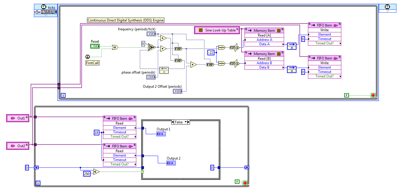
I discovered the hard way that LabVIEW 2011 has no records. After reviewing various options, I settled on the FIFO. The code presented here works well, but it is not save space on the FPGA to the wire using two generators of sinus with a phase difference in hard on one of them. For now, I'll use two sine generators, if this turns out to be unworkable in practice due to the relationship of phase adrift, then I'll look at it again.
The frequency and phase of the compensating controls are fixed point numbers formatted in zero whole bit and a 32-bit word. Bed down while the loop is synchronized with the loop timed by the FIFO, FIFO of 18 ticks timeout is two more than the 2.5 MHz in a loop which is a ditch-16. The IF block in the lower part, while the loop cut update control up to 10 KHz, 60 Hz sines more quickly.
Great experience, thank you for the help.
Kind regards
Bill
-
I just dug my copy of train simulator, and it does not work on Windows 7 64-bit. Ideas please
I just dug my copy of train simulator, and it does not work on Windows 7 64-bit. Ideas please
Thank you very much for all your suggestions. "Iwent with."
This can help with some (but not all the) programs/drivers:
(1) uninstall the program, if it is already installed. Then when install you / reinstall instead of double click on the Setup file, right click and select 'resolve compatibility issues.
(2) then click on 'Try recommended settings' and in the next window, click on "Start the Program" to install it.
(3) after he set up see if it works properly. Note: some programs may not be able to run in Windows 7.
and it worked.
did anyone tried the version updated? I read some rather disappointing reveiws.
Once again my kind thanks for all your suggestions
-
I have Windows xp and Vista on the same computer, my fligth Simulator is on xp. How do I play for vista or I need to install Island all on vista
Hi, CPC,.
Welcome to the Microsoft Answers Community!
You must install Flight simulator on vista as well as Windows Xp and vista are two different operating systems.
You log in to vista, you may not use any of the XP application and vice versa.
Thank you, and in what concerns:
Azeez Nadeem
Visit our http://social.answers.microsoft.com/Forums/en-US/answersfeedback/threads/ Microsoft answers feedback Forum and let us know what you -
Microsoft Train Simulator error Setup error "Unable to verify the media" keeps coming back.
Original title: Microsoft Train Simulator Setup error
Try to install Microsoft Train Simulator on vista and when installing on the error 'Failed to check media' 2nd drive keeps coming back. Have also tried on another computer that has XP and the same results. Can anyone help?
Hi Rick,
Given that the CD does not work in Windows XP computer also, there seems to be a problem with the drive itself.
Clean the CD or the DVD. To do this, use a disc cleaning kit. Or gently wipe the silver part of the disc with a soft and Lint cotton cloth.
You can read the following article and check.
If you are always faced with the question, so you may need to replace the drive.
-
Http method Post is not working in the Simulator (SDK 7.0) and not in the device with BB 5.0
I am a novice in the development of BB.
I tried to implement a simple Http Post request, but when running it in the Simulator (SDK 7.0), he gave an IOException.
I've first implemented the Http Get request and was getting the same error but that was resolved by adding "; deviceSide = true'on demand.
But while making the Post request parameters(username and password) were supposed to be written to outputstream open after successfully HttpConnection. I get the answer I used to get when I send two parameters as null.
But the app even when built against JRE 5.0 crashes.
Hi simon, peter
I made changes to my connection as as well as u say it, but still no idea if I am wrong, if I do one.
Now without using any suffix his run on my device but same answer as it was a GET request.
A modified version of class ServerConnection (in post above)
package com.httppostdemo.classes; import java.io.ByteArrayOutputStream; import java.io.InputStream; import java.io.OutputStream; import javax.microedition.io.HttpConnection; import net.rim.device.api.io.transport.ConnectionDescriptor; import net.rim.device.api.io.transport.ConnectionFactory; import net.rim.device.api.ui.UiApplication; import net.rim.device.api.ui.component.Dialog; public class HttpPostConnection extends Thread { private String mUrl = null; private byte[] mParams = null; public HttpPostConnection(String iUrl, byte[] iParams) { mUrl = iUrl; mParams = iParams; } public void run() { super.run(); ConnectionFactory connectionFactory = new ConnectionFactory(); ConnectionDescriptor connDescriptor = (ConnectionDescriptor) connectionFactory .getConnection(mUrl); HttpConnection connection; OutputStream outStream; InputStream responseData; final ByteArrayOutputStream baos; int responseCode; int bytesRead; if (connDescriptor != null) { try { connection = (HttpConnection) connDescriptor.getConnection(); connection.setRequestMethod(HttpConnection.POST); connection.setRequestProperty("Content-Type", "application/xwww-form-urlencoded"); connection.setRequestProperty("Content-Length", String.valueOf(mParams.length)); outStream = connection.openOutputStream(); outStream.write(mParams); outStream.close(); responseCode = connection.getResponseCode(); if (responseCode != HttpConnection.HTTP_OK) { connection.close(); return; } baos = new ByteArrayOutputStream(); responseData = connection.openInputStream(); byte[] buffer = new byte[10000]; bytesRead = responseData.read(buffer); while (bytesRead > 0) { baos.write(buffer, 0, bytesRead); bytesRead = responseData.read(buffer); } UiApplication.getUiApplication().invokeLater(new Runnable() { public void run() { Dialog.alert(new String(baos.toByteArray())); } }); baos.close(); connection.close(); } catch (final Exception e) { UiApplication.getUiApplication().invokeLater(new Runnable() { public void run() { Dialog.alert("Exception :: " + e.getMessage()); } }); } } } } -
Hello
I use card FPGA 7966R with Module of e/s 6587. I have two sets of screws FPGA, one that uses 6587 mode series (Serdi channel) and the other in parallel mode (Serdi connector). I'm trying to select one of the FPGA VIs via the host VI and I don't know if it's possible.
Some things to note:
- All IOs have the same names, FIFO has the same data type and name.
- Because they use the IO 6587 controller in a different configuration, I can't parallelize them and combine them into a single VI.
Thank you
MILIN
You should take a look at the function of Bitfile dynamic reference opened .
-
With the help of NOR-5641R with FPGA and the instrument driver
Hi Ran,
I don't think what you describe is possible for two reasons.
- You cannot run the pilot bitfile instrument at the same time as a user defined FPGA bit file
- AO ports are AC coupled, so you will not be able to generate a DC bias on them.
-
Photon counting using the FPGA of the series R. problem generation TTL signals
Greetings,
I try to use the R series FPGA to read and count the pulses TTL of a discriminator (count of photons of the Hamamatsu C9744 unit) connected to a PMT (Hamamatsu-H7422P-40). The release of PMT looks fine (signal.png H7422P-40) but the discriminator wasn't able to generate corresponding TTL 5V pulse. There was some scattered and random spikes, but nothing significant. Instead, the only stable the PMT signal is a single + 5V pulse no matter how, I adjusted the PMT (C9744 output.png) control voltage. The PMT and the discriminator is connected by an ordinary BNC cable 50 ohms.
I am really confused because it was supposed to be a really simple installation. Anyone have a similar question or have similar Instrumentation (but no problem) configuration? Comments/suggestions are greatly appreciated.
Thank you very much in advance!
Hi Kelli,
Thanks for your help. Sorry it took so long to get back to you.
I actually found the question. The discrimination of the Hamamatsu unit level is set too high that all signals got filtered. After adjustment of the threshold of manuallyt, I was able to get the camera TTL pulses. And 7842R worked correctly for count impulses. Everything works fine now. Thanks again for the input.
-
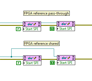
Definition of registry FPGA: using the reference transmission
Question of Labview FPGA basis. When I use FPGA read/write control to set a record in an FPGA, is there a difference between using a FPGA reference 'place' (connection FPGA VI reference Out on a block from the FPGA VI in the next reference) or directly to sharing the same node of reference? Image below illustrates the two spare connectors: they are functionally identical? If so, why is there an outside reference? Is it just to keep the more neat wiring diagram?
Yes, these two are the same, they would be for any reference type in LabVIEW. The top version is much more clean, however, isn't? Also, if for some reason you do not want to use error wire, wire reference here provides another way to enforce the order of execution.
Also note that you can drag down the node to read/write to read and write several items in a single node, and they can be a mix of reading and writing.
-
Resources on Rio fpga using the NI 9403 module
I use a CRIO and it works very well with my A/D and D.-a. When I add an e/s digital NI 9403 module, it eats all my resources even if I don't use all that in the circuit! Is there a way where I can use say only 2 or 3 pins e/s and not other use without him swallow all my resources.
I found the problem. When I added the module e/s I used the mode of discovery and he went. It seems it went past Scan mode for some reason any. When I moved the unit on Solution Explorer up next to two other files, I had made A/D D - A mode FPGA, he changed his mode of FPGA itself and then I could remove I/O pins as required. The icon, then changed when I pulled a PIN on my FPGA block diagram and everything was ok.
Maybe you are looking for
-
Automatic logoff on sleep? How?
I wonder if someone could help me please? I need a way to verify that my browser (in this case Chrome) is closed when I put my Mac to sleep, or he sleeps auto. Unfortunately, as you know, the default behavior is that applications remain open on slee
-
I can't download a purchased song
I deleted an album and you want to redownloa it, but when I go to the iTunes purchases that none of the songs on this album are here. I looked for the album on iTunes and I clicked on the album and it says purchased but I can't download it yet
-
Satellite L675 - overheating heavy tasks
Hello I have problem of permanent overheating with my laptop when running heavy tasks on my laptop (even while playing 1080 p h264 file is such task). So, with average CPU temperature of approximately 50% of charge going to ~ 80-90 degrees celsius an
-
Device = what it means & how can I get rid of this + thank you
[mailto:*** address email is removed from the privacy *] Envoy: Thursday, September 27, 2012 06:33 To: Nick Fleury Topic: Help Your server suddenly put an end to the connection. The possible causes for this include server problems, network problems,
-
No sounds in Outlook Express, when e-mail is received. I had chimes in COURIER & NEW MESSAGE NEW