Resources on Rio fpga using the NI 9403 module
I use a CRIO and it works very well with my A/D and D.-a. When I add an e/s digital NI 9403 module, it eats all my resources even if I don't use all that in the circuit! Is there a way where I can use say only 2 or 3 pins e/s and not other use without him swallow all my resources.
I found the problem. When I added the module e/s I used the mode of discovery and he went. It seems it went past Scan mode for some reason any. When I moved the unit on Solution Explorer up next to two other files, I had made A/D D - A mode FPGA, he changed his mode of FPGA itself and then I could remove I/O pins as required. The icon, then changed when I pulled a PIN on my FPGA block diagram and everything was ok.
Tags: NI Software
Similar Questions
-
Using the NI 9403 module as a source of tension for its own entries
I need to have certain diagnoses in a circuit that I build. I plan on the use of certain relays to throw a switch when certain events occur. This switch would be connected to a digital input NI 9403, as a way to detect the event.
To do this, I need power the switch itself, so he spends a tension that the NI 9403 module consider a digital camera 'high '.
Can I buy a power supply of 5V, but is expensive compared to what it should only do. I was wondering if it's permitted use / safe / sane... at one of the NI 9403 pins as a digital output and use it as a source of tension for switches? According to technical data sheets, I should be fine for power supply. I'm not sure if it's a decent way to do this.
My finished project requiring a current amplifier Board, I had to weld. So I decided that I might as well just add a voltage regulator to this Council and some resistance to simplify power. I never tried to use the NI 9403 module as a source of tension.
-
DAQmx 201105 error using the cDAQ 9403 module
I'm using the DAQmx C library of Borland Delphi programming. My hardware configuration is a cDAQ-9174/9178 with a 9222, 9401 and 9403 module. Here's where I manage problems at the moment:
I want to run three different tasks on my 9403 module:
Task1 is an output buffered with frame sample clock/cDAQ1/do/SampleClockTimebase to 100 kHz (channel 0-5)
Task2 is a software-timed output (20-25 channels)
Task3 is a timed software entry (channels 26-31)
Task2 and Task3 me give 201105 errors when I try to use DAQmxWriteDigitalLines and DAQmxReadDigitalLines, respectively. Create channels for these tasks works very well, however. Apparently, there is some reason to believe that the 9403 won't perform Task1, except that it works without raising errors. This work by accident and only because I am using channels 0-5? That's why I'm getting errors when trying to use the tasks 2 and 3?
Any thoughts are appreciated.
Hi André,.
This is expected behavior and is documented in the digital i/o considerations for devices of the series C using DAQmx.
The 9403 is registered has a series module that has the following restrictions:
- You may not use modules series and parallel together on the same task timed material.
- You may not use modules series for the trigger.
- You can do static and timed tasks at the same time on a single serial module.
- You cannot material timing in one direction at a time on a module in the two-way series.
You can do task 1, or you can do tasks 2 and 3. You can not do the tasks 1, 2 and 3 together, as you saw. You can do it with an additional 9403 if you move the software tasks timed to the other module.
The 9401 is a parallel module that does not have these restrictions. Snacking is configurable, however, which means that you must set the direction in groups of 4, but it seems that you are using too many lines for a single 9401.
-
error 50103 that the specified resource is reserved - name of the Task - 4 modules
Hi all.
I'm sorry I put this post by mistake in Measurement Studio for.NET: smileyindifferent:
Let me tell you my configuration:
software: Windows XP sp3, Labview 8.5 fr.
material: chassis OR cDAQ-9172 with 4 modules installed (in this order):
1 NOR-9217 (4 RTDs)
2 NOR-9217 (4 RTDs)
3 NOR-9219 (4 RTDs)
4 NOR-9219 (4 RTDs)
So, I want to acquire 16 temperatures.
In MAX v4.3, all works well.
As you have aspected, I got the famous 50103 error: "the specified resource is reserved. The operation could not be performed
such as specified'. «Task name: unnamedTask<9>'.»» -highlighting of module #2.My goal is to read these temperatures consecutively, I mean: mod1 ch0... Ch3, mod2 ch0... Ch3 and so on.
My program (vi) is like this:In a while loop I have a stacked sequence Structure that has 4 frames, each for every DAQ Assistant asigned and configured
for these modules.
So I have: Assitant1 for mod1, mod2 Assistant2, and so on.
Assistants work well in configuration overview mod (I see 4 temperatures on each module).
But in my program, I got the error above, on module2.I read something about this error and I understand that I can not use 2 or more resources at the same time.
I understand that a resource represents a channel on a module.
At each end of the DAQ Assistant, I have a Signal from Split (split in 4)
But with this setup and this algorithm, I guess I read all 16 channels in total consecutively, not at the same time.
Am I wrong?
How can I solve the problem? : smileysad:
Thank you.Somehow, I managed to fix it.
I did not use the wizard, I used the DAQmx Code, but it is very slow... I read all 16 times in 20 seconds, (I read each channel separately) but not everything installed, I thing this is why it takes so long.
Y at - it tips to acquire very quickly?
(I mean all 16 time to 1 second)
-
Using the SCXI-1520 module for measurement of torque
Hello
I'm working on a project that requires a measument couple in real time on a speed-shaft drivetrain configuration phase.
I have the SCXI-1520 module, and I think with a with a configuration of full-bridge strain gauge to do this.
The problem is that it is not possible to connect to a real-time measurement, so my first solution was using some sort of wireless transmission to receive data in the SCXI-1520 module
The Arduino + Xbee seems to be the best way to go, but at the same time, I think I might have a few problems of conditioning of the signal while transmitting data to LabVIEW through the SCXI-1520.
Don't you think it's the best way to do it, or is there a better solution?
Thank you!
Hi Kenny,
What type of operating system are you using? When you say 'Real time', do you mean look at a signal when it occurs? If you use communication networks, you will not be able to get truly control in real-time because communication networks is not deterministic, and you cannot guarantee the synchronization.
If you try to get a signal and he discovers that you buy it, you should be able to use the Arduino and LIFA with LabVIEW. Adding the SCXI-1520 will not add any additional resolution in this circumstance.
Best regards
Anna L
-
Use the same code module to multiple steps in the sequence
Hi all
I tried to implement a sequence that uses the same code for all steps module in the order, but I'm not returning to it when I need to send it commands. I got regarding the appellant the VI in a new thread so that it can be executed asynchronously. I can run the simple sequence and it will indeed open the VI and move to the next step. When I close the VI manually from the front, the TestStand sequence is completed, as planned. So it turns out that I have a lot more work.
My question is how to call the thread separate from the main sequence and other sequences overtime when I need to change the settings. If I insert a step in the Action, I have to select a file of VI, but from what I can tell, it opens another instance of the file and does not provide an interface with the other asycronously running instance. My next guess was to use a stage of education, but I was not able to understand how to configure the search string to call the VI settings. In addition, I don't know how to proceed. Please notify.
My intention is to start the module code (asynchronously) VI, run several different subsequences in the main sequence, which call this same VI and edit its settings, close everything and report the results. If I'm understand how TestStand is supposed to work, please let me know.
Thank you
GSinMN
What I do is use a queue to send data to the asynchronous VI. So he can run and whatever, but also receive orders from the queue. I use a motor of Action that contains the reference to queue and sends the commands. If you really just call the engine of the Action of your sequences.
-
Problem with the lines using the printer power module
Printing from your computer or copy it using the bed of glass is very well, but when we use the document feeder, we get dark vertical lines. I cleaned the glass and the rollers I could have access, but it is not improved. Any suggestions? Thank you.
Glad to hear that you're back on

 .
. -
Definition of registry FPGA: using the reference transmission
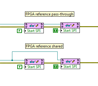
Question of Labview FPGA basis. When I use FPGA read/write control to set a record in an FPGA, is there a difference between using a FPGA reference 'place' (connection FPGA VI reference Out on a block from the FPGA VI in the next reference) or directly to sharing the same node of reference? Image below illustrates the two spare connectors: they are functionally identical? If so, why is there an outside reference? Is it just to keep the more neat wiring diagram?
Yes, these two are the same, they would be for any reference type in LabVIEW. The top version is much more clean, however, isn't? Also, if for some reason you do not want to use error wire, wire reference here provides another way to enforce the order of execution.
Also note that you can drag down the node to read/write to read and write several items in a single node, and they can be a mix of reading and writing.
-
How to add new resource to existing routes using the API / Interface Tables?
Hi friends,
I need to add new resources to our existing ranges. The number of records is more than 10,000. So I need to create an anonymous block for her. But I don't know what are the tables Interface / API to use for their insertion. If anyone can guide me how can this be achieved, I would really appreciate it. If you can provide me with an example of code for it, it would be the best.
Thanks in advance.
KMHi KM.
PL insert the line in the BOM_OP_RESOURCES_INTERFACE table with
INSERT INTO BOM_OP_RESOURCES_INTERFACE
(process_flag, transaction_type, organization_id, routing_sequence_id, operation_seq_num, resource_seq_num,
resource_code, assigned_units, usage_rate_or_amount, basis_type, schedule_flag, creation_date, effectivity_date)
VALUES
(1, 'CREATE', organization_id, v_rout_seq_id, v_operation_seq_num, v_resource_seq_num, v_resource_code,
v_assigned_units, v_usage_rate_or_amount, DECODE (v_basis_type, 'BATCH', 2, 'ITEM', 1),
Decode(i.schedule_yes_no, 'YES', 1, 'NO', 2), sysdate, v_eff_dt);Where, v_eff_dt = SELECT operation_sequence_id, effectivity_date IN v_oper_seq_id, v_eff_dt
OF bom_operation_sequences b
WHERE b.routing_sequence_id = v_rout_seq_id
AND b.operation_seq_num = v_operation_seq_num;Then run simultaneous 'Bill and routing Interface' to import resources into the existing ranges.
HTH
Sanjay -
entry of mV/psi for SCXI-1102 using the SCXI-1308 module?
Is there a way to physically connect a mV/psi signal to an SCXI-1102 module, which also uses a block to connect SCXI-1308? What I've read, the terminal block can use only a signal 4-20 or 0-20 Ma, right? I don't see the pins that the terminal block plug to use for output of the pressure sensor mV.
Thank you very much for the help!
TQ
Hi FMC_Pumptest,
The 1308 Terminal is designed for the current input. You are right that you have entered for 0-20 mA and 4-20 signals my with this block.
Kind regards
-
Using the CRio NI9265 module as current source
My apologies for what is pretty basic - I come to this Chem Eng background rather than electric. I have a CRio-9012 controller with a 9265 module 0-20 my (among others). The power supply to the CRio is 24VDC. I want to use one of the outputs as input to a power controller Watlow DIN-a-mite, which will lead in turn 10 a / 2.5KW heating.
The datasheet for the power controller indicates that the input command is powered by current loop linear, 4-20 my DC, requiring an available with 6.5 VDC power source. Am I right in saying that I should compare 6.5 VDC voltage compliance for this module (12 DC max), so this arrangement work?
Kind regards
Chris.
Hello ChrisTighe,
That's right, that the installation will work.
The 9265 will display up to 12 VDC, and your device requires a maximum of 6,5 VDC.
-
Tecra S3 - cannot use the new RAM modules in the B slot
Hi all
I just bought two RAM modules of 1 GB to replace my old 512 MB one. This, as far as I know, is the maximum allowed by my Toshiba Tecra S3 (PTS30E-01000QSP).
When I put a module in A slot, the machine works perfectly; If I place a second in location B, the computer tries to start but, at a time given, it freezes just (no activity of the HARD drive or changes on the screen) and the fun begins racing on as if some process crashes in the CPU to heat that make it up. At this point, I was always afraid that the heat can damage the computer and be turned off by pressing the on/off switch, so I can't tell if the problem is solved simply waiting.
I swapped the two modules on A slot and the two work well when they are the only one on the machine. Pretty funny if I place (as is the case now) has the old 512 MB in the location B as well as a single module of 1 GB in slot, it works!
My BIOS has been upgraded to the last, that I could find in these same pages (version 3.20 if I'm not mistaken), but it made no difference. If I enter the page of the BIOS when the two 1 GB modules are present, the BIOS recognizes that they are there. This behavior occurs when I try to start Windows or Linux.
Honestly, I'm puzzled. Someone has an idea what can happen and how I could place the two modules on my machine?Thank you very much and sorry for the long post
O.
Hello
The modules you purchased exactly for your Tecra S3? Maybe that they are not compatible with the laptop and it hangs after a few minutes.
Normally, the Tecra S3 can handle up to 2 GB and that means 1 GB in each slot. For modules of Toshiba part number is PA3411U-1M1G.
In my opinion you should try it with other modules with original 512 MB module everything works so I guess your new RAM is the cause of this problem.
-
OK with photography package creative cloud why did it let me use the lightroom develop module?
I tried to find an answer to this, and he told me to buy a subscription. I bought the package of photography creative cloud for 9.99. It is supposed to be included I thought.
Download you and install the program?
To start https://helpx.adobe.com/creative-cloud.html the Cloud
-Installation, update or uninstall and launching after installation
Or, https://helpx.adobe.com/manage-account-membership/cc-reverts-to-trial.html
-
How to use the target FPGA and co. on the same chassis cRIO?
I have a cRIO system consisting of a master chassis 9074 with several modules IO and EtherCAT 9144 slave unit.
I want to run a CIE (see: http://zone.ni.com/devzone/cda/epd/p/id/5333) on the chassis of the master, this uses the analytical engine. At the same time I have to do some very urgent measures if I want to use the Board in hybrid mode, using analysis and FPGA engine at the same time (as described here: http://digital.ni.com/public.nsf/allkb/0DB7FEF37C26AF85862575C400531690.)
But as soon as I add the FPGA target at one of the chassis, the feature of the ice on this chassis stops working. After some research, I found that the CIE can initialize is no longer the modules belonging to the frame that has the target FPGA on it. Error in the method Init of the CIE is: 65700 (indeterminate). This occurs when you try to use "for a more specific class' on the modules configured with a target FPGA on it.
Someone knows what can cause exactly this problem and perhaps provide a solution/work around?
Many thanks in advance.
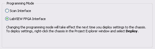
Hybrid mode requires you to have a bitfile compiled running on the FPGA to be able to read the Scan Interface IO Variables. Move the target FPGA at the RT target module will allow Interface of scanning for this module, but the frame will always mode Interface of LabVIEW FPGA.
To get fair access to the scan mode for the frame, right click on the chassis in the project, and choose Properties. Then, modify the Scan Interface programming. If you want to continue using the programming of FPGA and the Scan Interface set (hybrid mode), you will need to compile a bitfile (empty if you do not want programs on the FPGA again or containing your FPGA code). By compiling, the support of the module scan mode for the modules under your RT chassis is compiled in your custom bitfile. Then, on your VI RT, you need to use reference FPGA VI open to your newly compiled VI. Once this VI is deployed and ongoing implementation, you get the data from you are the CIE.
For more information, see this knowledge base article and Reference Interface of Scan CompactRIO and procedures.
-
Integration of Code FPGA on the rest of the project.
Hello, thank you for helping me.
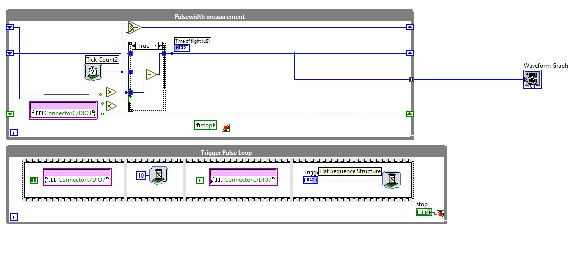
I recently started on the MyRIO, NOR I have the following code to handle a ultrasonic rangefinder:
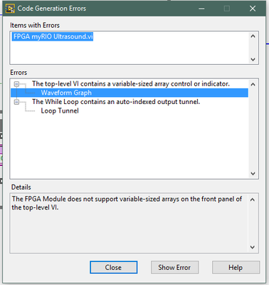
However, when I try to compile I get the message:
Apparently many of the most common features of Labview can not be used on a FPGA target. However, the code for the Rangefinder is a small part of a larger project in which I have to use such functions, so my main concern is the weather, I'll be able to integrate this code with 'normal' labview FPGA code on the myRIO, if possible, how?
I would create as for example a 'top' VI which has its own code (showing the waveform graph after the realization of certain mathematical operations on the will appear given by the VI as well as some other stuff).
Thanks again for helping me.
Here's the thing with FPGA: you configure real equipment. Everything must be fixed to the size. So if you don't have to use an array, you must configure it to be a fixed size (right click in the control to set the size, use the table to initialize or LOOPS containing a fixed number of cycles, and autoindexing).
As GerdW said, FPGA is not a GUI. So, you will want to use a DMA FIFO to send your data to waveform until the RT. You create in the project.
For some really good information, I recommend that you see the cRIO Developer's Guide. The myRIO is the exact same platform as a cRIO except that you cannot use the C Series modules.
Maybe you are looking for
-
How to attach the TC to an existing wi - fi network?
Is it possible to attach the TC to an existing wi - fi network? In other words, I have a WiFi network with a router (but of course) and everything works perfectly. I want to just connect Time Capsule to the network and use it for backup. How do I do
-
Why my Satellite 2800-400 free reports only 20MB of RAM 192 MB installed?
My reports of 2800-400 satellite in the system information that only 21MB of RAM are accessible off 192 MB installed (64 base + added 128). Loaded modules are ca 20 MB only, so I do not know what occupies the rest. The laptop is very slow by using th
-
USB data transfer is very slow on my Qosmio F10
Hi allFor some reason, my Qosmio F10 see its 4 hubs USB 1.1 instead of 2.0.Whenever I plug a USB key, I get a message that says that I connect a drive high speed in a hub not high speed. Boring!The driver version is: 5.0.2.1001 (27.06.2003).It doesn'
-
How can I merge albums / move photos between albums photos?
I upgraded Mavericks in El Capitan and therefore iPhotos to Photos. In Photos, my iPhotos events are all stored in an album named iPhoto events. In iPhotos I could merge the events and move individual pictures between events. How do I do this in Phot
-
'Other' calendars from iPhone to iCloud
Hello everyone, I have a question about the iPhone calendars to share via iCloud. I for example several calendar on my iPhone (birthdays, the schedule of matches of Manchester United, etc.), but they do not sync on iCloud... On iCloud I have only my