Output frequency
I created scripts as followsCREATE TABLE STUDENTS(
STD_ID Number,
STD_NAME Varchar2(25 ) CONSTRAINT SYS_C002716 NOT NULL,
PHONE_NUMBER Char(20 ),
FATHER_ADDRESS Varchar2(100 ),
BASIC_GRADE Number(38,0),
REGISTER_DATE Date,
COMMENT_ON Char(200 ),
STD_ADDRESS Varchar2(100 ),
STD_RESPONSIBLE Varchar2(100 ),
RESPONSIBLE_RELATION Varchar2(50 ),
MOTHER_NAME Varchar2(30 ),
STUDENT_TYPE Varchar2(10 ),
YEAR Char(50 ),
STD_NUMBER Number
)
/
-- Add keys for table STUDENTS
ALTER TABLE STUDENTS ADD CONSTRAINT SYS_C002717 PRIMARY KEY (STD_ID)
/
-- Table CLASSES
CREATE TABLE CLASSES(
CLASS_NAME Char(40 ),
CLSS_NUM Number(38,0) CONSTRAINT SYS_C009724 NOT NULL,
LEV_ID Number(38,0)
)
/
-- Add keys for table CLASSES
ALTER TABLE CLASSES ADD CONSTRAINT KEY3 PRIMARY KEY (CLSS_NUM)
/
-- Table STUDENT_AND_CLASSES
CREATE TABLE STUDENT_AND_CLASSES(
STD_ID Number NOT NULL,
CLSS_NUM Number(38,0) NOT NULL
)
/
-- Add keys for table STUDENT_AND_CLASSES
ALTER TABLE STUDENT_AND_CLASSES ADD CONSTRAINT Key4 PRIMARY KEY (STD_ID,CLSS_NUM)
/insert into students(std_id,std_name) values (1,'abk');
insert into students(std_id,std_name) values (63,'saad');
insert into classes(class_num,class_name) values (3,'abk');
insert into classes(class_num,class_name) values (2,'osm');
insert into classes(class_num,class_name) values (1,'amr');
insert into student_and_classes values(1,1)
insert into student_and_classes values(2,63)SELECT STD_NAME ,CLASS_NAME FROM STUDENTS S , CLASSES C
WHERE
STD_ID IN
(SELECT STD_ID FROM STUDENT_AND_CLASSES)
AND
CLSS_NUM IN
(SELECT CLSS_NUM FROM STUDENT_AND_CLASSES)STD_NAME CLASS_NAME
------------------------- ----------
abk amr
saad amr
abk OSM
saad OSM in the class name and a not to expect to get the output frequency
Hello
Thanks for posting the CREATE TABLE and INSERT. Be sure to only test instructions before committing. Do you really want to use class_num in some places and clss_num (without the letter ' a') in other places?
In addition, you must explicitly name the columns in INSERT statements. For example:
INSERT INTO student_and_classes (class_num, std_id)
                          VALUES  (2,         63);
Don't forget to post the exact results you want from the sample data you give and explain how you get these results from these data.
The query you posted checks corresponding to the std_id of the students table a few std_id in the student_and_classes table, and the class_num of classes corresponds to some class_num from the categories table, but these student_id and the don'thave to class_num to be on the same line. I susepct you want something like this:
SELECT     s.std_name
,     c.class_name
FROM     students          s
JOIN     student_and_classes     sc  ON     sc.std_id     = s.std_id
JOIN     classes               c   ON     sc.class_num     = c.class_num
;
Tags: Database
Similar Questions
-
6211 DAQ high output frequency
HI guys.
Ive had my hands on hardware DAQ USB 6211. Im trying to generate a signal of high output frequency of one of the 2 counters. The frequency is of the order of 5 to 20 kHz. Can someone tell me if this is possible with this device USB 6211?. Ive been searching but cant seem to find the answers. Are the counters on this device just to read the entries of high frequency or can also ouput. Any help would be appreciated.
Thanks for your reply
 . Ive since found code that does exactly what I want. This isn't in the examples of labview so can someone find it useful. See the attached VI.
 -
PXI-6120 digital output frequency
Hello
before that I have to post my question some technical information:
LabVIEW: 2011.
IO digital 8 PXI-6120.
I read the user manual and search the Forum and there is no reference to the frequency of digital output (only for a meter).
My question is what is the maximum frequency that I can generate outputs digital?
The best I could do is 50 kHz using the example.
Thank you
Sokal
-
To a port mentioned in MAX output frequency
Hello
I'm trying to AC output. 100 kHz on a port PIF using NI 6351. I used the example of Bank OR example and it works fine with the following code.
       DAQmxErrChk (DAQmxCreateTask("",&gTaskHandle));
        DAQmxErrChk (DAQmxCreateCOPulseChanFreq(gTaskHandle, aChannel, aVirtualAddress, DAQmx_Val_Hz, aIdle, 0.0, aFreq, aDuty));
        DAQmxErrChk (DAQmxCfgImplicitTiming(gTaskHandle, DAQmx_Val_ContSamps, 1000));
In the above example, I am creating a COPulseChannel and consolidate represents its physical address (for example Dev1/ctr2) and aVirtualAddress is that I can attribute to this physical address for later use.
My question is:
How can I create a virtual channel in MAX and use its name here with a name to say "myFrequencyChannel" and then write a function for the output channel frequency?
Motivation:
This has been possible until now for all channels as I/AO/DI/DO, where I set all channels with virtual names in MAX and then everything just accomplished tasks by sending their names (only) to my duties. Therefore the user must remember always physical channel but just virtual channel names.
Thanks in advance.
Concerning
RB
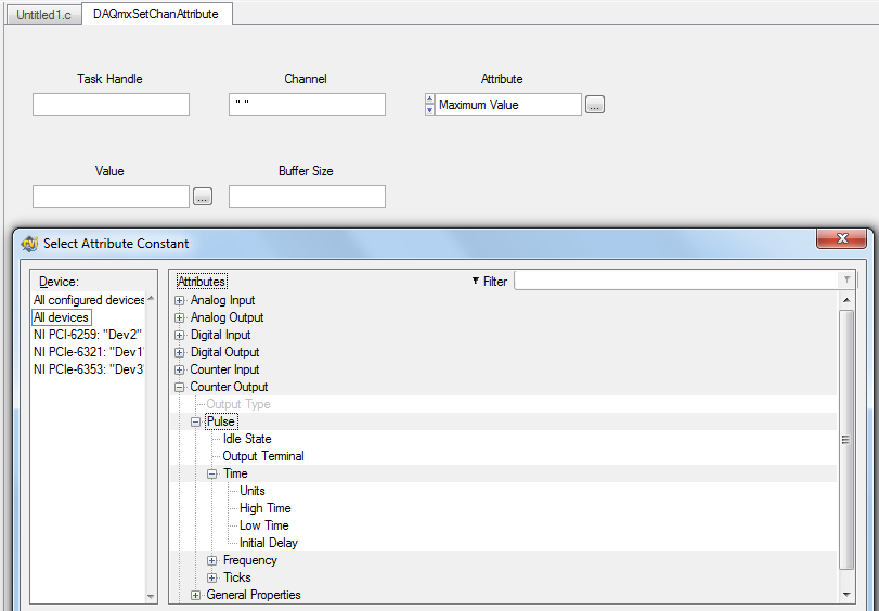
Hello
That should be feasible through the channel attributes. You can read or crush your channel (such as real estate in LabVIEW) attributes. Two of these attributes are high and low times:
DAQmxSetChanAttribute (gTaskHandle, "", DAQmx_CO_Pulse_HighTime, 0.1);  //high time = 100ms
DAQmxSetChanAttribute (gTaskHandle, "", DAQmx_CO_Pulse_LowTime, 0.2);   //low time = 200ms
In addition, I join a screenshot of the Service Commission:
Was what you were trying to get?
Best regards
-
I'm trying to identify the frequency of the sine wave signal and convert it in full. Is it easier to measure in the time domain or frequency domain? According to what is easier, should what modules and functions I use? Another engineer and I was able to go around and around to try different approaches, but just cannot find a working solution. Any help you can give is appreciated.
Bill
Bill,
I see two ways:
For higher frequency sine waves - use module of the FFT. Then the module of statistical values in mode 'Position Max' retrieves the frequency of the amplitude higher in the range.
For low-frequency sine waves, especially those where the full waveform is not in a single block, so you want to try the Pulse analysis Module. To do this, you must change the sine wave to a pulse, using the trigger module. This assumes a pure sinusoidal signal and it becomes a trigger pulse when the value rises above 0. In the simulation, this works well. I don't know how it will work with real data.
I have attached an example illustrating the techniques and results for each frequency of waveform using FFT and analysis Pulse.
-
Digital output frequency seems to be twice the frequency generated by the basic function generator
Hi Labview forum,
I wrote a program (attached) Labview to generate 3 PWM, square wave, signals that has the same frequency and phase delay right (so that when a signal is off, the other signal is lit. Then the next signal). Everything seems to work fine except that the frequency of the PWM signals generated seems twice as the frequency given to the basic function generator. Anyone have any idea why this is happening? Anyhelp would be greatly appreciated.
Thank you!
Totally agree with the advice of all GerdW than the hardware timing of your hardware DAQ will be much more reliable. That said, part of what you are probably hitting is a little quirk of the primitive delay msec. Requests for 1 msec have long been particularly little reliable (although they * seem * to have improved in recent years, probably due to the better OS support in Win 7 or something).
I did minimal mods to your code with comments from you switch to a timed loop. My quick test showed he is good enough to hit the 1 length of loop of target msec.
-Kevin P
-
Calculation of the frequency of real output of a PXI-5402
I have a card PXI-5402, sitting in a high chassis. I'm only interested in the sine wave output at frequencies up to about 10 kHz. I know that it is possible to request an output frequency and then interrogate the acutal output frequency but I prefer to be able to calculate before hand. All I can find in the literature is a figure of 0.355uHz for the frequency resolution.
Is there a better description of the frequency resolution? If this is not the case, the resolution is exactly 0.355uHz or is it an approximation (to 3 significant digits)?
This webcast is a great way to learn the process including the NI 5402 5406 OR exploit to generate periodic duty: http://www.ni.com/webcast/75/en/
The 0.355uHz value is a theoretical value of the frequency rate achievable depending on the size of the accumulator Phase and clock frequency. It's the closest thing I can find on ni.com that you can use to calculate the value: http://zone.ni.com/reference/en-XX/help/370524R-01/siggenhelp/ni_5401_11_31_frequency_resolution_and...
According to me, Fc for the NI 5402/5406 must be 100M and the size of the accumulator is 48 bits. Frequency resolution so = Fc / 2N = (100 × 10 ^ 6) / 2 ^ 48 = 3.55271368e - 7
Keep in mind that the device has a VCXO frequency accuracy specification of + / 25ppm, if you have no PLL block him to a better source.
-
PXI-6133 Pulse frequency output and input with DAQmx
I am trying to set a pulse meter output frequency task and read this signal with a frequency counter input task input pulses. I use a 2 PXI-6133, each connected to a BNC-2090 case has. I want to output a square of a certain frequency with the task frequency meter pulse output and then read the frequency of this signal using a task of cost input frequency. I don't know how to property set up these tasks, or how to define which device to use for each heap. I don't know what terminals on the BNC-2090 is the counter of entry/sortient channels correspond to them because that is not displayed in the documentation of the PXI-6133 or documentation of BNC-2090.
Please see the attached VI for my attempt to put this in place. Currently, I get two errors:
(1) error-200452 took place at the property Node DAQmx channel meter Test - referred to as property is not supported by the device or is not applicable to the task.
2. the error-89136 at DAQmx Start Task - specified route cannot be met because the hardware does not support.
If I remove two channels of property DAQmx where I try to put the terminals for the counters, while the program is running, but then I know not what terminals on the BNC-2090 meters are connected to! This causes the DAQmx read for the cost in the tasks of frequency to timeout because it does not detect a signal.
I would really appreciate the help to properly configure these tasks and determine what terminals on the BNC-2090 case has the task of counter will work on.
I see a few problems in the code originally:
- For your CI task, you type is defined as a counter entry > frequency. But on the node property of DAQmx channel for this task, you modify the CI. Property of PulseWidth.Term. It should be CI. Freq.Term. set the entry regardless of the PFI line you do not want the input signal on. Tip: you don't have to type the name of the device in at all. Enter "PFI0", it's the same as "DevN/PFI0" since the unit has already been specified in the DAQmx Virtual Channel Create function. The name of the device, leaving aside will make your code more flexible where you decide later to change the name of the device.
- Maps of the S series, such as the 6133, do not have the same flexibility to change the output terminals of tasks of meter you might find with M or X series device. Page 83 of the S series manual watch what signals can be extracted to PFI lines - Ctr0Out is not one of these. Instead, Ctr0 out is, by default, pin 2. Cabling to a BNC-2090 6133 is certainly difficult to understand out (probably because the 2090 was designed to work with the materials of the E and M series), but if you compare the pinout of a PXI-6255 0 with the 6133 pinout connector, you will notice that they are essentially a match 1-1. Pin 2 is PFI12 on the 6255, so I assume the same for the 6133. All this to say, Ctr0Out always appears on the pin 2/PFI12 for the 6133 and you therefore cannot change the output terminal that your code is trying to do, having for result error-89136. Remove this node from the property altogether and the error should disappear.
-
Output power of the frequency spectrum
Hello
I have a pretty simple question. I m using the power spectrum of FFT and PSD vi. and have trouble understand output frequencies. If I understand the first line is DC-value and delta frequency then describe the following frequencies. But when I put for example in 8 points say sampling frequency of 4 Hz = 2 seconds of data to analyze, I'll be back 4 lines of data (including 0). If the first is DC, then the 2nd should be 1 / 2 Hz 1 Hz = 3rd place and 4th place = 3 / 2 Hz, but what about the frequency of 2 Hz Nyquist, why Don t I get this one? or is there something I don't understand?
I also tried the example of Units.vi of FFT spectrum and can understand, but I still Don t get it.
Help, please!
Best
Jesper
FFT returns to power in frequency bins. The frequency of the bins is determined by the Fs (sampling frequency) divided by N (number of points), from DC (0Hz). For your case, the table returned would be:
Bin 0: 0-0.5 Hz
Bin 1: 0, 5 - 1 Hz
Tray 2: 1-1.5 Hz
Bin 3: 1.5 - 2 Hz
So effectively Bin 3 holds the power of 1.5 to 2 Hz (which contains your Nyquist frequency).
-
Frequency of maximum output with USB-6008
I have a digital circuit containing 3 exits, 3 inputs digital and analog 1 entry in labview with my USB-6008. When I connect to the entrance (via the DAQ assistant) analog, the output frequency is reduced to a maximum of 27 Hz, but I need 50 Hz. is possible to do?
Ah. You'll need a DAQ better than the 6008, to do.
There is no train generation feature buffering or the pulse on the 6008. The outputs are all timed by the software, you cannot build a table and tell the 6008 in the output array. Out of the 6211 must be able to produce this signal. Series X-series Renault will do what it takes; the USB-6341 is probably your best option.
-
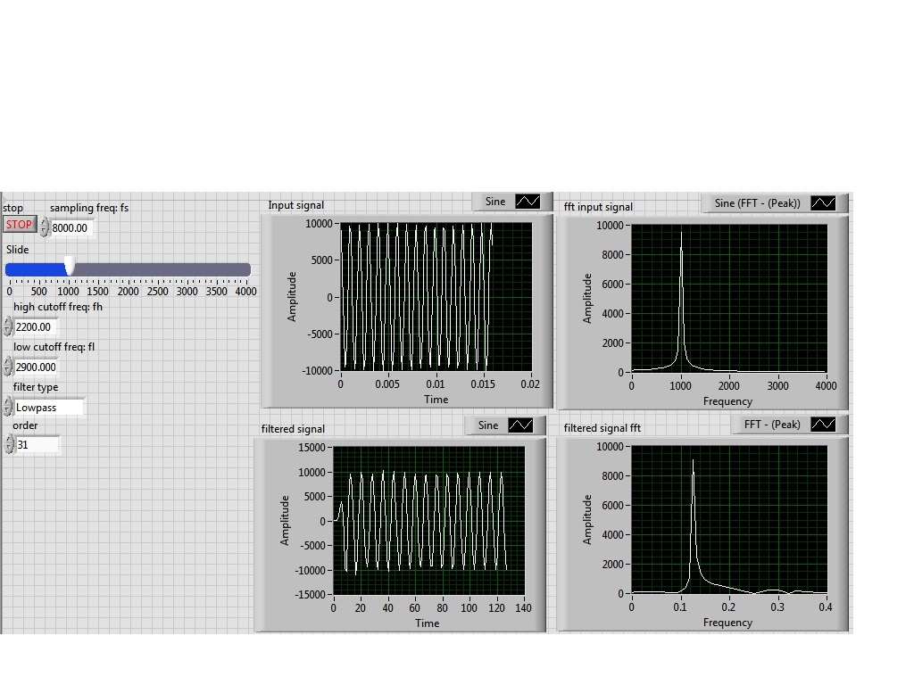
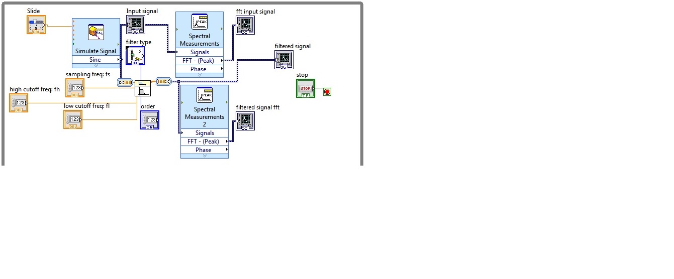
I'm simulating a sine wave at approximately 1000 Hz (I'm variable according to the frequency with a slider), I would like to pass this signal by a lowpass filter (butterworth) with a high frequency of 2200 Hz cuttoff and a low pass to 2900 Hz frequency. However, the output after the filter frequency seems to be lower in the order of a thousand. the output frequency is about 0.1 Hz.
Y at - it someone who can guide me please to solve this problem, I tried different filters and I'm still having this problem, it would be incorrect sampling?
I enclose the block diagram and the front panel
Because you use express screws and the type of dynamic data...
You convert the signal of DDT (which contains the clock information) in a table DBL to perform filtering. Take it a DBL array (which contains no data of timing) and converted it into a DDT (which now contains no data timing). That's why when you try to view and analyze it you have lost all the data timing (frequency).
If you were to exit table DBL of your filter and build a wave form and provide the dt to the waveform of the sampling frequency control, then it will work.
Better yet, ditch the DDT and use waveforms from the beginning
-
Frequency control of NOR-9476 on the cDAQ-9188
I am using a cDAQ-9188 with a NI 9476 module, and I would like to control the frequency of the digital signals that the module was released. I tried to use the example of Pulse Train digital continuous with control of the frequency, but impossible to select the 9476 since there is no internal counter, and when I change the 'Digital output' task, the frequency control disappears. Is it possible to use the internal counter of frame to control the output frequency of the 9476? I need to get out a range of 0 to 1 kHz.
Most of my program would output a digital signal of a certain frequency every second in real time from a given table. For example, if I have an array of [10, 20, 15, 100,...], it generates a model of up/down of 10 cycles per second for a second, followed by 20 cycles (with a shorter period) for a second, then 15 cycles per second for a second, and 100 cycles per second for a second.
I tried to use avoiding to do, but it was very slow, with a delay of 63 ms between each cycle, when I wanted a 1 ms delay.
CDAQ-9188 has 4 counters built in, but you cannot access it by using the NI 9476-, but the NI 9401 module can access the built-in meters.
The good news is that you can always generate your pulse train, using counters, it generate on the PFI lines on the chassis itself and not through your module. If you need to generate more than a pulse train, or use all four counters, you will need the module NOR-9401/9402.
In order to get the speed, you will need to use the capabilities of hardware counters timing.
I hope this helps!
For more information:
-
The amplitude of the frequency. Bode CD. State space
Hi all
Gently, I have a simple model that gives me a Bode phase and magnitude, using the block 'CD Bode'. AFAIK, this block takes the representation of the State space and assesses the frequency and scale of the system.
Can I change the value of the Phase or amplitude Bode? by means change the input signal that bode uses to evaluate the response of the State space?
Note: The entry, I want to say here is the value of the sinusoidal signal that Bode uses to give the phase and the amplitude of the State space.
Thank you
The works of Bode CD functions as a "sweep" of all frequencies and who you are. The algorithm is not a frequency controlled, he comes back the entire spectrum. You can't just get a specific frequency. However, if you use the fuction 'Assess frequency of CD', you can provide the model and frequency, and this will give you the specific Mag/Phase for this frequency. This example shows how to do this in LabVIEW:
C:\Program Files (x 86) \National Instruments\LabVIEW 2014\examples\Control and Simulation\Control Design\Time Analysis\CDEx Lin Simulation and stable State.vi
Now, if you want to 'form' your frequency, so you can create another model, connect with each other and try to change the output frequency. This example shows how to do this:
C:\Program Files (x 86) \National Instruments\LabVIEW 2014\examples\Control and Simulation\Control Design\Frequency Analysis\CDEx frequency analysis
If you just want to "simulate" the response of the signal to a specific sine wave, then you will need to you another function in the time domain palette called "linear Simulation CD. With this, you can generate a specific sine wave and you can see his behavior in the time domain. Here is an example:
C:\Program Files (x 86) \National Instruments\LabVIEW 2014\examples\Control and Simulation\Control Design\Time Analysis\CDEx sine wave with Mathscript.vi
Hope this helps,
-
Analog outputs with different time scales
I use products AO of a card PCI-6731 for an application scan head and I have some difficulties to achieve peak performance, that I need. I am contolling the map with nidaqmx drivers in c ++
Basically, an output controls scanning in the direction Y (which is a line of scanning and is very fast) and the other in the X (increment once per scan line, so much slower). The complication is that both exits start at an external trigger, because positioning is synchronized to a separate data acquisition card.
Now, what I do is:
-write the scanline for 0 output waveform
-set output 1 to a given position
-say next Trigger output card
-hangs at the end and stop tasks
What I really want to do, it is just tell him to start with on each external trigger output waveform of scanline 0 and output 1 increment to the next position. So I could do a complete 2D scanner with a minimum of control software.
Any ideas on how I could best achieve this? My understanding of the nidaqmx drivers I don't see an elegant way to do it.
I could potentially do some operations on the done callback, although it makes me a little nervous because the control PC running windows, it is not a real-time operating system.
Hmm I do not know exactly but there are a couple of things (it is close)...
The output frequency of meter in your example 5 MHz (20 MHz, 2 high ticks, weak 2 ticks), which is faster than holders 6731 for a sample clock. I thought that this would have given a material error... are you looking for errors once the task runs (for example using DAQmxIsTaskDone)?. There is a DAQmxCreateCOPulseChanFreq if you want to set the clock frequency directly (it will use the appropriate default internal time base).
The task of counter generates 1000 pulses per trigger, is what determines the number of samples generated by the trigger (I assume that you want it to be 1024 aka "numSamples").
The analog output task must either use:
(1) calendar continuous if the output will repeat indefinitely as several triggers are acquired.
(2) finishes pitch (N * numSamples) samples where N is the number of lines that you want to exit and numSamples is the number of samples per line. In this case, the task will end once the lines were triggered.
Best regards
-
Output broken for writing DAQmx
Hello
I need emergency assistance with a problem I have with write DAQmx. The 'DAQmx write VI' is located inside a while loop that repeats every 20ms. I use queues to transfer data between several asynchronous VI and the data does not update all 20ms. Because I'm not going to tie the whole project I faked the timing of 20ms to 'Wait for next ms Multiple' vocation. What happens is I will send 20ms of data to the VI DAQmx writing, he will have all the data output with 4ms can sit idle for 16ms. I implemented the task for the DAQmx example 1000 per channel at a rate of 50 kHz, which should take all 20ms to the exit. I also checked the waveforms of entry the entry have 1 k samples and a detachment of the 2nd-5. When I went from the DBL 2D table has not changed. I want to emphasize that all data is sent into the 4 DC. It's confermed visulaly and with the node 'written examples.
I did a test where I hosted my VI to run as fast as possible. In this case, the output was a sine curve, but looking more closely, I found that the output frequency of 25 Hz 5 times faster than the signal that I sent to the writing DAQmx VI. In addition if you limit the loop to 10ms iterate the data is output for 4ms and the idle 6ms.
I know that everything is configured correctly. I rechecked the data I sent you the properties of the task. She should be out correctly, but it isn't. I tried calling support NEITHER and he was not particularly helpful.
The equipment I use is a PXI 6723 AO map. I will attach a vi that anyone could run and I will attach a picture of the exit on an oscilloscope. Thnak you for the help
-James
I solved my problem. I needed to add a calendar DAQmx and DAQmx writing change the task before entering the while loop. I use the calendar to set the mode of the sample and the source of the command, while simple DAQmx writing sends and matrix of zeros. With these added it works very well.
-James

Maybe you are looking for
-
Micro does not work after 9.3.2
Update micro 6 more for 9.3.2,and stopped working for imessage/dictation and Siri. The voice still work memo. I tried several resets holding home and power buttons, turned Siri market, on the removal of noise and goes out. Is this a bug with the n
-
I have a user on a current Mac Pro Yosemite running. She has downloaded Office 2016 recently now that our company has passed to Office 365. All office programs are evidence of strange has in a placeholders squre in the menus, tabs, login screens, etc
-
Pavilion G7: Network driver needed
Hi, I have HP PAVILION G7 os is windows 7 (64-bit) I can't find the driver for ethernet and network controller This message is in network controller propertertis that the drivers for this device are not installed. PCI\VEN_1814 & DEV_5390 & SUBSYS_163
-
Not able to access Xbox live 360
Xbox 360 live how much more alive would fall for Xbox 360 live