Wide output frequency input
I'm trying to identify the frequency of the sine wave signal and convert it in full. Is it easier to measure in the time domain or frequency domain? According to what is easier, should what modules and functions I use? Another engineer and I was able to go around and around to try different approaches, but just cannot find a working solution. Any help you can give is appreciated.
Bill
Bill,
I see two ways:
For higher frequency sine waves - use module of the FFT. Then the module of statistical values in mode 'Position Max' retrieves the frequency of the amplitude higher in the range.
For low-frequency sine waves, especially those where the full waveform is not in a single block, so you want to try the Pulse analysis Module. To do this, you must change the sine wave to a pulse, using the trigger module. This assumes a pure sinusoidal signal and it becomes a trigger pulse when the value rises above 0. In the simulation, this works well. I don't know how it will work with real data.
I have attached an example illustrating the techniques and results for each frequency of waveform using FFT and analysis Pulse.
Tags: NI Products
Similar Questions
-
PXI-6133 Pulse frequency output and input with DAQmx
I am trying to set a pulse meter output frequency task and read this signal with a frequency counter input task input pulses. I use a 2 PXI-6133, each connected to a BNC-2090 case has. I want to output a square of a certain frequency with the task frequency meter pulse output and then read the frequency of this signal using a task of cost input frequency. I don't know how to property set up these tasks, or how to define which device to use for each heap. I don't know what terminals on the BNC-2090 is the counter of entry/sortient channels correspond to them because that is not displayed in the documentation of the PXI-6133 or documentation of BNC-2090.
Please see the attached VI for my attempt to put this in place. Currently, I get two errors:
(1) error-200452 took place at the property Node DAQmx channel meter Test - referred to as property is not supported by the device or is not applicable to the task.
2. the error-89136 at DAQmx Start Task - specified route cannot be met because the hardware does not support.
If I remove two channels of property DAQmx where I try to put the terminals for the counters, while the program is running, but then I know not what terminals on the BNC-2090 meters are connected to! This causes the DAQmx read for the cost in the tasks of frequency to timeout because it does not detect a signal.
I would really appreciate the help to properly configure these tasks and determine what terminals on the BNC-2090 case has the task of counter will work on.
I see a few problems in the code originally:
- For your CI task, you type is defined as a counter entry > frequency. But on the node property of DAQmx channel for this task, you modify the CI. Property of PulseWidth.Term. It should be CI. Freq.Term. set the entry regardless of the PFI line you do not want the input signal on. Tip: you don't have to type the name of the device in at all. Enter "PFI0", it's the same as "DevN/PFI0" since the unit has already been specified in the DAQmx Virtual Channel Create function. The name of the device, leaving aside will make your code more flexible where you decide later to change the name of the device.
- Maps of the S series, such as the 6133, do not have the same flexibility to change the output terminals of tasks of meter you might find with M or X series device. Page 83 of the S series manual watch what signals can be extracted to PFI lines - Ctr0Out is not one of these. Instead, Ctr0 out is, by default, pin 2. Cabling to a BNC-2090 6133 is certainly difficult to understand out (probably because the 2090 was designed to work with the materials of the E and M series), but if you compare the pinout of a PXI-6255 0 with the 6133 pinout connector, you will notice that they are essentially a match 1-1. Pin 2 is PFI12 on the 6255, so I assume the same for the 6133. All this to say, Ctr0Out always appears on the pin 2/PFI12 for the 6133 and you therefore cannot change the output terminal that your code is trying to do, having for result error-89136. Remove this node from the property altogether and the error should disappear.
-
6211 DAQ high output frequency
HI guys.
Ive had my hands on hardware DAQ USB 6211. Im trying to generate a signal of high output frequency of one of the 2 counters. The frequency is of the order of 5 to 20 kHz. Can someone tell me if this is possible with this device USB 6211?. Ive been searching but cant seem to find the answers. Are the counters on this device just to read the entries of high frequency or can also ouput. Any help would be appreciated.
Thanks for your reply
 . Ive since found code that does exactly what I want. This isn't in the examples of labview so can someone find it useful. See the attached VI.
 -
I created scripts as follows
CREATE TABLE STUDENTS(
  STD_ID Number,
  STD_NAME Varchar2(25 ) CONSTRAINT SYS_C002716 NOT NULL,
  PHONE_NUMBER Char(20 ),
  FATHER_ADDRESS Varchar2(100 ),
  BASIC_GRADE Number(38,0),
  REGISTER_DATE Date,
  COMMENT_ON Char(200 ),
  STD_ADDRESS Varchar2(100 ),
  STD_RESPONSIBLE Varchar2(100 ),
  RESPONSIBLE_RELATION Varchar2(50 ),
  MOTHER_NAME Varchar2(30 ),
  STUDENT_TYPE Varchar2(10 ),
  YEAR Char(50 ),
  STD_NUMBER Number
)
/

-- Add keys for table STUDENTS

ALTER TABLE STUDENTS ADD CONSTRAINT SYS_C002717 PRIMARY KEY (STD_ID)
/

-- Table CLASSES

CREATE TABLE CLASSES(
  CLASS_NAME Char(40 ),
  CLSS_NUM Number(38,0) CONSTRAINT SYS_C009724 NOT NULL,
  LEV_ID Number(38,0)
)
/

-- Add keys for table CLASSES

ALTER TABLE CLASSES ADD CONSTRAINT KEY3 PRIMARY KEY (CLSS_NUM)
/
-- Table STUDENT_AND_CLASSES

CREATE TABLE STUDENT_AND_CLASSES(
  STD_ID Number NOT NULL,
  CLSS_NUM Number(38,0) NOT NULL
)
/

-- Add keys for table STUDENT_AND_CLASSES

ALTER TABLE STUDENT_AND_CLASSES ADD CONSTRAINT Key4 PRIMARY KEY (STD_ID,CLSS_NUM)
/
I wrote a query: -.insert into students(std_id,std_name) values (1,'abk'); insert into students(std_id,std_name) values (63,'saad'); insert into classes(class_num,class_name) values (3,'abk'); insert into classes(class_num,class_name) values (2,'osm'); insert into classes(class_num,class_name) values (1,'amr'); insert into student_and_classes values(1,1) insert into student_and_classes values(2,63)SELECT STD_NAME ,CLASS_NAME FROM STUDENTS S , CLASSES C WHERE STD_ID IN (SELECT STD_ID FROM STUDENT_AND_CLASSES) AND CLSS_NUM IN (SELECT CLSS_NUM FROM STUDENT_AND_CLASSES)
I expect that the query gives me student_nameSTD_NAME CLASS_NAME ------------------------- ---------- abk amr saad amr abk OSM saad OSM
in the class name and a not to expect to get the output frequencyHello
Thanks for posting the CREATE TABLE and INSERT. Be sure to only test instructions before committing. Do you really want to use class_num in some places and clss_num (without the letter ' a') in other places?
In addition, you must explicitly name the columns in INSERT statements. For example:INSERT INTO student_and_classes (class_num, std_id) VALUES (2, 63);Don't forget to post the exact results you want from the sample data you give and explain how you get these results from these data.
The query you posted checks corresponding to the std_id of the students table a few std_id in the student_and_classes table, and the class_num of classes corresponds to some class_num from the categories table, but these student_id and the don'thave to class_num to be on the same line. I susepct you want something like this:
SELECT s.std_name , c.class_name FROM students s JOIN student_and_classes sc ON sc.std_id = s.std_id JOIN classes c ON sc.class_num = c.class_num ; -
How to upgrade output during input/output synchronized?
Hello
We use an input/output series card m PCI-6289 to provide participants sound while recording the EEG.
Our inputs and outputs are synchronized using the diagram that is attached.
To date our output audio segments have been relatively short. However, now we want to output sounds which last a long time. I've run into shortages of memory by using the current diagram.
Could someone suggest how I could update the audio output, regularly with pieces short 1 sec, in the loop in the diagram attached?
I tried to move the DAQmx Write.vi (point 4 on the diagram) inside the loop, but the output signal was not correct.
Thank you very much for your advice!
Frenk
Hi Frenk,
Can you be more specific about the error that you are experiencing?
Have you heard of the regeneration of analog output? It can be used with a property DAQmx writing node.
Regeneration is the repetition of the data already in the buffer. Standard regeneration is when the PC buffer data are continually downloaded on the FIFO to write. If the data buffer is smaller than the size of the FIFO, it is copied as many times as possible in the FIFO before the start of the generation. This is done to reduce the risk of errors of bandwidth by transferring is not the new data down to the FIFO fairly quickly. Once started, the generation of the copies of the data are no longer manufactured to fill the buffer. New data can be written in the buffer of PC at any time without interrupting the output.
You can also use the FIFO regeneration. With regeneration of the FIFO, the entire buffer is downloaded on the FIFO and regenerated from there. Once the data is uploaded, new data cannot be written to the FIFO. To use the FIFO regeneration, the whole buffer must fit within the size of the FIFO. The advantage of using the FIFO regeneration is that it requires no communication with memory primary host after the operation started, thus avoiding any problems that arise due to the excessive movement of buses.
Take a look at this link which travels with the regeneration: http://www.ni.com/product-documentation/3874/en/
-
PXI-6120 digital output frequency
Hello
before that I have to post my question some technical information:
LabVIEW: 2011.
IO digital 8 PXI-6120.
I read the user manual and search the Forum and there is no reference to the frequency of digital output (only for a meter).
My question is what is the maximum frequency that I can generate outputs digital?
The best I could do is 50 kHz using the example.
Thank you
Sokal
-
output and input simultaneously
Hello
I create a LabVIEW application in 2012 using a DAQ USB-6341 in the series X and DAQmx 9.5.5. I'm a bit ambiguous on the issue of handling the task. Here's what I want to do:
The LabVIEW program will automate a study that will include a series of tests.
Each trial starts with the push of a button.
Once the trial begins, I want to taste three analog inputs on the acquisition of data continuously.
A specified number of seconds after the start of the trial, I want to send a signal to one of the analog output DAQ channels that will communicate with a pacemaker.
Then the trial will end by pressing another button and the tasks will be closed.
That's what I'm not clear on: I understand that only an Analog input or output task can communicate with an acquisition of data at a time, when I try to perform a task that is greater than 1, I get error 50103. However, it is alo I understand that all the pathways involved in a task must be of the same type IO.
So my question is: is it possible for me to taste constantly during my tests and also a signal of output during the trial and if so, how do I configure tasks? I have attached a VI with what I have created so far. It runs only the attached party. If someone could help me understand the output, I would be very grateful.
Thank you
Quinn
Hey Quinn,
You can set a task to separate with its own clock source analog output. On the X series devices, tasks of analog input and analog output have their own internal timing engines on which you can use.
-
To a port mentioned in MAX output frequency
Hello
I'm trying to AC output. 100 kHz on a port PIF using NI 6351. I used the example of Bank OR example and it works fine with the following code.
       DAQmxErrChk (DAQmxCreateTask("",&gTaskHandle));
        DAQmxErrChk (DAQmxCreateCOPulseChanFreq(gTaskHandle, aChannel, aVirtualAddress, DAQmx_Val_Hz, aIdle, 0.0, aFreq, aDuty));
        DAQmxErrChk (DAQmxCfgImplicitTiming(gTaskHandle, DAQmx_Val_ContSamps, 1000));
In the above example, I am creating a COPulseChannel and consolidate represents its physical address (for example Dev1/ctr2) and aVirtualAddress is that I can attribute to this physical address for later use.
My question is:
How can I create a virtual channel in MAX and use its name here with a name to say "myFrequencyChannel" and then write a function for the output channel frequency?
Motivation:
This has been possible until now for all channels as I/AO/DI/DO, where I set all channels with virtual names in MAX and then everything just accomplished tasks by sending their names (only) to my duties. Therefore the user must remember always physical channel but just virtual channel names.
Thanks in advance.
Concerning
RB
Hello
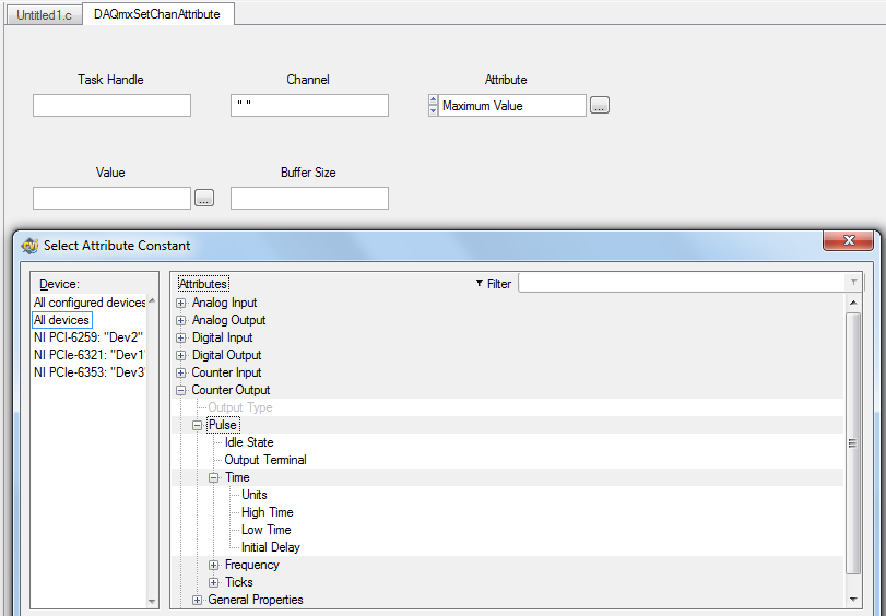
That should be feasible through the channel attributes. You can read or crush your channel (such as real estate in LabVIEW) attributes. Two of these attributes are high and low times:
DAQmxSetChanAttribute (gTaskHandle, "", DAQmx_CO_Pulse_HighTime, 0.1);  //high time = 100ms
DAQmxSetChanAttribute (gTaskHandle, "", DAQmx_CO_Pulse_LowTime, 0.2);   //low time = 200ms
In addition, I join a screenshot of the Service Commission:
Was what you were trying to get?
Best regards
-
In c#, how set digital Ports lines outputs or inputs
Can a port contains the input and output lines at the same time?
Hello
The 6221 is a map of the M series for you can configure each individual line as an input or output so you might have a release for your control, then as an input signal as you suggest.
Kind regards
-
cRIO - H bridge using the PWM output and input only encoder control
Hello
I am currently working on a project to control a 230V brushed servo motor using cRIO. The engine drives a linear step and the final project needs to create a control of position of the engine that the user is able to enter a speed, position and control steps to move to this position.
I use a bridge using NOR-9401 and H to power the motor circuit and a PWM output to move the engine. I also have an encoder, quadrature, connected to a NOR-9403 read position and speed. I use the example program of encoder for the NI 9505 - in my application.
There is no voltage or current on the drive circuit sensors so I wouldn't be able to have a closed loop current in this case. The scene release mechanism is such that the position is locked if the motor does not move and I do not need a torque control to keep the engine in place.
To achieve this, I just wouldn't be able to use a single PID VI (probably the FPGA VI express for discrete PID)?
I am not very well versed in the theory of control, and therefore no indication in the common sense would help me a lot.
Thank you very much!
Sexy,.
in general, it is best to use a cascade control loop structure but in principle must also be able to use the output of the control loop of position as an input to the PWM generator. The main disadvantage of this configuration is the current limitation missing. Without current meaning is no longer the only way to protect your engine from drawing too much current to limit to the current maximum output of your diet, or to limit the maximum duty cycle of PWM. Without current information, the last method is quite inaccurate, but better than nothing.
I agree with Mike, you should look in the examples of the 9505 module and use the controller position vi of these examples. This PID controller is optimized for motion control applications and it is implemented in the fixed point arithmetic, offering the best performance on and FPGA.
Kind regards
Jochen Klier
National Instruments
-
possibility to get a DVI - d output monitor input VGA adapter?
My p71126s just bought a 2 monitor DVI - D outputs. I need to enter a flat TV with a VGA input.
Hello
You can by a converter. Converters of higher prices do a better job with VGA, scaling than the cheaper models.
Another option is to buy a discrete video card that has the video ports that you need. That would be my recommendation.
-
HDMI OUTPUT or INPUT on PAVILION G7
I can use it as an output or video input
I want a simple answer, yes or no.
Hello
Only for OUTPUT
Kind regards.
-
How to use the Bpel output as input to the stored procedure
I am a beginner SOA. The scenario is to use the output of a BPEL process in a procedure stored as input and validate it against the data in the database. The data received from the BPEL are compared with fields from different tables.
It's basically a business process data validation.
The output of BPEL is an Xml file and how it can b used in the query of a procedure?
Published by: 869091 on June 29, 2011 12:14 AMThe output of the BPEL process is in XML format.
Your requirement is not clear, please state it correctly what you doing.Yatan-
-
Digital output frequency seems to be twice the frequency generated by the basic function generator
Hi Labview forum,
I wrote a program (attached) Labview to generate 3 PWM, square wave, signals that has the same frequency and phase delay right (so that when a signal is off, the other signal is lit. Then the next signal). Everything seems to work fine except that the frequency of the PWM signals generated seems twice as the frequency given to the basic function generator. Anyone have any idea why this is happening? Anyhelp would be greatly appreciated.
Thank you!
Totally agree with the advice of all GerdW than the hardware timing of your hardware DAQ will be much more reliable. That said, part of what you are probably hitting is a little quirk of the primitive delay msec. Requests for 1 msec have long been particularly little reliable (although they * seem * to have improved in recent years, probably due to the better OS support in Win 7 or something).
I did minimal mods to your code with comments from you switch to a timed loop. My quick test showed he is good enough to hit the 1 length of loop of target msec.
-Kevin P
-
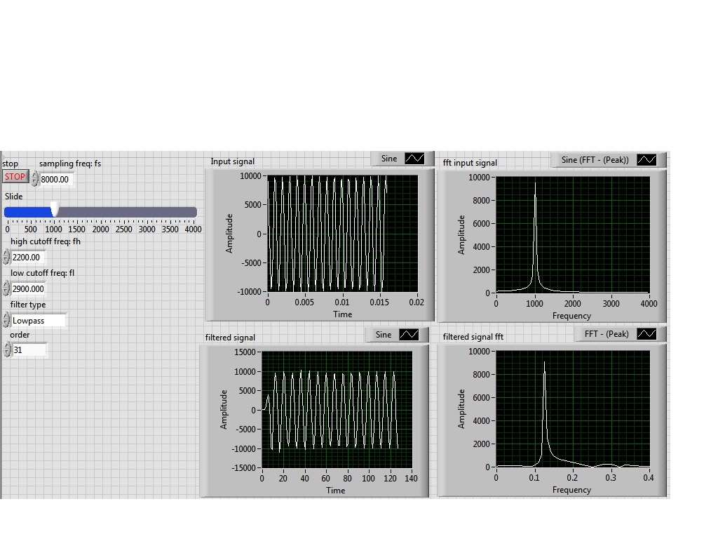
I'm simulating a sine wave at approximately 1000 Hz (I'm variable according to the frequency with a slider), I would like to pass this signal by a lowpass filter (butterworth) with a high frequency of 2200 Hz cuttoff and a low pass to 2900 Hz frequency. However, the output after the filter frequency seems to be lower in the order of a thousand. the output frequency is about 0.1 Hz.
Y at - it someone who can guide me please to solve this problem, I tried different filters and I'm still having this problem, it would be incorrect sampling?
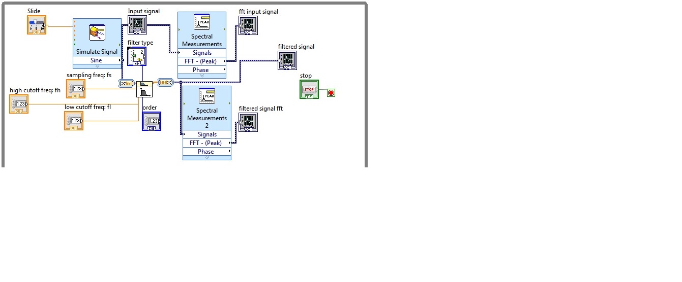
I enclose the block diagram and the front panel
Because you use express screws and the type of dynamic data...
You convert the signal of DDT (which contains the clock information) in a table DBL to perform filtering. Take it a DBL array (which contains no data of timing) and converted it into a DDT (which now contains no data timing). That's why when you try to view and analyze it you have lost all the data timing (frequency).
If you were to exit table DBL of your filter and build a wave form and provide the dt to the waveform of the sampling frequency control, then it will work.
Better yet, ditch the DDT and use waveforms from the beginning

Maybe you are looking for
-
Some programs using windows 10 ask for flash has to be installed, but it is already!
10% of my programs (e.g. Pandora) ask for the Flash needs to be installed, but the last Flash is already installed. These programs run on Chrome. Technical support for these programs say just move to Chrome. Any ideas?
-
NATTERING DISAPPEARED WHEN PAGING BACK OR BY CLICKING ON A NEW SITE BUT STILL THE WORDS IN IE8
NATTERING DISAPPEARED WHEN PAGING BACK OR BY CLICKING ON A NEW SITE BUT STILL THE WORDS IN IE8. I JUST REINSTALLED FIREFOX AND THE NATTERING DISAPPEARED WHEN CHANGING PAGES.
-
Automatically deleted registry key
Recently, we upgraded to dot net framework 4.0.Our site are asked to use the extension less URLS. " That's why we've added the" EnableExtensionlessUrls "Dword with the following path and set its value to '0'." HKEY_LOCAL_MACHINE\SOFTWARE\Microsoft\AS
-
http://Huawei mount
-
Microsoft Teredo Tunneling adapter device"does not work correctly.
Hi Sir/Madam Hello, can you help me find driver problems, sir.i am on hp pavilion g6 Series notebook.i found this message there, Windows reports that the "Microsoft Teredo Tunneling adapter" device is working properly. But I opened the Device Manager