6211 DAQ high output frequency
HI guys.
Ive had my hands on hardware DAQ USB 6211. Im trying to generate a signal of high output frequency of one of the 2 counters. The frequency is of the order of 5 to 20 kHz. Can someone tell me if this is possible with this device USB 6211?. Ive been searching but cant seem to find the answers. Are the counters on this device just to read the entries of high frequency or can also ouput. Any help would be appreciated.
Thanks for your reply  . Ive since found code that does exactly what I want. This isn't in the examples of labview so can someone find it useful. See the attached VI.
Tags: NI Software
Similar Questions
-
vary the value of output of the digital HIGH output voltage.
Hello
Is it possible to vary the values of the NOR-DAQ HIGH output voltage. If Yes please tell me how to do the same. I want to reduce tension before moving out of my camera, digital signal as my rating of device is only 3 volts for the digital HIGH.
Kind regards
Pradeep.
The digital output voltages cannot be changed on your USB-6259 (that you mentioned that you use in a different thread). Please see the specifications for more information on the digital logic levels used on your Board.
Best regards
-
I created scripts as follows
CREATE TABLE STUDENTS(
  STD_ID Number,
  STD_NAME Varchar2(25 ) CONSTRAINT SYS_C002716 NOT NULL,
  PHONE_NUMBER Char(20 ),
  FATHER_ADDRESS Varchar2(100 ),
  BASIC_GRADE Number(38,0),
  REGISTER_DATE Date,
  COMMENT_ON Char(200 ),
  STD_ADDRESS Varchar2(100 ),
  STD_RESPONSIBLE Varchar2(100 ),
  RESPONSIBLE_RELATION Varchar2(50 ),
  MOTHER_NAME Varchar2(30 ),
  STUDENT_TYPE Varchar2(10 ),
  YEAR Char(50 ),
  STD_NUMBER Number
)
/

-- Add keys for table STUDENTS

ALTER TABLE STUDENTS ADD CONSTRAINT SYS_C002717 PRIMARY KEY (STD_ID)
/

-- Table CLASSES

CREATE TABLE CLASSES(
  CLASS_NAME Char(40 ),
  CLSS_NUM Number(38,0) CONSTRAINT SYS_C009724 NOT NULL,
  LEV_ID Number(38,0)
)
/

-- Add keys for table CLASSES

ALTER TABLE CLASSES ADD CONSTRAINT KEY3 PRIMARY KEY (CLSS_NUM)
/
-- Table STUDENT_AND_CLASSES

CREATE TABLE STUDENT_AND_CLASSES(
  STD_ID Number NOT NULL,
  CLSS_NUM Number(38,0) NOT NULL
)
/

-- Add keys for table STUDENT_AND_CLASSES

ALTER TABLE STUDENT_AND_CLASSES ADD CONSTRAINT Key4 PRIMARY KEY (STD_ID,CLSS_NUM)
/
I wrote a query: -.insert into students(std_id,std_name) values (1,'abk'); insert into students(std_id,std_name) values (63,'saad'); insert into classes(class_num,class_name) values (3,'abk'); insert into classes(class_num,class_name) values (2,'osm'); insert into classes(class_num,class_name) values (1,'amr'); insert into student_and_classes values(1,1) insert into student_and_classes values(2,63)SELECT STD_NAME ,CLASS_NAME FROM STUDENTS S , CLASSES C WHERE STD_ID IN (SELECT STD_ID FROM STUDENT_AND_CLASSES) AND CLSS_NUM IN (SELECT CLSS_NUM FROM STUDENT_AND_CLASSES)
I expect that the query gives me student_nameSTD_NAME CLASS_NAME ------------------------- ---------- abk amr saad amr abk OSM saad OSM
in the class name and a not to expect to get the output frequencyHello
Thanks for posting the CREATE TABLE and INSERT. Be sure to only test instructions before committing. Do you really want to use class_num in some places and clss_num (without the letter ' a') in other places?
In addition, you must explicitly name the columns in INSERT statements. For example:INSERT INTO student_and_classes (class_num, std_id) VALUES (2, 63);Don't forget to post the exact results you want from the sample data you give and explain how you get these results from these data.
The query you posted checks corresponding to the std_id of the students table a few std_id in the student_and_classes table, and the class_num of classes corresponds to some class_num from the categories table, but these student_id and the don'thave to class_num to be on the same line. I susepct you want something like this:
SELECT s.std_name , c.class_name FROM students s JOIN student_and_classes sc ON sc.std_id = s.std_id JOIN classes c ON sc.class_num = c.class_num ; -
To a port mentioned in MAX output frequency
Hello
I'm trying to AC output. 100 kHz on a port PIF using NI 6351. I used the example of Bank OR example and it works fine with the following code.
       DAQmxErrChk (DAQmxCreateTask("",&gTaskHandle));
        DAQmxErrChk (DAQmxCreateCOPulseChanFreq(gTaskHandle, aChannel, aVirtualAddress, DAQmx_Val_Hz, aIdle, 0.0, aFreq, aDuty));
        DAQmxErrChk (DAQmxCfgImplicitTiming(gTaskHandle, DAQmx_Val_ContSamps, 1000));
In the above example, I am creating a COPulseChannel and consolidate represents its physical address (for example Dev1/ctr2) and aVirtualAddress is that I can attribute to this physical address for later use.
My question is:
How can I create a virtual channel in MAX and use its name here with a name to say "myFrequencyChannel" and then write a function for the output channel frequency?
Motivation:
This has been possible until now for all channels as I/AO/DI/DO, where I set all channels with virtual names in MAX and then everything just accomplished tasks by sending their names (only) to my duties. Therefore the user must remember always physical channel but just virtual channel names.
Thanks in advance.
Concerning
RB
Hello
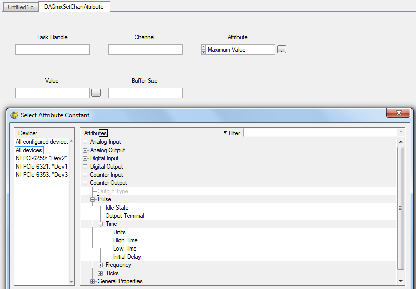
That should be feasible through the channel attributes. You can read or crush your channel (such as real estate in LabVIEW) attributes. Two of these attributes are high and low times:
DAQmxSetChanAttribute (gTaskHandle, "", DAQmx_CO_Pulse_HighTime, 0.1);  //high time = 100ms
DAQmxSetChanAttribute (gTaskHandle, "", DAQmx_CO_Pulse_LowTime, 0.2);   //low time = 200ms
In addition, I join a screenshot of the Service Commission:
Was what you were trying to get?
Best regards
-
I'm trying to identify the frequency of the sine wave signal and convert it in full. Is it easier to measure in the time domain or frequency domain? According to what is easier, should what modules and functions I use? Another engineer and I was able to go around and around to try different approaches, but just cannot find a working solution. Any help you can give is appreciated.
Bill
Bill,
I see two ways:
For higher frequency sine waves - use module of the FFT. Then the module of statistical values in mode 'Position Max' retrieves the frequency of the amplitude higher in the range.
For low-frequency sine waves, especially those where the full waveform is not in a single block, so you want to try the Pulse analysis Module. To do this, you must change the sine wave to a pulse, using the trigger module. This assumes a pure sinusoidal signal and it becomes a trigger pulse when the value rises above 0. In the simulation, this works well. I don't know how it will work with real data.
I have attached an example illustrating the techniques and results for each frequency of waveform using FFT and analysis Pulse.
-
Digital output frequency seems to be twice the frequency generated by the basic function generator
Hi Labview forum,
I wrote a program (attached) Labview to generate 3 PWM, square wave, signals that has the same frequency and phase delay right (so that when a signal is off, the other signal is lit. Then the next signal). Everything seems to work fine except that the frequency of the PWM signals generated seems twice as the frequency given to the basic function generator. Anyone have any idea why this is happening? Anyhelp would be greatly appreciated.
Thank you!
Totally agree with the advice of all GerdW than the hardware timing of your hardware DAQ will be much more reliable. That said, part of what you are probably hitting is a little quirk of the primitive delay msec. Requests for 1 msec have long been particularly little reliable (although they * seem * to have improved in recent years, probably due to the better OS support in Win 7 or something).
I did minimal mods to your code with comments from you switch to a timed loop. My quick test showed he is good enough to hit the 1 length of loop of target msec.
-Kevin P
-
PXI-6120 digital output frequency
Hello
before that I have to post my question some technical information:
LabVIEW: 2011.
IO digital 8 PXI-6120.
I read the user manual and search the Forum and there is no reference to the frequency of digital output (only for a meter).
My question is what is the maximum frequency that I can generate outputs digital?
The best I could do is 50 kHz using the example.
Thank you
Sokal
-
How to save data quickly to the high sampling frequency
Hi all
I use a structure of producers and customers to measure and record the data. The sampling rate must be as high as 10 kHz. Given that so much data, it takes a long time before the data is saved. At first, I saved the data in an excel sheet. Then I tried to save it in binary, but it still takes a while to complete save. How can I make the time savings a short circuit?
Thank you
The best
First we will make some corrections to your DAQmx code. Since you are using continuous sampling, do NOT connect the samples per channel. Which is actually limiting your buffer. And there is really no need to define your buffer size either. It is default to very big, so this isn't a problem as long as you read your data quite often.
Now your data connection... You simply create a very wide range while acquiring data. Then, you save the data. It's actually not through the advantage of using the producer and the consumer. You should save your data in the loop of the consumer. It will be elinate need a lot of memory and you save the data to the file while you are buying.
But, in this case, I say that the producer and the consumer is not even necessary. Use the DAQmx Configure registration VI. With this VI, you can tell DAQmx to disseminate all data directly in a PDM file. You don't have to do anything. It is by far the best way to save on your DAQ data.

-
DAQ digital output default to low Earth
Hello
This probably a basic question, but I have found information on this subject.
When I connect a data acquisition unit (usb6009) to the USB port I get any output defaults to a high (+ 5V) until I run my program and I put them to lower ground.
Is it possible to configure default data acquisition always at 0V?
I enjoy any comments or links on how to change this.
Thank you
Cristian
The default value for the 6009, is that they are all set for entries. What you see is the pull up. But, no, you cannot set the power of the State to the 6009.
-
HAVE high sampling frequency of trigger
Dear community
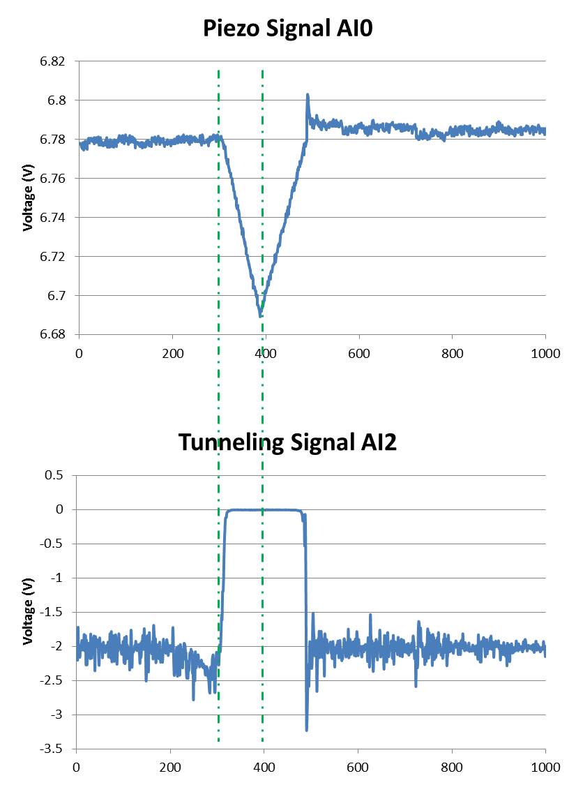
I am using a microscope to tunnel effect from here feeding two voltage signals on my map of acquisition of data USB-6212 (Labview 2013 SP1). A voltage signal is the voltage applied to a piezo in the microscope (AI0). This signal drifting slowly over time and it is noisy. The other voltage signal is a tunnel current is converted into a voltage (AI2) signal (see attached photo):
Ideally, I would like to record the two signals between the lines dotted in a .txt file whenever the event of tip in the top image rises. This should be about every second during a day.
So far, I've written a VI that calculates the moving average of the piezo signal and if the piezo voltage exceeds a certain percentage of the average running it fires a command 'Save as file'. The VI works well for a frequency of 100 Hz, but when I go to 20 kHz, the trigger does not work properly. I am also only watching a lot of a number (in this case, 1000) and if there is a trigger signal in these samples of 1000. So if there's a signal around 0 or 1000 I cut and split into two files that I want to avoid.
I don't have much experience with Labview and probably broke every rule of design in the book.
My question is if there is a smarter way to automatically back up the signal between the same dotted lines at high frequencies of sampling?
I thank very you much in advance!
Hi Mario,.
I rewrote the portions of your VI to improve performance (we hope). No need to three queues. No inquiry unless there is a trigger occurs.
I'm confused by the outbreak that seems to detect the edges of the piezo signal high side, even if the tip is in the negative sense. I modified this logic (eventually) get a threshold top-side of the signal of tunneling.
It is unclear what might happen to 20 kHz. The example shows a constant 1 kHz sampling rate and 1 K samples treated by loop. If the sampling rate is changed to 20 kHz, then the loop will have to run to 20 Hz in order to keep up with the acquired data (@1 K samples per read).
I hope that the joint allows VI (not tested).
-
6008 daq digital outputs to control relays
Hi all, I'm looking to help create a VI to send out digital to a daq 6008 to control relays. What I'm trying to do is when you press start and a condition is met send a digital output to control a relay for 30 seconds or so to take a measured voltage to be taken an analog voltage. After 30 seconds, I want the first relay to switch off and the next relay lights for the same amount of time. I want to continue this sequence to 7 readings, blood for every step and send the data to an excel file. I know it's basic stuff, but my experience with labview is limited! Any help would be greatly appreciated.
Thank you
Paul
Hi Paul,.
I looked on your problem this afternoon and I agree completely Fan Ravens that the state machine is in fact the most appropriate architecture for such a task of data acquisition. A state machine architecture is one of the most commonly used in LabVIEW design patterns and is especially suitable for any program where you have clearly defined the steps that can be represented by the States and rules for the transition between these States.
There is a model of Machine of State Standard contained in LabVIEW which should give you an idea of the underlying architecture and is a good starting point. To give you a better idea of how this architecture can be applied to a data acquisition task, I would recommend that you look at This example. Although States will be slightly different in your case, this should provide you with a good understanding of how you can architect such a request.
I hope this helps.
Best regards
Christian Hartshorne
Technical sales engineer
National Instruments UK
-
How to acquire the signal to very high sampling frequency
Hello world
My name is Luke Ho. I am trying to acquire the signal with Labview (Sthelescope). The signal comes from sensor acoustics, then filters and amplifiers to adapt to ADC rank (0 - 5V). Thus, the maximum frequency of the signal is 40 kHz.
According to the Nyquist theorem, I sampled at least 80 Khz signal.
Is there a sampling frequency devices like that? or y at - it another way of better? I used the Arduino before, but it was about 10 kHz.
I need your advice.
Thank you all and have a nice day.holucbme wrote:
Thanks for your recommendation
But is it possible without USB Data Acquisition, it is quite expensive for me.
This is the cheapest option to NEITHER. I tried to look for options to other companies, but more I found in the same price range, or not answering is not your condition of sample rate.
-
Use of Labview to make a wave custom for the daq for output Wizard
Hey there, I have a table of values that I made in a waveform x.
I was curious to know if this waveform can be printed by my Ni Daq with the Daq assistant, or is there another method to display an array of values via a data acquisition card?
Thank you
You can try to create a new assistant or look at the post at http://forums.ni.com/t5/LabVIEW/Missing-wire-connectors-on-DAQ-Assistant-express-VI-s/td-p/1505788
-
Higher output referenced specifications
What roles are required for graduation card outputs referenced?
Hi Chris,
You will need the role [SPEC_GRADUATOR]. You can find details on the superior functionality Spec in the GSM Guide:
- The upper icon () is available on the specification of materials with an output type of 'External' of a user with the role of [SPEC_GRADUATOR]. By clicking on the icon changes the external output to a material "Referenced" and solves the workflow to a workflow of specifications of the material. The approval of Sourcing section becomes available for an item that has been formed.
-
build the table high sampling frequency
Hello
I have implemented a simple vi which curve data from incoming analog channels, and when you are prompted to save the data, it generates an arrary. When recording is complete, the data is written to a file. I use a local variable between while loops to add data to table. Everything works smoothly. However, when I increase my sampling rate in a few thousand s/s (> 5000 s/s) my final table is not as large as expected. Suggestions to optimize this? I do not undestand where is the neck of the bottle. In the end, I intend to be sampling 8 channels at least 8 000 s/s. The vi is attached in case someone wants to kick something. LabVIEW is fairly new to me.
Thank you
Trevor
Search for "producer/consumer" and how a queue can be used to transfer data between the loops.
What is happening is the loop of your is slows and not juggling with incoming data. The local is being written too.
Put a flag on the terminals of your index fo the two loops to see that a single loop is ahead of the other.
Ben
And if you do not belive me just wait a few minutes and crossrulz will tell you the same thing.
Maybe you are looking for
-
Find a simple computer for a basic task.
I used a Macbook pro for 2.5 years. My husband used a Lenovo think pad for a years doz. It is the processor, read technical reports, including spreadsheets and reads and writes e-mails. Hard drive of the Lenovo is almost dead if a replacement is nece
-
MY Mac Pro 2009 crashes when you use Safari. I can tell when it is about to happen. The screen will start to Flash and the mouse still moves, but you cannot select anything. Sometimes I can get it to unlock by pressing the ESC key.
-
Change the font size in WLM "Inbox" and "folders".
I have a partial vision just downloaded Windows Live Mail and have been unable to expand the size of the font of the messages in the folders and "inbox". Is there a way to change the font size without the system dpi settings?
-
Impossible to download and install the Vista SP2
original title: I was running vista sp2 due to virus I had to do a system recovery, it brought me back to sp1 now I can't download sp2 noor machine windows 7 check I can't download sp2, auditor of windows system 7, etc. Have downloaded a lot of patch
-
Photosmart 7510 - calendar begins with Sunday
Hello I have a 7510 all-in-1. The calendar application that allows you to print a calendar sstarts monthly Sunday as the first day. How can we change this? Thank you